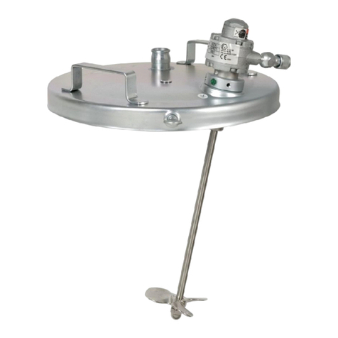
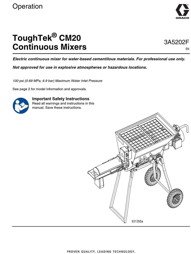
Graco ToughTek CM20 Instruction Manual

3A5202A
EN
Operation
ToughTek
®
CM20
Continuous Mixers
Electric continuous mixer for water-based cementitous materials. For professional use only.
Not approved for use in explosive atmospheres or hazardous locations.
Models 25M530
70 psi (0.48 MPa, 4.8 bar) Maximum Working Pressure
Important Safety Instructions
Read all warnings and instructions in this
manual. Save these instructions.
WLD

23A5202A
Contents
Warnings . . . . . . . . . . . . . . . . . . . . . . . . . . . . . . . . . 3
Component Identification . . . . . . . . . . . . . . . . . . . . 5
CM20 . . . . . . . . . . . . . . . . . . . . . . . . . . . . . . . . . 5
Mix-head Assembly . . . . . . . . . . . . . . . . . . . . . . . 6
Water Control Assembly . . . . . . . . . . . . . . . . . . . 6
Setup . . . . . . . . . . . . . . . . . . . . . . . . . . . . . . . . . . . . . 7
Prepare Unit for Operation . . . . . . . . . . . . . . . . . 7
Water Connections . . . . . . . . . . . . . . . . . . . . . . . 8
Electrical Components . . . . . . . . . . . . . . . . . . . . 8
Grounding . . . . . . . . . . . . . . . . . . . . . . . . . . . . . . 8
Operation . . . . . . . . . . . . . . . . . . . . . . . . . . . . . . . . . 9
Shutdown . . . . . . . . . . . . . . . . . . . . . . . . . . . . . . 10
Clean Out . . . . . . . . . . . . . . . . . . . . . . . . . . . . . 10
Remove Mixer from Stand . . . . . . . . . . . . . . . . . 11
Troubleshooting . . . . . . . . . . . . . . . . . . . . . . . . . . . 12
Spare Parts . . . . . . . . . . . . . . . . . . . . . . . . . . . . . . . 14
Dimensions . . . . . . . . . . . . . . . . . . . . . . . . . . . . . . . 17
Technical Specifications . . . . . . . . . . . . . . . . . . . . 18
Notes . . . . . . . . . . . . . . . . . . . . . . . . . . . . . . . . . . . . 19
Graco Standard Warranty . . . . . . . . . . . . . . . . . . . 20
Related Manuals
Part Description
3A4361 ToughTek Rotor/Stator Pumps
3A3437 ToughTek S340e Portable Stucco Pump

Warnings
3A5202A 3
Warnings
The following warnings are for the setup, use, grounding, maintenance, and repair of this equipment. The exclama-
tion point symbol alerts you to a general warning and the hazard symbols refer to procedure-specific risks. When
these symbols appear in the body of this manual or on warning labels, refer back to these Warnings. Product-specific
hazard symbols and warnings not covered in this section may appear throughout the body of this manual where
applicable.
WARNING
MOVING PARTS HAZARD
Moving parts can pinch, cut or amputate fingers and other body parts.
• Keep clear of moving parts.
• Do not operate equipment with protective guards or covers removed.
• Pressurized equipment can start without warning. Before checking, moving, or servicing equipment,
follow the Pressure Relief Procedure and disconnect all power sources.
ELECTRIC SHOCK HAZARD
This equipment must be grounded. Improper grounding, setup, or usage of the system can cause elec-
tric shock.
• Turn off and disconnect power before servicing equipment.
• Connect only to grounded electrical outlets.
• Ensure ground prongs are intact.
• Do not expose to rain. Store indoors.
• All electrical wiring must be done by a qualified electrician and comply with all local codes and
regulations.

Warnings
43A5202A
EQUIPMENT MISUSE HAZARD
Misuse can cause death or serious injury.
• Do not operate the unit when fatigued or under the influence of drugs or alcohol.
• Do not exceed the maximum working pressure or temperature rating of the lowest rated system
component. See Technical Specifications in all equipment manuals.
• Use fluids and solvents that are compatible with equipment wetted parts. See Technical Specifi-
cations in all equipment manuals. Read fluid and solvent manufacturer’s warnings. For complete
information about your material, request Safety Data Sheets (SDSs) from distributor or retailer.
• Do not leave the work area while equipment is energized or under pressure.
• Turn off all equipment and follow the Pressure Relief Procedure when equipment is not in use.
• Check equipment daily. Repair or replace worn or damaged parts immediately with genuine manu-
facturer’s replacement parts only.
• Donotalterormodify equipment.Alterationsormodificationsmayvoidagencyapprovalsandcreate
safety hazards.
• Make sure all equipment is rated and approved for the environment in which you are using it.
• Use equipment only for its intended purpose. Call your distributor for information.
• Route hoses and cables away from traffic areas, sharp edges, moving parts, and hot surfaces.
• Do not kink or over bend hoses or use hoses to pull equipment.
• Keep children and animals away from work area.
• Comply with all applicable safety regulations.
PRESSURIZED EQUIPMENT HAZARD
Fluid from the equipment, leaks, or ruptured components can splash in the eyes or on skin and cause
serious injury.
•Relieve Pressure when you stop spraying/dispensing and before cleaning, checking, or servicing
equipment.
• Tighten all fluid connections before operating the equipment.
• Check hoses, tubes, and couplings daily. Replace worn or damaged parts immediately.
TOXIC FLUID OR FUMES HAZARD
Toxic fluids or fumes can cause serious injury or death if splashed in the eyes or on skin, inhaled, or
swallowed.
• Read Safety Data Sheets (SDSs) to know the specific hazards of the fluids you are using.
• Store hazardous fluid in approved containers, and dispose of it according to applicable guidelines.
PERSONAL PROTECTIVE EQUIPMENT
Wear appropriate protective equipment when in the work area to help prevent serious injury, including
eye injury, hearing loss, inhalation of toxic fumes, and burns. Protective equipment includes but is not
limited to:
• Protective eyewear, and hearing protection.
• Respirators, protective clothing, and gloves as recommended by the fluid and solvent
manufacturer.
WARNING

Component Identification
3A5202A 5
Component Identification
CM20
Ref. Description
A Hopper
B Cart stand
C Motor with gearbox
D Water control assembly (see detail view for components)
E On/Off switch
EB Electrical Box
F Mix-head assembly (see detail view for components)
G Discharge nozzle
H Hopper grate and bag breaker
HH Grate retaining screw
J Motor alignment pin
JM 1 Motor alignment pin
K Hopper ring-pin
L Circuit breaker reset
M 2 Frame safety pins
CA Motor power cable
CB Motor toggle latch
CBM 1 Motor toggle latch pin
ZA Grease fitting
WLD
$
+++
&
'
)
*
%
&$
(
0
&%0
0
-0
.
/
-
=$
&%
EB

Component Identification
63A5202A
Mix-head Assembly
Water Control Assembly
Ref. Description
N Mixing tube
NL Mixing tube toggle latches
P Mixing shaft
Q Mixing head flange
R Water dosing port
S Material dosing auger shaft
WLD
5
3
4
6
21/
1
6
Ref. Description
T Water accessory fitting
U Water accessory shut-off ball valve
V Water supply inlet
VA Inlet screen
W Water pressure regulator
X Water control solenoid
Y Water metering valve
Z Twist-claw outlet fitting/hose
WLD
=
<;:
7
8
9$
9

Setup
3A5202A 7
Setup
Prepare Unit for Operation
1. Make sure the front leg hitch clip (M) is installed and
the hopper is secured to the frame with the hopper
ring-pin (K).
2. Make sure the motor toggle latch (CB), located on
the rear cart leg, is engaged with the motor mount
and secured with a hitch clip (CBM) and frame
safety pin (M).
3. Make sure the motor (C) is securely mounted. The
motor alignment pin (J) must be installed and
secured with a hitch clip (JM).
4. Verify that switch (E) is in the off position, then con-
nect the motor power cable (CA).
5. Make sure both mix tube toggle latches (NL) on
mix-head assembly (F) are latched with their locking
tabs engaged.
6. Make sure the hopper grate (H) is installed with the
bag breaker pointing up. Ensure the hopper grate is
secured with the grate retaining screw (HH).
7. Position the discharge nozzle (G) of the mixer over
a pump hopper, wheel barrow, or other receptacle.
The mixer should always be used on a horizontal
surface so it is secure and stable.
During setup, the cart could collapse and crush fin-
gers and other body parts. To avoid possible injury,
make sure all clips and pins are in place and always
complete steps 1 and 2 before setup begins.
.
0
&%
&%0
0
&
-
-0
&&
To help prevent injury from moving parts, do not
operate with the grate (H) removed.
&$
WLD
WLD
1/
)
1/

Setup
83A5202A
Water Connections
1. Close the water accessory shut-off ball valve (U).
2. Ensure the water supply pressure is between 30-70
psi. The water pressure regulator (W) has been pre-
set to 30 psi and does not usually require adjust-
ment.
NOTE: The water pressure regulator (W) reduces
the supply pressure to a constant value so that the
water metering valve (Y) does not need to be
adjusted due to fluctuations in supply pressure. The
water pressure regulator (W) must be set below the
minimum pressure expected from the water sup-
ply(s) used, and if necessary can be set down to 20
psi (1.3 bar, 0.13 MPa).
3. Connect water supply hose (WH) to water supply
inlet (V).
4. Turn on water supply.
Electrical Components
1. Plug the power cord (PC) to the electrical box (EB).
2. Plug the power cord into a standard NEMA 5-15
wall outlet.
NOTE: Use a 3-prong NEMA 5-15 power cord.
Grounding
The system is grounded through the power cord (PC).
WLD
8
WLD
:
WLD
9
:+
Power Supply Requirement
110-120 V 15A Circuit Protection
Minimal Power Cord Wire Gauge
Length (FT) Wire Gauge (AWG)
25 16
50 12
100 10
The equipment must be grounded to reduce the risk
of static sparking and electric shock. Electric or static
sparking can cause fumes to ignite or explode.
Improper grounding can cause electric shock.
Grounding provides an escape wire for the electric
current.
WLD
(
PC EB

Operation
3A5202A 9
Operation
1. Complete Setup, page 7.
2. Verify that switch (E) is in the OFF position, then
plug in power cord (PC).
3. Fill the hopper (A) with dry material.
Set the bag in the center of the hopper grate (H) so
the bag breaker teeth engage the center of the bag.
Twist the bag approximately 15 degrees in both
directions to rip the bag open. Lift both ends of the
bag so the dry materials falls out of the bag and into
the hopper.
4. Turn the unit on by moving switch (E) into the ON
position.
NOTE: The water control solenoid (X) will automatically
open when the unit is turned on.
5. Adjust the water metering valve (Y) until the material
is the correct consistency.
NOTE: It takes time for the mixed material to travel
through the tube. Avoid making over-adjustments.
Make small adjustments and wait 10-15 seconds to
allow the material to travel through the tube before
making another adjustment.
6. If desired, pause the output during operation by
starting and stopping the unit using the On/Off
switch (E).
To help prevent injury from moving parts, do not
operate with the grate (H) removed.
Adding material to the hopper generates clouds of
dust and exposes the user to the sharp teeth on the
hopper grate (H). Always wear protective equipment
when adding material to the hopper.
WLD
(
PC
NOTICE
To prevent damage to mix-head assembly, do not
allow material to cure in mix-head assembly. Follow
Clean Out, page 10.
WLD
<

Operation
10 3A5202A
Shutdown
1. Let the hopper run out of dry material.
2. Turn the unit off by flipping the switch to the Off
position.
3. Unplug the power cord (PC) from the mixer.
4. Turn off the water supply.
5. Depressurize/drain water circuit by opening water
accessory ball valve.
6. Disconnect water supply.
Clean Out
1. Follow Shutdown, page 10.
2. Disconnect the motor power cable (CA).
3. Disengage both mix tube toggle latches (NL) and
remove mix-head assembly (F).
4. Pull the mixing shaft (P) out of the mixing tube (N)
and flush both with water. Make sure all of the mix-
ing elements on the mixing shaft are clean.
5. Clean the face of the mix-head flange (Q).
6. Clean out water dosing port (R).
7. Vacuum and/or hose down the hopper and dosing
shaft. Make sure all the dosing/breaker elements
are clean.
NOTICE
To prevent damage to the water control assembly (D),
drain water from unit if it is to be stored for extended
periods of time or in freezing temperatures. Follow
Clean Out, page 10.
NOTICE
To prevent damage to mix-head assembly, do not
allow material to cure in mix-head assembly. Follow
Clean Out, page 10.
WLD
(
PC
Avoid contact with the discharge nozzle (G) and feed
liner during clean out. These parts can pull in, crush,
cut or amputate fingers and other body parts.
WLD
54

Operation
3A5202A 11
8. Apply grease to the motor grease fitting (ZA) at least
once per week.
9. In freezing temperatures only: Drain the water.
Remove twist-claw irrigation fitting (Z) and open
water accessory ball-valve (U). Carefully tilt the unit
to allow water to drain from both ends of the water
control assembly (D), which is separated by the
closed water control solenoid (X). Ensure water has
also been drained from the water output hose and
water dosing port (R) in the mixing head flange (Q).
10. Reconnect all fittings and reinstall the mixing tube
assembly onto the mix-head flange. Ensure the pins
(PN) on the mixing shaft (P) line up with the slots in
the material dosing shaft (S).
Remove Mixer from Stand
1. Follow the Shutdown procedure on page 10, then
perform the Clean Out procedure on page 10.
2. Make sure both frame pins (M) are in place, then
remove hopper ring pin (K).
3. Remove the motor:
a. Disconnect the motor power cable (CA).
b. Remove the toggle latch pin (CBM), then open
the toggle latch (CB).
c. Support the motor, then remove the motor tog-
gle latch pin (JM) and the motor alignment pin
(J). Set the motor aside.
4. Remove mixer. Lift the mixer off of the stand.
5. To re-install, perform these steps in the reverse
order.
WLD
=$
WLD
6
3
31
Be sure to properly support the mixer during
removal. The mixer is heavy and can crush fingers
and other body parts.
WLD
0
.
0
&%0 -0

Troubleshooting
12 3A5202A
Troubleshooting
1. Follow Shutdown, page 10, before checking or
repairing mixer.
Problem Cause Solution
Poor mix quality Mixing Shaft Configuration, can sig-
nificantly affect mix quality. Reconfigure mix shaft.
Excessive wear on mix tube end
cap, or mixing element at the dis-
charge end.
The Mixing Shaft Bushing needs to
be replaced. Replace mixing shaft bushing.
Motor will not run The circuit breaker has tripped. Reset circuit breaker switch (L).
Main power has turned off. Check all cord connections are secure and
voltage is correct.
Motor power cable (CA) is discon-
nected. Reconnect motor power cable (CA).
Motor stalling or, failing to get to
full speed Excessive tension/friction on the mix
shaft and dosing auger. Loosen both mix tube toggle latches (NL). The
latches are too tight if the metal frame on the
mix tube bows outwards.
Loosen the motor toggle latch if it is too tight.
Clean any debris or cured material on or inside
the motor coupler, dosing auger, mix shaft, mix
head flange, or mix tube assembly.
Material in mix tube has fully or par-
tially cured. Follow the Clean Out procedure (page 10) and
retry.
Material water consistency Inlet water pressure is fluctuating
below the regulators-set pressure. The water pressure regulators (W) reduces the
pressure at the water metering valve (Y) is con-
stant. Adjust the water pressure regulator (W)
so the pressure is less than the lowest pres-
sure possible from water supply.
Water pressure and flow is constant,
but there is less dry material enter-
ing mix tube.
There is not enough dry material in the hopper.
Add more dry material to the hopper, and keep
adding dry material to maintain the level as
close to the hopper grate as possible.
The material dosing auger shaft (S) is worn and
needs to be replaced.
There is a debris in the water circuit. Verify the water inlet screen (VA) is in place
and that it is clean.
Disassemble the water assembly and clean
any debris.
Clean debris from water dosing port (R).

Troubleshooting
3A5202A 13
Water does not turn on, low flow,
or water does not turn off. Solenoid damaged or clogged with
debris. Clean or replace water control solenoid (X).
Incorrect solenoid installed. The solenoid must be “normally closed” type.
Use on genuine Graco replacement parts.
There is a debris in the water circuit. Verify the water inlet screen (VA) is in place
and that it is clean.
Disassemble the water assembly
and clean any debris. Clean debris from water dosing port (R).
Problem Cause Solution

Spare Parts
14 3A5202A
Spare Parts
▲
Replacement warning labels (17M606 and 16T764 - not shown) are available at not cost.
Part Description
17S808
KIT, bushing, bearing, shaft, mix
17S809
KIT, cover, tube, mixing
17S767
KIT, mixing tube
17S770
KIT, shaft, mixer
17S771
KIT, throat, zone, dosing
17S772
KIT, tube, mixing, frame
17S773 KIT, tensioner, toggle latch
17S774
KIT, mixing, delivery, dosing
17S775
KIT, grate, hopper
17S777
KIT, 16 A 6 pole, insert, socket
17S778
KIT, insert, socket
17S779
KIT, housing, socket
17S781
KIT, M20X, 6-12 mm, grip, cord
17S786
KIT, gasket, motor coupling
17S787
KIT, gasket, motor flange
Part Description

Spare Parts
3A5202A 15
17S789
KIT, lynch pin, ring pin
17S790
KIT, pneumatic, wheel
17S791
KIT, inner tube, wheel
17S792
KIT, wing handle, 1/2 ball valve
17S793
KIT, regulator, pressure, 1/2 in.
17S794
KIT, valve, solenoid, 1/2
17S795
KIT, valve, needle, 3/4 in.
Part Description
17S796
KIT, knob, valve, needle
17S798
KIT, claw, twist, Geka, 3/4 in.
17S799
KIT, seal, twist claw, Geka
17S800
KIT, coupling, Geka, 1/2 in.
17S801
KIT, shaft, mixer
17S802
KIT, pin, roll, dia. 6 X 45
Part Description

Spare Parts
16 3A5202A
17S803
KIT, pin, roll, dia. 10 X 45
17S804
KIT, wing, mixing, element, inlet
17S805
KIT, wing, mixing
17S806
KIT, wing, mixing, outlet
17S807
KIT, pin, bearing
Part Description

Dimensions
3A5202A 17
Dimensions
CM20 Dimensions
U.S. Metric
A 67.0 in. 170 cm
B 26.5 in. 67 cm
C 42.5 in. 108 cm
WLD
AB
C

Technical Specifications
18 3A5202A
Technical Specifications
ToughTek CM20 Continuous Mixers
US Metric
Maximum fluid working pressure 70 psi 0.48 MPa, 4.8 bar
Maximum Motor Speed 300 rpm
Output *40 bags per hour
Water Inlet Feed Pressure Requirements
Minimum Pressure *20 psi *0.15 MPa, 1.5 bar
Maximum Pressure 70 psi 0.48 MPa, 4.8 bar
*
Pressures below 30 psi (0.28 MPa, 12.8 bar) require adjustment of water pressure regulator.
Hopper Capacity
CM20 1.6 cubic ft
45 liters
Weight (empty)
CM20 200 lb 91 kg
Noise (dBa)
Maximum sound pressure level less than 75 db(A) A-rating emission.
Inlet/Outlet Sizes
Fluid inlet size 3/4 in. garden hose thread (female swivel)
Fluid outlet size 3/4 in. garden hose thread (male swivel)
Operating Ambient Temperature
Temperature 32° to 120° F 0° to 49° C
Grease
NLGI Grade 2 grease compatible with NBR rubber
Electrical Requirements
Nominal power 120V/60 Hz @ 15 Amps
*
6.5 gpm base coat stucco

Notes
3A5202A 19
Notes

All written and visual data contained in this document reflects the latest product information available at the time of publication.
Graco reserves the right to make changes at any time without notice.
Original instructions.
This manual contains English. MM 3A5202
Graco Headquarters: Minneapolis
International Offices: Belgium, China, Japan, Korea
GRACO INC. AND SUBSIDIARIES • P.O. BOX 1441 • MINNEAPOLIS MN 55440-1441 • USA
Copyright 2016, Graco Inc. All Graco manufacturing locations are registered to ISO 9001.
www.graco.com
Revision A,
May 2017
Graco Standard Warranty
Graco warrants all equipment referenced in this document which is manufactured by Graco and bearing its name to be free from defects in
material and workmanship on the date of sale to the original purchaser for use. With the exception of any special, extended, or limited warranty
published by Graco, Graco will, for a period of twelve months from the date of sale, repair or replace any part of the equipment determined by
Graco to be defective. This warranty applies only when the equipment is installed, operated and maintained in accordance with Graco’s written
recommendations.
This warranty does not cover, and Graco shall not be liable for general wear and tear, or any malfunction, damage or wear caused by faulty
installation, misapplication, abrasion, corrosion, inadequate or improper maintenance, negligence, accident, tampering, or substitution of
non-Graco component parts. Nor shall Graco be liable for malfunction, damage or wear caused by the incompatibility of Graco equipment with
structures, accessories, equipment or materials not supplied by Graco, or the improper design, manufacture, installation, operation or
maintenance of structures, accessories, equipment or materials not supplied by Graco.
This warranty is conditioned upon the prepaid return of the equipment claimed to be defective to an authorized Graco distributor for verification of
the claimed defect. If the claimed defect is verified, Graco will repair or replace free of charge any defective parts. The equipment will be returned
to the original purchaser transportation prepaid. If inspection of the equipment does not disclose any defect in material or workmanship, repairs
will be made at a reasonable charge, which charges may include the costs of parts, labor, and transportation.
THIS WARRANTY IS EXCLUSIVE, AND IS IN LIEU OF ANY OTHER WARRANTIES, EXPRESS OR IMPLIED, INCLUDING BUT NOT
LIMITED TO WARRANTY OF MERCHANTABILITY OR WARRANTY OF FITNESS FOR A PARTICULAR PURPOSE.
Graco’s sole obligation and buyer’s sole remedy for any breach of warranty shall be as set forth above. The buyer agrees that no other remedy
(including, but not limited to, incidental or consequential damages for lost profits, lost sales, injury to person or property, or any other incidental or
consequential loss) shall be available. Any action for breach of warranty must be brought within two (2) years of the date of sale.
GRACO MAKES NO WARRANTY, AND DISCLAIMS ALL IMPLIED WARRANTIES OF MERCHANTABILITY AND FITNESS FOR A
PARTICULAR PURPOSE, IN CONNECTION WITH ACCESSORIES, EQUIPMENT, MATERIALS OR COMPONENTS SOLD BUT NOT
MANUFACTURED BY GRACO. These items sold, but not manufactured by Graco (such as electric motors, switches, hose, etc.), are subject to
the warranty, if any, of their manufacturer. Graco will provide purchaser with reasonable assistance in making any claim for breach of these
warranties.
In no event will Graco be liable for indirect, incidental, special or consequential damages resulting from Graco supplying equipment hereunder, or
the furnishing, performance, or use of any products or other goods sold hereto, whether due to a breach of contract, breach of warranty, the
negligence of Graco, or otherwise.
FOR GRACO CANADA CUSTOMERS
The Parties acknowledge that they have required that the present document, as well as all documents, notices and legal proceedings entered into,
given or instituted pursuant hereto or relating directly or indirectly hereto, be drawn up in English. Les parties reconnaissent avoir convenu que la
rédaction du présente document sera en Anglais, ainsi que tous documents, avis et procédures judiciaires exécutés, donnés ou intentés, à la suite
de ou en rapport, directement ou indirectement, avec les procédures concernées.
Graco Information
For the latest information about Graco products, visit www.graco.com.
For patent information, see www.graco.com/patents.
TO PLACE AN ORDER, contact your Graco distributor or call to identify the nearest dis-
tributor.
Phone: 612-623-6921 or Toll Free: 1-800-328-0211 Fax: 612-378-3505
Other manuals for ToughTek CM20
1
This manual suits for next models
1
Table of contents
Other Graco Mixer manuals

Graco
Graco ProMix Easy Series User manual

Graco
Graco Hydra-Cat 207-388 F Datasheet

Graco
Graco XTREME MIX 309521J User manual

Graco
Graco 25C539 Parts list manual

Graco
Graco 222695 User manual

Graco
Graco Xtreme Mix OEM User manual

Graco
Graco ProMix II User manual

Graco
Graco ProMix 2KS User manual

Graco
Graco Twistork A Series Operation manual

Graco
Graco 25C483 Parts list manual