manuals.online logo
Brands
  1. Home
  2. •
  3. Brands
  4. •
  5. PAT America
  6. •
  7. Touch Panel
  8. •
  9. PAT America DS 350 User manual

PAT America DS 350 User manual

Other manuals for DS 350

2

This manual suits for next models

4

Other PAT America Touch Panel manuals

PAT America EI65 User manual

PAT America

PAT America EI65 User manual

PAT America DS 350 User manual

PAT America

PAT America DS 350 User manual

Popular Touch Panel manuals by other brands

Endress+Hauser ria45 operating instructions

Endress+Hauser

Endress+Hauser ria45 operating instructions

Wincomm WLP-7B20 Series user manual

Wincomm

Wincomm WLP-7B20 Series user manual

NEC ME Series user manual

NEC

NEC ME Series user manual

VIPA TP 606C CAN manual

VIPA

VIPA TP 606C CAN manual

Acnodes PC 1080 quick guide

Acnodes

Acnodes PC 1080 quick guide

Extron electronics TLP 700MV user guide

Extron electronics

Extron electronics TLP 700MV user guide

AMX AXT-EL Plus Dimensional drawing

AMX

AMX AXT-EL Plus Dimensional drawing

LEGRAND 67285 installation manual

LEGRAND

LEGRAND 67285 installation manual

FlowLine Data loop quick start

FlowLine

FlowLine Data loop quick start

ALPEX AEx-8 P Series user manual

ALPEX

ALPEX AEx-8 P Series user manual

Harman AMX MODERO S MSD-701-L2 quick start guide

Harman

Harman AMX MODERO S MSD-701-L2 quick start guide

ADT 6270ADT Installation and setup gude

ADT

ADT 6270ADT Installation and setup gude

Acnodes PC 1150 installation guide

Acnodes

Acnodes PC 1150 installation guide

AMX ViewPoint quick start guide

AMX

AMX ViewPoint quick start guide

AIS IP10IA99 series user guide

AIS

AIS IP10IA99 series user guide

IBASE Technology ASTUT-152-RE1S user manual

IBASE Technology

IBASE Technology ASTUT-152-RE1S user manual

YASKAWA TP 610C manual

YASKAWA

YASKAWA TP 610C manual

B&R Power Panel C Series user manual

B&R

B&R Power Panel C Series user manual

manuals.online logo
manuals.online logoBrands
  • About & Mission
  • Contact us
  • Privacy Policy
  • Terms and Conditions

Copyright 2025 Manuals.Online. All Rights Reserved.

www.patamerica.com PAT America, Inc.
P/N 050-350-191-319 REV 7- 6/18/2001
LOAD MOMENT INDICATOR
DS 350 / 1319 Graphic
OPERATORS MANUAL






Operator's Manual DS 350 / 1319
© PAT Rev. 7 06/18/01 // MO 191319_7.DOC
NOTICE
PAT America, Inc. makes no warranty of any kind with regard to this material, including, but not
limited to, the implied warranties of merchantability and/or its fitness for a particular purpose.
PAT America, Inc. will not be liable for errors contained in this manual or for incidental or
consequential damages in connection with the furnishing, performance, or use of this manual. This
document contains proprietary information, which is protected by copyright, and all rights are
reserved.
No part of this document may be photocopied, reproduced, or translated to another language without
the prior written consent of PAT America, Inc.
PAT America, Inc. reserves proprietary rights to all drawings, photos and the data contained therein.
The drawings, photos and data are confidential and cannot be used or reproduced without the written
consent of PAT America, Inc. The drawings and/or photos are subject to technical modification
without prior notice.
All information in this document is subject to change without notice.
MANUAL REVISIONS
REV DATE NAME DESCRIPTION
6 12/21/00 CSH ADDED COUNTERWEIGHT OPTION PAGE TO APPENDIX B
7 6/18/01 MOO REVISED UNDER ECN 01-187
© 1999 PAT GmbH, D-76275 Ettlingen / Germany © 2001 PAT America, Chambersburg, PA 17201, USA






Operator's Manual DS 350 / 1319
© PAT Rev. 7 06/18/01 // MO 191319_7.DOC
TABLE OF CONTENTS
1GENERAL INFORMATION........................................................................................ 1
2WARNINGS ........................................................................................................... 1
3SYSTEM DESCRIPTION .......................................................................................... 2
3.1 SYSTEM FUNCTION................................................................................................. 4
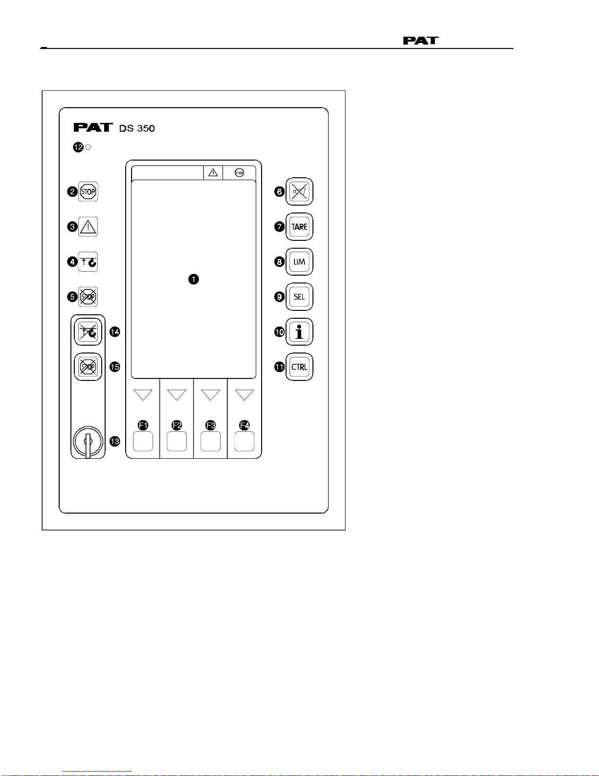
3.2 OPERATING CONSOLE............................................................................................. 5
3.3 CONTROL IDENTIFICATION ........................................................................................ 5
4CONFIGURATION SETUP...................................................................................... 11
4.1 LMI SETUP PROCEDURE........................................................................................ 11
4.2 QUICK SETTING OF THE REEVING ............................................................................. 15
4.3 QUICK HOIST LINE SELECTION................................................................................. 16
5 OPERATION......................................................................................................... 17
5.1 LIMIT SETTING ................................................................................................... 19
5.1.1 Slewing Angle Limitation / Work Area Definition.............................................. 20
5.1.2 Tip Height Limitation ................................................................................... 25
5.1.3 Boom Angle Limitation ................................................................................ 26
5.1.4 Radius Limitation........................................................................................ 28
5.2 INFO CRANE CONFIGURATION ................................................................................. 30
5.3 DISPLAY CONTRAST CONTROL ................................................................................ 31
6PRE-OPERATION INSPECTION AND CALIBRATION VERIFICATION ............................ 32
6.1 MACHINES WITH ONLY A MAIN HOIST......................................................................... 32
6.2 MACHINES WITH MAIN AND AUXILIARY HOISTS ............................................................. 32
6.3 INSTALLATION OF ANTI TWO-BLOCK RETAINER IN LOCKING POSITION ................................ 33
6.4 REMOVAL AND STORAGE OF THE ANTI TWO-BLOCK RETAINER ......................................... 33
6.5 PRE-OPERATION INSPECTION AND CALIBRATION VERIFICATION ........................................ 34
7 OPERATION......................................................................................................... 36
8SERVICE AND MAINTENANCE............................................................................... 37
9TROUBLESHOOTING ........................................................................................... 38
9.1 GENERAL .......................................................................................................... 38
9.2 MALFUNCTION TABLE ........................................................................................... 38
9.3 OPERATING ERRORS............................................................................................. 39
10 APPENDIX A: DETAILED SYMBOL EXPLANATION OF BOOM EXTENSIONS ............. 40
11 APPENDIX B: DETAILED SYMBOL EXPLANATION OF COUNTERWEIGHT OPTIONS .. 41












General Information
© PAT Rev. 7 06/18/01 // MO 191319_7.DOC
1
1 GENERAL INFORMATION
The PAT Load Moment Indicator1(LMI) DS 350 has been designed to provide the crane operator with
the essential information required to operate the machine within its design parameters.
Using different sensing devices, the Load Moment Indicator monitors various crane functions and
provides the operator with a continuous reading of the cranes capacity. The readings continuously
change as the crane moves through the motions needed to make the lift.
The LMI provides the operator with information regarding the length and angle of the boom, working
radius, rated-load and the total calculated-weight being lifted by the crane.
If non-permitted conditions are approached, the DS 350 Load Moment Indicator will warn the operator
by sounding an audible alarm, lighting a warning light and locking out those functions that may
aggravate the cranes condition.
2 WARNINGS
The LMI is an operational aid that warns a crane operator of approaching overload conditions and of
overhoist conditions that could cause damage to equipment and bodily injury.
The device is not, and shall not be, a substitute for good operator judgment, experience and use of
accepted safe crane operating procedures.
The responsibility for the safe crane operation shall remain with the crane operator who shall ensure
that all warnings and instructions supplied are fully understood and observed.
Prior to operating the crane, the operator must carefully and thoroughly read and understand the
information in this manual to ensure that the operation and limitations of indicator and crane are
known.
Proper functioning depends upon proper daily inspection and observance of the operating instructions
set forth in this manual. Refer to Section 6. Pre-Operation Inspection and Calibration Verification of
this manual.
The LMI can only work correctly, if all adjustments have been properly set. For correct
adjustment, the operator must answer thoroughly and correctly all questions asked during the
setup procedure in accordance with the real rigging state of the crane. To prevent material
damage and serious or even fatal accidents, the correct adjustment of the LMI has to be
ensured before starting the crane operation.
1LOAD MOMENT: generally the product of a force and its moment arm; specifically, the product of the load and the load-radius. Used in the
determination of the lifting capacity of a crane






Operator's Manual DS 350 / 1319
© PAT Rev. 7 06/18/01 // MO 191319_7.DOC
2
3 SYSTEM DESCRIPTION
The PAT Load Moment Indicator DS 350 consists of a central micro processor unit, operating
console, length/angle sensor, pressure transducers, and anti-two block switches.
The system operates on the principle of reference/real comparison. The real value, resulting from the
pressure measurement is compared with the reference data, stored in the central processor memory
and evaluated in the micro processor. When limits are reached, an overload warning signal is
generated at the operators console. At the same time, the aggravating crane movements, such as
hoist up, telescope out and boom down, will be stopped.
The fixed data regarding the crane, such as capacity charts, boom weights, centers of gravity and
dimensions are stored in memory chips in the central processor unit. This data is the reference
information used to calculate the operating conditions.
Boom length and boom angle are registered by the length/angle sensor, mounted inside the cable reel
which is mounted on the boom. The boom length is measured by the cable reel cable which also
serves as an electrical conductor for the anti two-block switches.
The crane load is measured by pressure transducers attached to the piston and rod side of the hoist
cylinders.
The interactive user guidance considerably simplifies the input of operating modes as well as the
setting of geometry limit values.






SYSTEM DESCRIPTION
© PAT Rev. 7 06/18/01 // MO 191319_7.DOC
3
Fig. 1: Components of the LMI system PAT DS 350
1 Anti Two-Block switches
2 Pressure Transducers
3 Length/Angle sensor
4 Operating console
5 Central-Micro-Processor unit






Operator's Manual DS 350 / 1319
© PAT Rev. 7 06/18/01 // MO 191319_7.DOC
4
3.1 SYSTEM FUNCTION
Upon switching on, the system starts with an
automatic test of the LMI system, of lamps
and audible alarm. During the test, the LC
display shows the initial logo.
If the system was turned off for more than
two hours, the setup configuration has to be
entered after the system test. ( Chapter4)
First, the operating mode is determined by
an interactive step-by-step interrogation of
the rigging states.
Next is the interactive input of the reeving.
Now the LC display shows in symbols all
inputs and awaits acknowledgment or
cancelling.
Upon acknowledgment of the inputs the
system is ready for operation.






SYSTEM DESCRIPTION
© PAT Rev. 7 06/18/01 // MO 191319_7.DOC
5
3.2 OPERATING CONSOLE
The console has 3 functions:
inputs by the crane operator (operating mode, reeving)
input of geometry limit values and signalization of exceeded limit values
display of important data and information
The operators console is mounted in the cranes cab in the operators field of vision. For a better
identification of displays and operating elements, they are continuously backlit during operation.
3.3 CONTROL IDENTIFICATION
This unit contains a display and different controls which are described as follows:
Legend to Fig 2:
1 LC Display Area 10 Button and Control Light "INFO"
2 Load Moment Limit Light 11 Button and Control Light "CONTROL"
3 Load Moment Prewarning Light 12 Audible Alarm
4 Alarm Light Anti-Two-Block 13 By-Pass Key Switch
5 Override Key Warning Light 14 Button and Control Light "By-Pass Anti-Two-Block"
6 Button Alarm Stop 15 Button and Control Light "By-Pass LMI shut-off
function"
7 Button and Control Light TARE F1 Button "Function 1"
8 Button and Control Light LIMITS F2 Button "Function 2"
9 Button and Control Light SELECT F3 Button "Function 3"
OPERATING MODE F4 Button "Function 4"






Operator's Manual DS 350 / 1319
© PAT Rev. 7 06/18/01 // MO 191319_7.DOC
6
Fig. 2: Operating Console





