C","'+.!#,DB'*+1#B,!
/!0+1!'234!5!!6786986:!88!).)! 67;<766!8!;=666>?@4AB)!
;!
1 GENERAL INFORMATION
The purpose of this service manual is to provide additional information to
assist a service or maintenance person in identifying malfunctions or
system problems with the PAT System. A digital voltmeter and regular
maintenance and service tools will be required to troubleshoot the system.
Note: Knowledge of how to use a digital voltmeter is assumed.
REFERENCE:
Operator’s Manual 056-065-190-005
Calibration Manual 031-300-190-009
Installation Manual 031-300-190-008
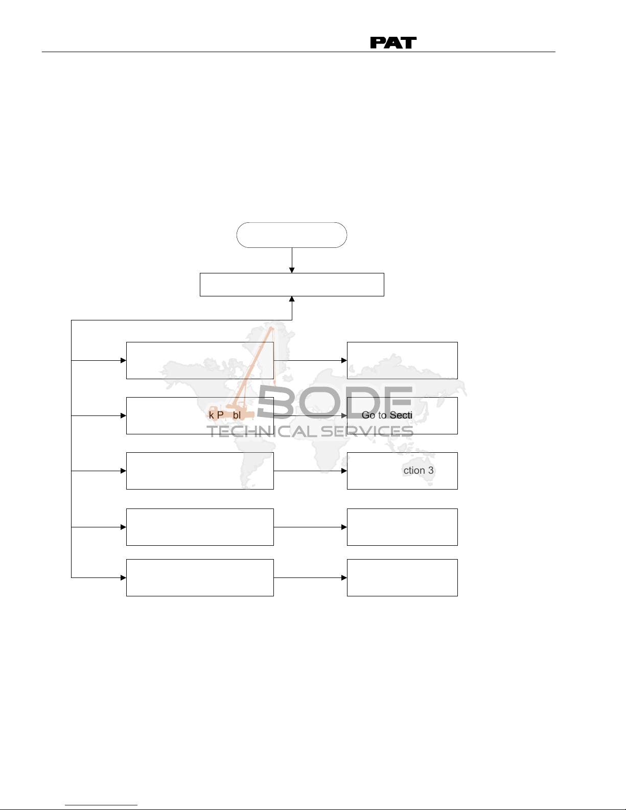
SYSTEM MALFUNCTION:
In case of a malfunction of the system, an error code
which identifies the system malfunction will be
displayed in the reeving portion of the display. The
error codes are listed in Section 4, Error Codes. The
table identifies various faults that can occur with
the EI65, explain each fault, and describe the action, which shall be taken
to correct the fault.
Faults within the electronic microprocessor shall be repaired by factory
trained service personnel. When these faults occur, contact your authorized
dealer or service organization.
If the operator identifies a possible problem in the system, perform the
pre-operation inspection Section 5 in the Operator’s Manual 056-065-190-005
to define the problem.
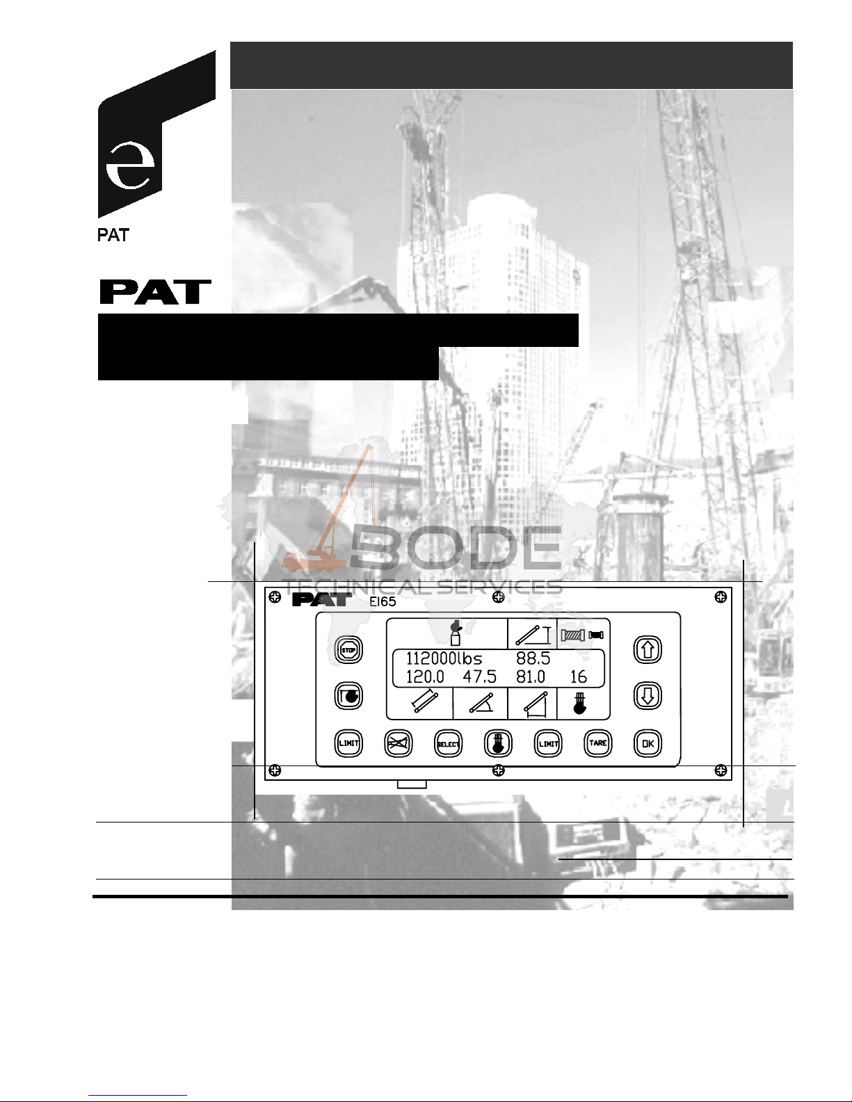
SYSTEM DESCRIPTION:
The PAT Length-Angle-Radius-Load Indicator System EI65 has been designed to
provide the crane operator with the essential information required to
enable the machine to be used within its design parameters. The EI65 System
indicates the length and angle of the boom, tip height, working radius and
the total weight being lifted by the crane. Using the various sensors and
the limits set by the operator, the EI65 System warns the crane operator of
certain approaching hazardous conditions which could occur during the
operation of his crane.
WARNING
Always refer to operational instructions and load charts provided by the crane
manufacturer for specific crane operation and load limits.
MB 115.0 J1 85.0
J2 50.0 0J 15.0
E71