PATTI QUANTUM Series User manual

PATTI®
Pneumatic Adhesion Tensile Testing Instrument
QUANTUM
SERIES
OPERATOR'S MANUAL
(OLD
OLD MODEL)

PATTI®
Pneumatic Adhesion Tensile Testing Instrument
QUANTUM
SERIES
OPERATOR’S MANUAL
(OLD
OLD MODEL)
MODEL PATTI® QUANTUM_____________
SERIAL NUMBER______________________
SOFTWARE VERSION__________________
SALES REPRESENTATIVE______________
DATE OF DELIVERY___________________
WARRANTY EXPIRATION DATE________

TABLE OF CONTENTS
Instrument Description............................................................................................................1
Cross-Sectional Schematics of Piston Assemblies..................................................................2
Safety Precautions...................................................................................................................3
Initial PA I® QUANTUM GOLD Software Installation Procedure*..................................5
PA I® QUANTUM GOLD Operation Procedure
I. Pre- est Preparation..............................................................................................7
A. Pull Stub Attachment...............................................................................7
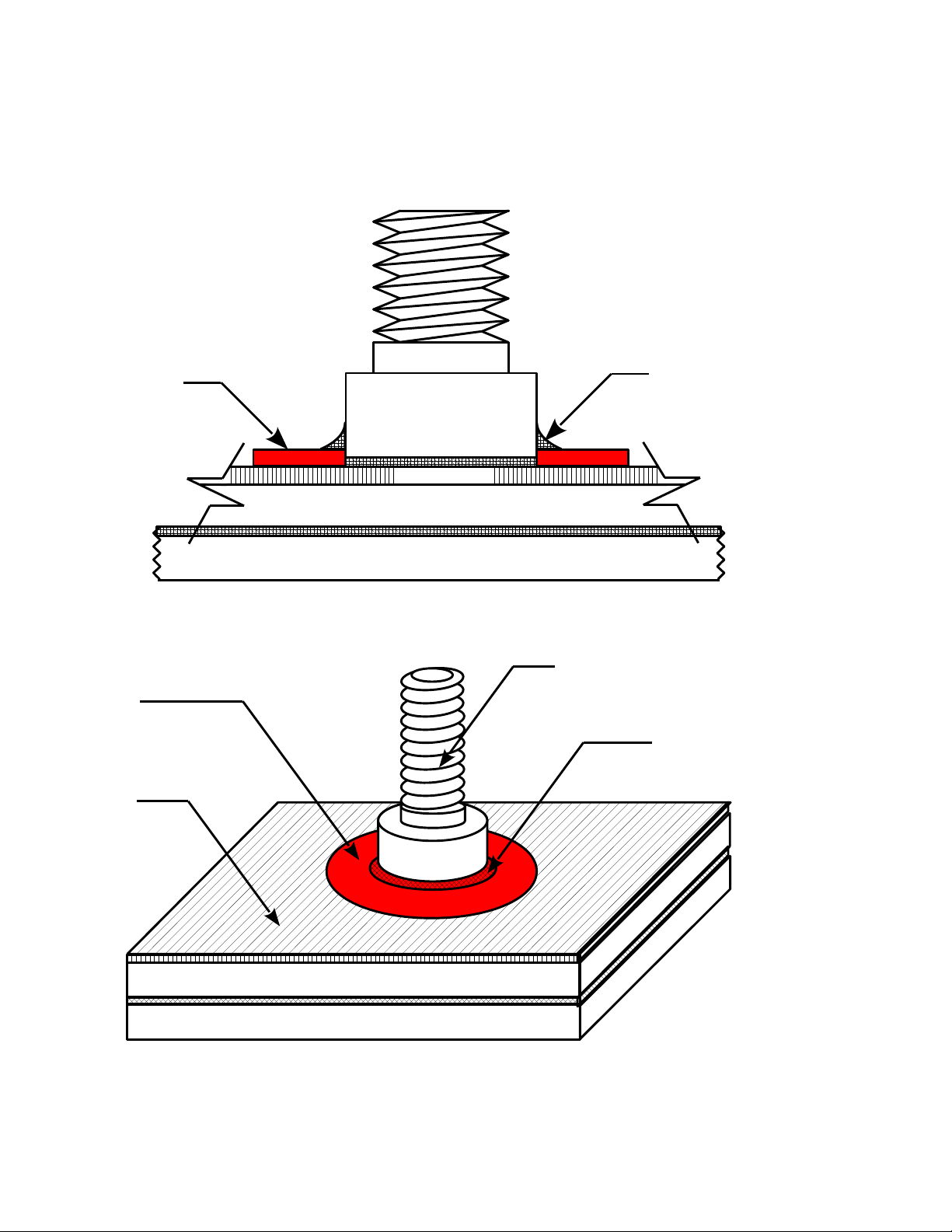
B. Cross-Sectional Schematics of Pull-Stub Adhered o Coating...............8
C. PA I® Connection Illustration............................................................10
D. Control Module Layout Illustrations.............................................11 & 12
E. Instrument Preparation............................................................................13
II. est Procedure....................................................................................................15
A. Control Module- est Surface Interfacing..............................................15
B. Control Module Operation.....................................................................16
C. PQGold Software Screenshot and Quick Reference Guide...................17
D. PQGold Software Suite Pre- est Setup.................................................18
E. PQGold Software Suite Post- est Operation...................................19 (5)
i. USB Camera Photo-documentation Procedure...................20 (8b)
ii. Generating a Report of the Pull- est....................................21 (8c)
*ONLY NEEDED IF ATTEMPTIN TO INSTALL THE PQ OLD SOFTWARE ON A
COMPUTER OTHER THAN THE ONE INCLUDED IN YOUR PACKA E!

TABLE OF CONTENTS (cont')
III. Post- est Instructions.........................................................................................22
A. Preparing for further testing..................................................................22
B. Close-out Procedure..............................................................................22
C. Analysis (for those not using PQGold Software Suite).........................23
Appendices
Frequently Asked Questions (FAQ) [Appendix A]....................................................25
Initial Bluetooth Configuration Instructions* [Appendix B].....................................27
AS M D4541 (page 1 included) [Appendix C].........................................................28
Piston Conversion able(s).........................................................................Appendix D
(reference only; software performs calculation)
Warranty & Warranty Registration..............................................................Appendix E
PQGold Software*..................................................................................Rear Binder Pocket
Software Quick Reference Sheet.........................................................................Rear Cover
*ONLY NEEDED IF ATTEMPTIN TO INSTALL THE PQ OLD SOFTWARE ON A
COMPUTER OTHER THAN THE ONE INCLUDED IN YOUR PACKA E!

INSTRUMENT DESCRIPTION
he PA I® system applies a true axial (relative to stub axis) tensile pull test. he tensile values
obtained quantitatively measure the bond between a paint, film, coating or adhesive and the substance
substrate. he PA I® conforms to AS M D4541, “Pull Off Strength of Coatings Using Portable Adhesion
esters,” and is listed in Annex A.4 as the only self-aligning, pneumatic instrument. he surface to be tested
can be smooth, rough, porous, flat or even curved and bond strengths of up to 10,000 psi can be tested with
the PA I® (using the F-20 piston). Advances in PA I® technology have been mainly customer-driven, so
custom applications are not only welcomed, but encouraged.
In a typical test, the first step is to properly attach a “pull-stub” to the test surface. Once the pull-stub
epoxy has cured, a self-aligning piston is attached to the pull-stub (see illustration on opposite page). he
control module is supplied with pressurized gas and then connected to the piston via a hose. he user slowly
increases the pressure to the piston until separation occurs between the pull-stub and the coating/test surface
(or until some predetermined pressure is reached). he control module will indicate the maximum pressure
applied to the piston, with or without pull-stub detachment. his burst pressure is then converted into tensile
strength (psi) by consulting a table for the appropriate piston and pull-stub. It is recommended that at least
three pull-tests are performed and statistically compared for a given surface before a definitive pull-off
pressure is assumed.
1

2
COATIN
SUBSTRATE
PULL-STUB
ASKET
ASKET
REACTION PLATE
ALL-THREAD ROD
KNURLED-KNOB
STAND-OFF RIN
(MAY DIFFER
FROM PICTURE)
PISTON BODY
PISTON PRESSURE
HOSE (BLUE)
ADHESIVE
STRAI HT CENTER HOLE
(NOT THREADED)
ASKET
CROSS-SECTIONAL SCHEMATICS
OF SELF-ALI NIN PISTON ASSEMBLIES
PULLIN FORCE REACTION PLATE
WITH THREADED
CENTER HOLE
PULL-STUB
COATIN
SUBSTRATE
PISTON
PRESSURE
HOSE
(BLUE)
ASKET
FI URE 1: STANDARD PISTON ASSEMBLY
FI URE 2: CONCRETE PISTON ASSEMBLY
PULLIN FORCE

SAFETY PRECAUTIONS
●Pull-Stub attachment
○Always follow the epoxy/adhesive manufacturer's instructions.
○Use latex gloves while mixing and applying adhesives to the test surface to avoid contact between
the adhesive and bare skin.
○A well-ventilated area is recommended when handling uncured adhesives.
●CO2 cartridges
○Keep cartridges out of direct sunlight.
○Do not expose cartridges to temperatures above 49 °C / 120 °F.
○Never dispose of full cartridges.
○Do not attempt to remove the CO2 cartridge holder from the control module if a CO2 cartridge is
installed in the holder and supply pressure gauge does not indicate 0 psi. Doing so will result in
rapid depressurization of remaining CO2 in cartridge!
●Prior to testing
○Safety goggles are recommended during each and every test.
○Do not apply pressures in excess of 150 psi to the supply air inlet.
○urn on the control module and ensure that the display indicates 0 psi (+/- 1 psi) before attaching
the blue piston hose to the piston outlet connection on the control module.
○Ensure that hose connections have been fully threaded or seated prior to performing a test.
●During testing
○Stand clear of the piston after it has been attached to the pull-stub due to the high pressures
present.
○Never attempt to open the control module as high pressures may be present. No internal user
adjustments are needed.
●After testing
○Do not attempt to remove the piston or any of the hose connections without properly
depressurizing the system according to the instructions in this manual.
●Battery precautions (9V and/or Laptop Battery)
○Do not store batteries in the control module if the unit will not be used for a long period of time.
○Do not dispose of in fire.
○Never attempt to short circuit or disassemble.
○Do not use if leakage is detected.
○Recycle or dispose of used batteries properly.
3

4

PATTI® QUANTUM OLD SOFTWARE INSTALLATION PROCEDURE
ONLY NEEDED IF ATTEMPTIN TO INSTALL THE PQ OLD SOFTWARE ON A
COMPUTER OTHER THAN THE ONE INCLUDED IN YOUR PACKA E!
System Requirements:
●Microsoft Windows enabled machine with Microsoft 2000 or later Operating System
(may not be compatible with Windows Vista)
●500 MB free Hard Drive space
●1 available USB port for basic operation (2 required if connecting the unit to your
computer via USB while using the USB camera simultaneously)
●OP IONAL: native Bluetooth capability or third party Bluetooth Dongle
(may be sold separately)
1. Identify the humb Drive that was packaged with your PA I® Quantum Gold. Insert it into a
USB port on your computer. Exit any other programs that are currently running.
Go to the Start menu and select My Computer. Double-click on the humb Drive folder labeled
PQ old vxxx. Navigate through the Installer folder and the Volume folder to double-click on
setup.exe to run the installer. It is recommended that you allow the software to install the
components in the default locations. Otherwise the App may not be able to find called
components when needed. Click Next.
2. Read and accept the National Instruments License Agreements. Click Next.
3. Wait for installation of the National Instruments software to complete. Note that this may take
20 minutes or longer depending on the speed of your computer.
Click Finish to exit the National Instruments Installer.
5. If you are using Windows XP and the USB camera drivers do not install automatically, locate
the MicroCapture folder on the humb Drive and click on setup.exe. Follow the steps
presented. he drivers will be automatically installed on Windows 7 machines.
6. Once you install this software package on another computer, you will need to register the ActiveX
controls to enable the imaging properties of the USB microscope. o do this, perform the
following steps (Windows 7):
a. Click start and type cmd in the search box. Do not press enter afterward.
b. In the window that appears, right-click on cmd.exe and choose Run as administrator.
c. Once at the command prompt, type the following exactly:
regsvr32 "C:\Program iles\P.A.T.T.I. Quantum Gold\data\IVDX.ocx"
hen press EN ER. You should receive a notification that the control was registered
successfully. If not, check the path by attempting to navigate to the control on your hard
drive.
5

PATTI® QUANTUM OLD SOFTWARE INSTALLATION PROCEDURE
d. Again, at the command prompt, type the following exactly:
regsvr32 "C:\Program iles\P.A.T.T.I. Quantum Gold\data\CamViewITaddons.ocx"
then press enter. you should receive a notification that the control was registered
successfully. if not, check the path by attempting to navigate to the control on your hard
drive. close the command prompt window.
7. Determine which COM Port your computer will use to communicate with the PA I®
Quantum Gold Control Module:
a. Go to the Start menu. Right-click on My Computer select Manage.
b. In the left-hand directory, left-click Device Manager to bring the contents into the
right-hand directory.
c. In the right-hand directory, click on the + sign next to Ports (COM & LPT) to expand
the contents of the directory.
i. o use the included USB--> RS232 Cable, look for the COM Port number that
corresponds to the selection titled Prolific... and record it for use later.
ii. o use Bluetooth (wireless data transmission) you may note the COM Port
number that corresponds to the selection titled Bluetooth Serial Port. However,
there are other settings that need to be configured properly to use Bluetooth. If
you are having problems connecting via Bluetooth, consult the Initial
Bluetooth Configuration Instructions (Appendix B) at the end of this manual.
8. You can use MAX (which will install a shortcut on your desktop) to rename your preferred
method of connecting to your P.A. . .I. Quantum Gold control unit. o do so, make sure that
your Bluetooth module is plugged in to your computer and properly installed or make sure that
you have run the driver installer for the USB-to-serial cable and have plugged it into your
computer first. Make sure that you have one method of connection ready before starting MAX.
Once MAX is running, you can select the first link in the center window and then rename your
connection method to something more appropriate. For instance, rename COM1 to Bluetooth,
for example. hen, when you run the PQGold App you will see a more descriptive name rather
than the COM port.
Before installing the software on a new computer, you may wish to visit our website at
www.adhesiontesting.com to see if a newer version of the software is available.
Full upgrade installation instructions can be found there as well.
Congratulations!
You are now ready to take full advantage of the features of the
PQ old Software Suite.
For Technical Support, please call (301) 975-9798 from 9am to 5pm EST
or email [email protected].
6

PATTI® QUANTUM OLD OPERATION PROCEDURE
I. Pre-test Preparation
A. Pull-Stub Attachment
NOTE: A clean pull-stub and clean surface are required for good adhesion. If a pull-stub
fails to adhere to your coating it is usually due to poor surface preparation! Even new pull-
stubs are not considered “clean” because a residue is left on the pull-stub after
sandblasting. Any standard method for cleaning/degreasing aluminum can be used on the
pull stubs and mild solvents should be fine on your coating. he cleaned surface should not
be handled to prevent contamination from skin oils, etc. Do not reuse pull-stubs unless the
residual adhesive has been thoroughly removed and the cleaned surface restored.
Use cleaned pull-stubs within 24 hours for best results.
WARNIN : Always follow the epoxy/adhesive manufacturer's instructions. Use latex
gloves while mixing and applying adhesives to the test surface to avoid contact between
the adhesive and bare skin. A well-ventilated area is recommended when handling uncured
adhesives.
1. Prepare adhesive for application as recommended by the manufacturer.
2. If using adhesive masks (rather than cut-off rings), apply the mask to the location you
wish to test. Care should be taken not to touch the coating exposed in the center of the
mask (see note above).
3. Carefully apply enough adhesive to cover an area the size of a pull-stub on the coating
or test surface (in the center of the adhesive mask, if applicable). Also, apply a small
amount of adhesive to the flat, sandblasted surface of the stub head. Work the epoxy into
the roughened surface to fill the voids. Avoid depositing adhesive onto the stub threads.
4. Press the flat surface of the stub head against the epoxied area on the coating or test
surface. If using an adhesive mask, place the flat surface of the pull-stub onto the coating
in the center of the mask. Gently slide the stub around to ensure that it is in the center.
NOTE: Minimize any rotation, tilting, or sliding of pull-stub with respect to test coating
after contact is made, as this may introduce voids at the adhesive-test surface interface.
Although some movement is recommended when using the adhesive masks, try to disturb
the stub as little as possible once contact with the surface has been made.
7
8
PULL-STUB
SUBSTRATE
BACKIN PLATE (IF REQUIRED)
COATIN
FIGURE 2a
ADHESIVE
MASK
ADHESIVE
MASK
COATIN
SUBSTRATE
BACKIN PLATE (IF REQUIRED)
SUBSTRATE
EXCESS EPOXY
DISPLACED BY
ADHESIVE MASK
CROSS-SECTIONAL SCHEMATICS
OF PULL-STUB ADHERED TO COATIN
USIN ADHESIVE MASKS
FIGURE 2b
PULL-STUB
EXCESS EPOXY
DISPLACED BY
ADHESIVE MASK

PATTI® QUANTUM OLD OPERATION PROCEDURE (cont')
5. If you cannot use adhesive masks for some reason or simply prefer the older cut-off
rings, now is the time to utilize them. While holding the stub in place, press a cut-off
ring (knife edge towards test surface) around the stub and through the adhesive to the
coating or test surface.
NOTE: he use of either a cut-off ring or adhesive mask is very important. It displaces the
excess adhesive from the stub which reproduces the test area. his not only eliminates the
need for scoring or wiping, but ensures that the adhesive-test surface interface area is well-
defined. his allows for an accurate tensile strength conversion.
NOTE: A light clamping pressure (or weight) maintained on the stub during adhesive
curing will produce a stronger glue joint. his is optional.
6. Allow for the passage of a sufficient amount of adhesive cure time as specified by the
adhesive manufacturer.
NOTE: For most adhesives it is recommended that a cure time of at least 24 hours is
provided prior to pull testing. For a faster test, inquire about the P.I.P.S. (PA I Instant
Pull-Stubs) system. he PIPS system uses a light-cure adhesive and high-intensity
flashlight to allow for 5 minute tests! Ask your distributor.
9

10
PATTI® QUANTUM DIGITAL/GOLD CONNECTION ILLUSTRATION
TO WHITE SNAP-IN CONNECTOR
150 PSI IN MAX
TO GOLD THREADED CONNECTOR
AIR CYLINDER
REGULATOR
SOLD SEPARATELY;
CALL FOR DETAILS
AIR CYLINDER
OR SHOP AIR
(NOT REQUIRED IF
USING CO2 CARTIRDGES)
PISTON
FRONT PANEL
OF PATTI
REAR PANEL
OF PATTI
120 VAC
(NOT REQUIRED IF
USING 9V BATTERY)
TO BATTERY BOX
9V BATTERY
(NOT REQUIRED IF
USING 120 VAC POER)
GENUINE INNOVATIONS
16 g CO2 CARTRIDGE
PART #2062
(NOT REQUIRED IF
USING AIR CYLINDER
OR SHOP AIR)
GENUINE INNOVATIONS
CARTRIDGE HOLDER

11
Peak
Reset
PATTI
QUANTUM
GOLD
Supply
Pressure
Power
On/Off
Ad esion Tester
Piston Pressure
150 psi MAX In 12 VDC
Piston Out
9V
Serial Port
BATTERY
LIFT TO WITHDRAW
PSI
FRONT PANEL VIE
REAR PANEL VIE
PATTI® QUANTUM OLD CONTROL MODULE LAYOUT

12
Rate Run
CO2
ATTENTION: USE ONLY
GENUINE INNOVATIONS
16g CO2 CARTRIDGES!
GI PART #2062
Bluetoot
Serial
TOP-DO N VIE
PATTI® QUANTUM OLD CONTROL MODULE LAYOUT

PATTI® QUANTUM OLD OPERATION PROCEDURE (cont')
B. Instrument Preparation
1. Ensure that the unit has power by using one of the following two methods:
a. Place a 9V battery in the BATTERY slot on the rear panel of the unit.
Note that (1) new 9V battery shipped with your unit.
-OR-
b. Plug the included AC Adapter into a 120 VAC wall outlet. Plug the other end of
the adapter into the lower right hand-corner of the rear panel of the unit labeled
9 VDC.
2. urn on the PA I® QUANTUM GOLD by operating the Power On/Off rocker
switch on the left side of the front panel of the unit.
3. Pressurize the system using one of the following three methods:
CAUTION: Do not exceed 150 psi input pressure! Doing so may damage the gauges
and/or result in rupture of the internal hoses leading to expensive repairs!
a. High pressure bottled gas or any clean, constant inert gas supply
(i.e. Nitrogen [N2], Carbon Dioxide [CO2], filtered air, etc.)
i. Attach correct end of yellow hose to the threaded 150 psi MAX In air
connection on the lower left-hand side of the rear panel of the unit.
ii. Attach other end of yellow hose to gas supply regulator.
iii. Open gas high pressure valve and turn regulator valve handle clockwise
to produce a supply pressure between 100 psi (690 KPa) and 150
(1035 KPa) psi as read on the gauge. Remember, do not exceed 150 psi!
b. CO2 Cartridge
i. Place a CO2 cartridge into the black cartridge holder, spherical end first.
NOTE: It is impossible to pierce the CO2 cartridge if it is not inserted into
the cartridge holder in the correct orientation.
ii. hread the cartridge holder onto the gray threaded adapter labeled CO2
(located on the top of the unit) until the cartridge is pierced and gas flows
audibly into the Control Module.
NOTE: he PA I® QUANTUM is equipped with an internal regulator to
prevent overpressurization when charging the unit with a CO2 cartridge.
13

PATTI® QUANTUM OLD OPERATION PROCEDURE (cont')
c. PATTI® Air Pump
CAUTION: he PA I® QUANTUM must be configured correctly to be used in
conjunction with the PA I® Air Pump. If a PA I® Air Pump was not included in
your original package, please contact the manufacturer before attempting to use one
with your unit.
NOTE: Generally speaking, a supply pressure of at least 100 psi is needed for a
successful pull. However, you may find that this number is higher or lower depending
on your piston size. If you start a test and run out of supply air, you may obtain
inaccurate tensile strength measurements when continuing the same test with
replenished air.
i. Attach correct end of yellow hose to the threaded 150 psi MAX In air
connection on the lower left-hand side the rear panel of the unit.
ii. urn on PA I® Air Pump compressor.
iii. When Supply Pressure gauge on the right-hand side of the front panel
reads approximately 140 psi, turn off PA I® Air Pump compressor.
Remember, do not exceed 150 psi!
4. In the upper left-hand corner of the rear panel of the unit, identify the white Piston Out
connector. Push the metal spring fitting to the right until it clicks.
5. Snap the white connector of the blue hose into the Piston Out connection.
6. If using the included USB-->RS232 cable, connect the USB portion of the cable to an
available USB port on your computer. Your computer should automatically detect the
hardware. Connect the orange mini-adapter end of the cable to the back panel of the
control module via the Serial Port.
If using Bluetooth, no connections are needed at this time.
14

PATTI® QUANTUM OLD OPERATION PROCEDURE (cont')
II. Test Procedure
A. Control Module-Test Surface Interfacing
1. Remove clamp or weight from pull-stub (if applicable).
2. Carefully remove the cut-off ring from the pull-stub (if applicable).
wo possible methods for doing this are as follows:
NOTE: Remove the cut-off rings very carefully to disturb the pull-stub adhesive as little as
possible. his will produce the most accurate results.
his step can be skipped entirely if using our adhesive masks!
a. Using a utility knife, carefully cut down through the cut-off ring and to the coating
or test surface (preferred method).
b. Using a pair of slip-joint pliers, squeeze the sides of the ring and gently twist to
break the cut-off ring away from the adhesive.
3. Separate the piston body (“bottom” of piston) from the reaction plate (“top” of piston),
exposing the gasket. Ensure that the gasket is free of dirt and other debris.
4. Place the piston body over the pull-stub, with the felt side resting on the coating or test
surface and the gasket visible.
5. hread the Reaction Plate clockwise onto the pull-stub until light contact is made with the
piston body.
NOTE: Do not tightly thread the Reaction Plate to the pull-stub. Doing so may weaken the
adhesive bond between the pull-stub and the test surface and may even break the pull-stub
from the surface!
6. Reverse thread the Reaction Plate counter-clockwise about one-quarter (¼) turn to allow
gasket sealing and alignment of Reaction Plate perpendicular to axis of pull-stub.
7. Connect the blue hoses by threading the connector on the end of the blue hose from the
piston to the threads on the end of the blue hose to the Control Module.
15

PATTI® QUANTUM OLD OPERATION PROCEDURE (cont')
B. Control Module Operation
WARNIN : It is recommended that safety goggles be worn during each and every test. Use
extreme caution during testing. Piston recoil will occur upon pull-stub-sample separation.
Stand clear of the piston after it has been attached to the pull-stub and before conducting your
pull test.
1. urn on the PA I® QUANTUM GOLD by operating the Power On/Off rocker switch
on the left side of the front panel of the control module.
2. Ensure that the Piston Pressure display in the center of the front panel of the unit reads
zero (0) psi (+/- 1 psi). If not, open the Rate valve by turning the Rate Valve Knob on the
left-hand side of the top of the unit counter-clockwise about a half turn. hen push the
Peak Reset button on the right-hand side of the front panel.
3. If Step 2 above does not bring the display to zero, identify the lone screw on the bottom on
the unit. hread the screw into the control module until the display zeroes, then back the
screw off again.
4. Close the Rate Valve by turning the Rate Valve Knob clockwise until finger tight.
CAUTION: he closed position of the Rate valve knob is finger tight. It is not intended for
shut-off service! Repeated over-rotation (clockwise) of this knob will cause permanent
damage to the valve seat and is not covered by the warranty.
DAMA E TO RATE VALVE WILL REQUIRE FACTORY SERVICIN
AT OWNER'S EXPENSE.
5. If using conversion charts rather than the bundled software suite, skip to Step 5 on page
13.
If using the PA I® QUANTUM GOLD Software application, follow steps a-f on the
following two pages (17 & 18).
16
This manual suits for next models
1
Table of contents


