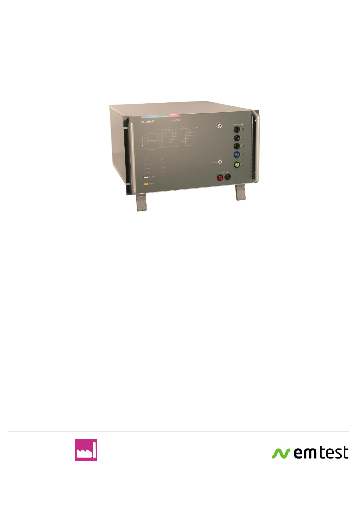
EMTEST CNI 503 Series Technical Document
Manual
f o r O p e r a t i n g
CNI 503 / CNI 501
3-phase coupling decoupling network
CNI 503x
CNI 503 A series
CNI 503 B series
1-phase coupling decoupling network
CNI 501x
Testing of electronic modules with EFT/burst, 1.2/50s Surge or
Ring Wave pulses up to 10kV, 5kA
The CNI 503 couples the surge and burst pulses from the
impulses generators UCS 500Nx to a three phase test object
(coupling as per. IEC or ANSI standard).
The CNI 503 is controlled from EM Test transient generator of
the Series 500 (UCS 500Nx, VCS 500Nx, EFT 500Nx).
Burst, Surge and
Ringwave Pulse as per.
–IEC 61000-4-4
–IEC 61000-4-5
–IEC 61000-4-12
–ANSI
Version:
3.32 / 28.06.2016
the benchmark for emc
Replaces:
3.31 / 14.06.2016
Filename:
UserManual-CNI503-E-V3.32.doc
Printdate:
28.06.16

EM TEST CNI 501 / CNI 503
Manual of operation V 3.32 2 / 41
EM TEST (Switzerland) GmbH
Sternenhofstrasse 15
4153 Reinach BL1
Switzerland
Phone : +41 61 717 91 91
Fax : +41 61 717 91 99
URL : http://www.emtest.com
Copyright © 2016 EM TEST (Switzerland) GmbH
. All right reserved.
Specifications subject to change

EM TEST CNI 501 / CNI 503
Manual of operation V 3.32 3 / 41
Contents
1. List of coupling networks.............................................................................................................................5
1.1. Coupling networks for IEC pulses.........................................................................................................5
1.2. Coupling networks as per IEC, ANSI and Ringwave............................................................................6
1.3. Special Coupling networks....................................................................................................................7
2. Operating Functions .....................................................................................................................................8
2.1. Front view..............................................................................................................................................8
2.2. Rear side...............................................................................................................................................9
2.3. CNI 501 S1..........................................................................................................................................10
3. General .........................................................................................................................................................11
3.1. Coupling modes ..................................................................................................................................11
3.2. Coupling to Signal Lines .....................................................................................................................11
4. Technical Data CNI 503 ................................................................................................................................12
4.1. EUT power supply...............................................................................................................................12
4.2. DC current capability of CNI 503Nx....................................................................................................13
4.3. Technical data special CNI 503 ..........................................................................................................14
4.4. General................................................................................................................................................15
4.5. Test level with Burst as per IEC 61000-4-4 Ed.2................................................................................16
4.6. Decoupling inductors for surge pulse..................................................................................................16
5. Operation......................................................................................................................................................17
5.1. Power supply input (EUT)...................................................................................................................17
5.2. Synchronization...................................................................................................................................17
5.3. Connection of DC Equipment..............................................................................................................18
5.4. Operation with CNI coupler or generator internal CDN ......................................................................19
6. Test set up....................................................................................................................................................20
6.1. Grounding............................................................................................................................................21
6.2. Surge coupling to CNV504 / 508 network for surge to signal- and data-lines....................................22
6.2.1. Burst coupling to HFK capacitive coupling clamp for signal- and data lines ......................................22
6.3. Test setup CNI 503 with UCS500N5E and UCS500N5V generators.................................................23
6.4. Test setup CNI 501 / 503 with EFT 500/800 and VCS 500 generators..............................................24
6.5. test setup with CNI 501 BS3 or CNI 503B7.5.....................................................................................25
7. ANSI Coupling (option)...............................................................................................................................26
8. CNI 503 Rack Mountain...............................................................................................................................27
9. Special coupling networks.........................................................................................................................28
9.1. CNI 501B9...........................................................................................................................................28
9.1.1. Operating elements.............................................................................................................................28
9.1.2. Technical Data ....................................................................................................................................29
9.1.3. AC Application.....................................................................................................................................29
9.1.4. DC Application.....................................................................................................................................30
9.1.5. Schematics..........................................................................................................................................30
10. Maintenance and calibration......................................................................................................................31
10.1. General................................................................................................................................................31
10.2. Calibration and Verification.................................................................................................................31
10.2.1. Factory calibration..........................................................................................................................31
10.2.2. Guideline to determine the calibration period of EM Test instrumentation ....................................31
10.2.3. Calibration of Accessories made by passive components only:....................................................31
10.2.4. Periodically In-house verification....................................................................................................31
11. Delivery Groups...........................................................................................................................................32
11.1. Basic equipment..................................................................................................................................32
11.2. Accessories and options .....................................................................................................................32

EM TEST CNI 501 / CNI 503
Manual of operation V 3.32 4 / 41
12. Appendix ......................................................................................................................................................33
12.1. Declaration of CE-Conformity .............................................................................................................33
12.2. Connectors..........................................................................................................................................34
12.2.1. 32 A plugs and connectors 4mm from Multi Contact .....................................................................34
12.2.2. 100 A plugs and connectors 6mm from Multi Contact ...................................................................34
12.2.3. Multi Contact MC Locking system (AR-system).............................................................................35
12.2.4. 100 A DC plugs and connectors from Multi Contact......................................................................35
12.3. General diagram ................................................................................................................................36
12.4. Inrush current.....................................................................................................................................41

EM TEST CNI 501 / CNI 503
Manual of operation V 3.32 5 / 41
1.
List of coupling networks
1.1.
Coupling networks for IEC pulses
Device
Impulse Phase Supply rated Current ac
Remarks
CNI 501
5.5kV 1 250V 32A
48V/32A dc
CNI 501 S1
5.5kV 1 250V 100A
75V/100A dc
CNI 503 A
5.5kV 3 3x480V 16A
CNI 503 A2
5.5kV 3 3x480V 32A
CNI 503 A3
5.5kV 3 3x480V 63A
RACK required
CNI 503 A4
5.5kV 3 3x480V 100A
RACK required
CNI 503 A4.1
5.5kV 3 3x440V 100A
EN 50121-4
CNI 503 A5
7kV 3 3x480V 16A
CNI 503 A7
7kV 3 3x480V 32A
CNI 503 A8
7kV 3 3x480V 63A
RACK required
CNI 503 A9
7kV 3 3x480V 100A
RACK required
CNI 503 A10
8kV 3 3x480V 16A
CNI 503 A12
8kV 3 3x480V 32A
CNI 503 A13
8kV 3 3x480V 63A
RACK required
CNI 503 A14
8kV 3 3x480V 100A
RACK required
CNI 503 A16
10kV 3 3x480V 16A
CNI 503 A18
10kV 3 3x480V 32A
CNI 503 A19
10kV 3 3x480V 63A
RACK required
CNI 503 A20
10kV 3 3x480V 100A
RACK required

EM TEST CNI 501 / CNI 503
Manual of operation V 3.32 6 / 41
1.2.
Coupling networks as per IEC, ANSI and Ringwave
Device
Impulse Phase Supply rated Current ac
Remarks
CNI 503 B5
7kV 3 3x480V 16A
CNI 503 B7
7kV 3 3x480V 32A
CNI 503 B8
7kV 3 3x480V 63A
RACK required
CNI 503 B9
7kV 3 3x480V 100A
RACK required
Device
Imp Phase Supply AC
Remarks
CNI 501 B9
7kV 1 AC 250V 100A
DC 75V 100A
- IEC 61000-4-5, ANSI/IEEE C62.41
- TEST ON function (possibility for Emergency Switch and
no Warning lamp control!!!)
CNI 503 B7.2
7kV 3 AC 3x480V 32A
DC 1000V 32A
- IEC 61000-4-5, ANSI/IEEE C62.41
- No TEST ON function (no possibility for an
Emergency Switch and no Warning lamp control!!!)
CNI 503 B7.3
7kV 3 AC 3x480V 32A
DC 1000V 32A
- IEC 61000-4-5, ANSI/IEEE C62.41
- TEST ON function (possibility for Emergency Switch and
Warning lamp control)
- Needs a rack to be ordered separately
CNI 503 B7.4
7kV 3 AC 3x690V 32A
DC 1000V 32A
- IEC 61000-4-5, ANSI/IEEE C62.41
- No TEST ON function (no possibility for an
Emergency Switch and no Warning lamp control!!!)
- Needs a UCS 500N7.2 or UCS 500N7.7
CNI 503 B7.5
7kV 3 AC 3x690V 32A
DC 1000V 32A
- IEC 61000-4-5, ANSI/IEEE C62.41
- TEST ON function (possibility for Emergency Switch and
Warning lamp control)
- Needs a UCS 500N7.2 or UCS 500N7.7 and a rack
CNI 503 B9.2
7kV 3 AC 3x480V 100A
DC 1000V 100A
- IEC 61000-4-5, ANSI/IEEE C62.41
- No TEST ON function (possibility for Emergency Switch
and Warning lamp control)
- Needs a rack to be ordered separately
CNI 503 B9.6
7kV 3 AC 3x480V 100A
DC 1000V 100A
- IEC 61000-4-5, ANSI/IEEE C62.41
- TEST ON function (no possibility for an
Emergency Switch and no Warning lamp control!!!)
- Needs a rack to be ordered separately
Coupling networks for the US are generally specified for a 3 phase power mains supply of 3x480Vrms.
It is forbidden to disconnect the plug in DC operation under voltage.
Risk of a stationary spark!

EM TEST CNI 501 / CNI 503
Manual of operation V 3.32 7 / 41
1.3.
Special Coupling networks
Device
Impulse Phase Supply rated Current ac
Remarks
CNI 503 A.1
5.5kV 3 3x690V 16A
needs a UCS 500N5.2
CNI 503A S1
5.5kV 3 3x690V 16A
CNI 503A S2
5.5kV 3 3x690V 32A
CNI 503 A2.1
5.5kV 3 3x690V 32A
needs a UCS 500N5.2
CNI 503 A2.2
5.5kV 3 3x480V / DC 1000V 32A
No TEST ON function
CNI 503 A2.6
5.5kV 3 3x480V / DC 1000V 32A
With TEST ON function
500 VDC / 150 A
CNI 503A2.10
5.5kV 3 3x690V / DC 1000V 32A
No TEST ON function
CNI 503A3.1
5.5kV 3 3x690V 63A
requires MRAC or RAC 1000V dc
CNI 503A S3
5.5kV 3 3x690V 63A
requires MRAC or RAC
CNI 503A S4
5.5kV 3 3x690V 100A
requires MRAC or RAC
CNI 503B S1
7kV 3 3x690V 16A
CNI 503B S2
7kV 3 3x690V 32A
CNI 503B S3
7kV 3 3x690V 63A
requires MRAC or RAC
CNI 503B S4
7kV 3 3x690V 100A
requires MRAC or RAC
CNI 503B S7
7kV 3 3x208V 32A 400Hz
Burst 6.0kV
CNI 503 A14.1
8kV 3 3x480V 100A
requires Rack 32 or 34 UH
CNI 503 A12 S2
8kV 3 3x690V 32A
IEC @ANSI-B coupling (manual)
CNI 503 A16 S1
10kV 3 3x690V 16A
CNI 503A S22
4.4kV 3 3x480V 200A
requires MRAC or RAC
CNI 501B S3
7kV 1 250V 1000 VDC 32A
Ohne Test ON Function,
CNI 501 S4
10kV 1 250V 10A
CNI 501 S6
10kV 1 250V 16A
Generator impedance 2Ω
EM TEST CNI 501 / CNI 503
Manual of operation V 3.32 8 / 41
2.
Operating Functions
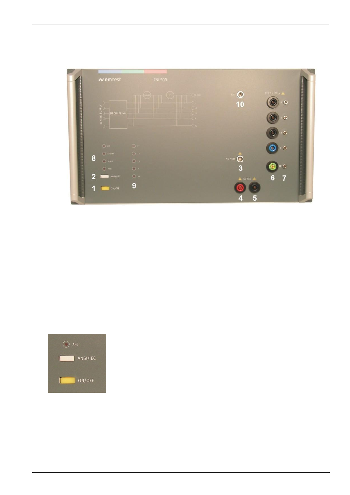
2.1.
Front view
Figure 2.1: CNI 503 font view ( model for 4kV )
1"TEST ON
2Switching ANSI -IEC
3EFT output to HFK coupling clamp
4HV output for ext. surge coupling networks
5COM output for ext. surge coupling networks
6DUT Output L1/DC+, L2, L3, N/DC-, PE
7Earth plug for EFT burst verification
8LED display Pulse (EFT / 50HFK / Surge)
9LED display couplings
10 EFT input from UCS 500Mx / EFT 500/800
1 Button Test On
Press this button to connect the power mains supply to the EUT via the built in relay switch. The yellow light in the button
indicates the switched mains to the EUT.
2 Button ANSI / IEC (Option)
This button changes the coupling between ANSI coupling and IEC coupling.
LED disabled: IEC coupling 2L-L or L-N 10L-PE, N-PE
LED enabled: ANSI coupling 2all couplings
EM TEST CNI 501 / CNI 503
Manual of operation V 3.32 9 / 41
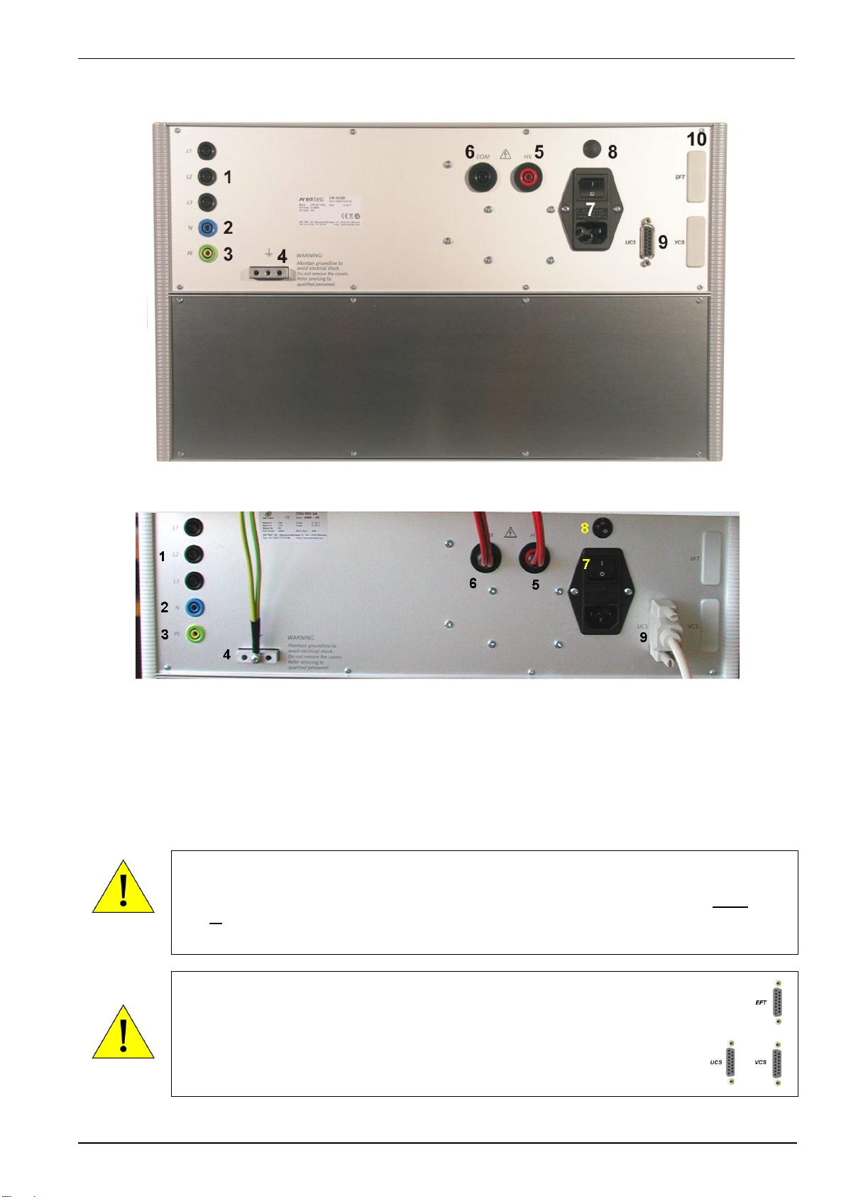
2.2.
Rear side
Figure 2.2: Rear side CNI 503 (4kV version)
Figure 2.3: CNI 503 Rear side (> 4kV version)
1EUT power L1, L2, L3
2EUT power N
3EUT power PE
4Ground Reference
5HV Input from generator
5HV Input from generator
6COM Input from generator
7 Power switch with fuse
8Voltage selector 230V / 115V
9 CN control input from UCS generator
10 CN control input from EFT and or VCS generator
If the CNI 503 includes two or more CN interfaces for UCS500NE and UCS500NV, only one
generator is allowed to communicate to the CNI 503. In case that all remote control input, for UCS
(9) and EFT/VCS (10), are included in the CNI 503 the operator has to take care that either the
UCS or the EFT/VCS is controlling the CNI.
A simultaneous operation by more than one generators is not allowed.
The CN control input is available in two different versions.
- Interface to generators of the series UCS 500xx
- Interface to generators of the series EFT 500x and or VCS500x
The connectors have different pin configurations. Therefore each generator
must be plugged in as signed at the rear panel.
EM TEST CNI 501 / CNI 503
Manual of operation V 3.32 10 / 41
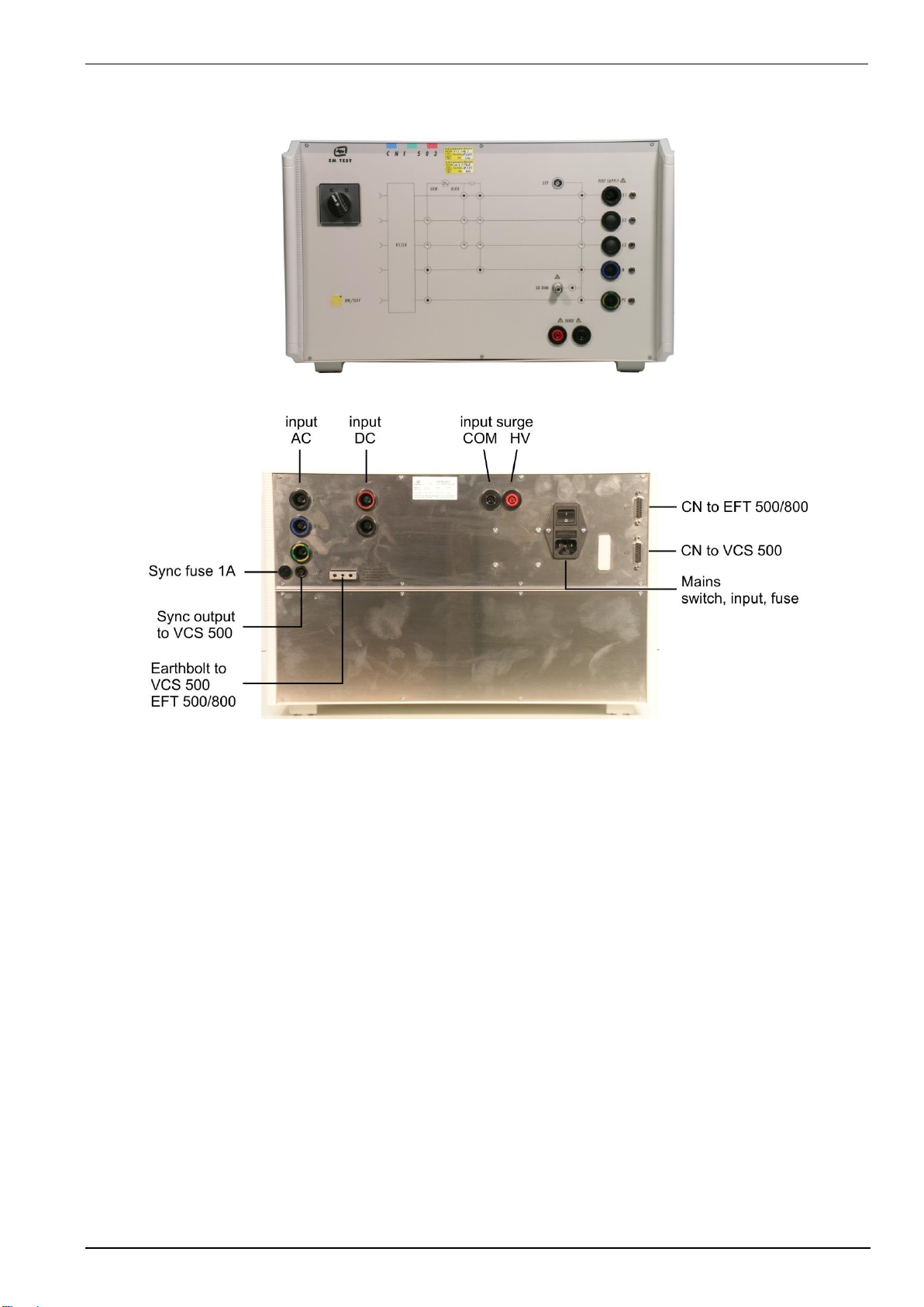
2.3.
CNI 501 S1
Figure 2.3: Front side CNI 501 S1 with AC / DC switch
Figure 2.4: CNI 501 S1 rear side
EM TEST CNI 501 / CNI 503
Manual of operation V 3.32 11 / 41
3.
General
The coupling network has to couple the transients well defined to the lines of a power supply system. The coupling is
realized by discrete coupling capacitors, having a sufficient voltage capability and bandwidth. The specification is
given in IEC 61000-4-4, IEC 61000-4-5, IEC 61000-4-12 and ANSI.
There are different coupling network models available:
Model
Burst
Surge IEC
Surge ANSI
Ringwave
CNI 503B
X
X
X
X
CNI 503A
X
X
--
--
CNV 503
--
X
--
--
CNE 503
X
--
--
--
CNI 501
X
X
--
--
The coupling/decoupling network is divided in two parts:
- The decoupling and filtering unit
- The coupling unit
The decoupling unit has to
-To decouple the low impedance power mains supply from the test setup.
-protect other equipment which is connected to the power mains supply
But which is not part of the test set-up.
The coupling network superimposes the transients to the lines of a power supplysystem, AC as well as DC supply.
3.1.
Coupling modes
The test can be conducted with different coupling modes.
61000-4-5 Surge immunity requirements
- Line or lines to protective earth (unsymmetrical) e.g. L1-PE; L1+L2+L3+N-PE
- Line to Line (symmetrical) e.g. L1-L2 or L3-N
61000-4-4 Electrical fast transients
Line or lines to reference ground. All combinations are possible. The protective earth (PE) is regarded as equal to
all other lines and therefore is tested as all other lines
3.2.
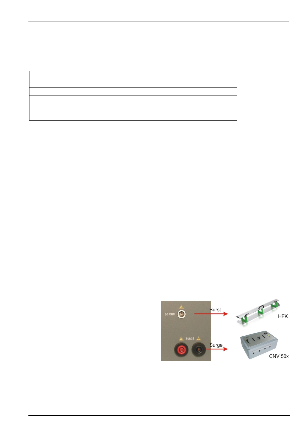
Coupling to Signal Lines
The coupling to I/O lines is generally realized with other
coupling networks than used for power supply lines. The
loading of the I/O lines with big coupling capacitors is
mostly not possible. The data transmission may be
disturbed
For coupling to I/O lines special couplers acc. to IEC
61000-4-5 are available, such as the CNV 504 and the
CNV 508 for four respectively for eight wire systems. For
coupling the EFT transient to signal lines the capacitive
coupling clamp is used. The clamp can also be
connected and controlled via the CNI 503 networks but
normally shall be connected directly to the coaxial output
of the generator itself.
Figure 3.1: External device plug for Burst and Surge

EM TEST CNI 501 / CNI 503
Manual of operation V 3.32 12 / 41
4.
Technical Data CNI 503
4.1.
EUT power supply
Pulse peak
Coupling network
EUT supply 50/60Hz
Remarks
voltage
IEC, ANSI,
Ringwave
IEC
Voltage Current ac/dc
ac dc
5.5kV
CNI 501
1x250V 32A
dc 48V/32A
CNI 501 S1
1x250V 100A
dc 75V/100A
5.5kV
CNI 503 A
3x480V 16A
CNI 503 A2
3x480V 32A
CNI 503 A2
3x480V 32A
dc 1000V 32A
CNI 503 A3
3x480V 63A
requires MRAC or RAC
CNI 503 A4
3x480V 100A
requires MRAC or RAC
CNI 503 A5 S22
3x480V 200A
requires MRAC or RAC
CNI 503 A2.10
3x690V, 1000V 32A
No Test ON
CNI 503 A S1
3x690V 16A
CNI 503 A S2
3x690V 32A
CNI 503 A S3
3x690V 63A
requires MRAC or RAC
CNI 503 A S4
3x690V 100A
requires MRAC or RAC
7kV
CNI 503 B5
CNI 503 A5
3x480V 16A
CNI 503 B7
CNI 503 A7
3x480V 32A
CNI 503 B7.2
3x480V, 1000V 32A
No Test ON
CNI 503 B7.3
3x480V, 1000V 32A
Test ON, need MRAC or RAC
CNI 503 B7.4
3x690V, 1000V 32A
No Test ON, need MRAC or RAC
CNI 503 B8
CNI 503 A8
3x480V 63A
requires MRAC or RAC
CNI 501 B9
250V, 75V 100A
6 HU, Test ON
CNI 503 B9
CNI 503 A9
3x480V 100A
requires MRAC or RAC
CNI 503 B9.2
3x480V, 1000V 100A
No Test ON, need MRAC or RAC
CNI 503 B9.6
3x480V, 1000V 100A
Test ON, need MRAC or RAC
CNI 503 B S1
3x690V 16A
CNI 503 B S2
3x690V 32A
CNI 503 B S3
3x690V 63A
requires MRAC or RAC
CNI 503 B S4
3x690V 100A
requires MRAC or RAC
8kV
CNI 503 A10
3x480V 16A
CNI 503 A12
3x480V 32A
CNI 503 A13
3x480V 63A
requires MRAC or RAC
CNI 503 A14
3x480V 100A
requires MRAC or RAC
CNI 503 A14.1
3x480V 100A
requires MRAC or RAC
10kV
CNI 501 S4
1x250V 10A
CNI 501 S6
1x250V 16A
Generator impedance
2Ω
CNI 503 A16
3x480V 16A
CNI 503 A18
3x480V 32A
CNI 503 A19
3x480V 63A
requires MRAC or RAC
CNI 503 A20
3x480V 100A
requires MRAC or RAC
CNI 503 A16 S1
3x690V 16A

EM TEST CNI 501 / CNI 503
Manual of operation V 3.32 13 / 41
4.2.
DC current capability of CNI 503Nx
CNI models with a built in ac mains contactor have a reduced dc switching capability. This current rate depends
on the following parameters:
-contactor model
-applied dc voltage
-time constant L/R of the dc circuit
The following list shows the dc current of the most models.
-Internal decoupling inductance 2 x 1.5 mH (16A models)
CNI 503Nx with rated power 3x480V 16A
dc time constant
dc current capability
DC-1 L/R ≤ 1ms
24V DC : 25A
48V DC : 10A
60V DC : 8A
110V DC : 2A
CNI 503Nx with rated power 3x480V 32A
dc time constant
dc current capability
DC-1 L/R ≤ 1ms
24V DC : 40A
48V DC : 23A
60V DC : 18A
110V DC : 8A
220V DC : 1A
DC-3 L/R ≤ 2ms
24V DC : 19A
48V DC : 10A
60V DC : 5A
110V DC : 1.8A
220V DC : 0.3A
CNI 503Nx with rated power 3x480V 63A / 100A
dc time constant
dc current capability
DC-1 L/R ≤ 1ms
24V DC : 70A
48V DC : 60A
75V DC : 60A
110V DC : 8A
220V DC : 6A
DC-3 - DC-5 L/R < 2ms
24V DC : 40A
48V DC : 30A
75V DC : 30A
110V DC : 3A
220V DC : 1A
CNI 503Nx with rated power 3x690V 63A / 100A
dc time constant
dc current capability
DC-1 L/R ≤ 1ms
< 75V DC : 220A
110V DC : 110A
DC-3 - DC-5 (L/R ≤ 15ms)
< 75V DC : 160A
110V DC : 80A
The IEC 60947-4-1 rating system is broken down into different utilization categories that define the value of the
current that the contactor must make, maintain, and break.
DC-1
Non inductive or slightly inductive loads, resistance furnaces, heaters
DC-3
Shunt motors, starting and breaking of a shunt motor during inching or plugging. The time constant
shall be less than or equal to 2 msec. On de-energization, the contactor will break around 2.5 times the
starting current at a voltage that may be higher than the line voltage.
DC-5
Series-motors, starting and breaking of a series motor during inching or plugging. The time constant
being less than or equal to 7.5 msec. On energization, the contactor sees about 2.5 times the nominal
full load current. On de-energization, the contactor breaks the same amount of current at a voltage
which can be equal to the line voltage.

EM TEST CNI 501 / CNI 503
Manual of operation V 3.32 14 / 41
4.3.
Technical data special CNI 503
Differences to the standard CNI 503 devices:
Device
Based on
Differences
CNI503 B S7
CNI 503 B7
7 kV 32 A
- 3x208 V; 400 Hz
- Coupling capacitor surge = 1 F
- Inductance per phase = 160 H
- Burst 6.0 kV
For the CNI 503BS7 which is designed for a 400Hz power mains supply
network the series inductors had to be limited to 160uH totally. Then
the pulse duration of the applied surges are reduced furthermore.
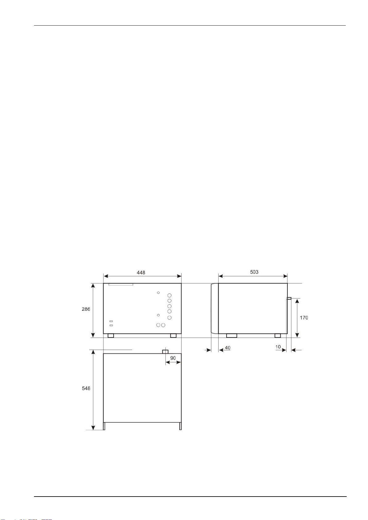
CNI 503A12S2
- 3x690V 50/60 Hz
- 8 kV Surge
- IEC & ANSI-B Kopplung manuell wählbar
Dimension: 19“, 9 HU
500 mm x 448 mm x 420 mm (LxBxH)
Weight: 48.9 kg
CNI 503 A14.1
- 3x440 V 50/60 Hz
- 8k V Surge
Dimension: 19“, 34 HU Rack
Weight: 181 kg (Rack with CNI 503A14.1 no generators)
EM TEST CNI 501 / CNI 503
Manual of operation V 3.32 15 / 41
4.4.
General
DC supply as per tables in 4.2
Coupling modes Surge IEC 61000-4-5
Line to Ground all combinations coupling capacitor 9F Source impedance 12
Line to Line all combinations coupling capacitor 18F Source impedance 2
Output sockets for testing signal and data lines with CNV 504 and CNV 508
Coupling modes Burst IEC 61000-4-4
Line(s) to ground all combinations
Output sockets for capacitive coupling clamp
Remote control
UCS 500; all models Burst and Surge
EFT 500, all models Burst
VCS 500M; all models Surge
Note: In case that all remote control input at the CNI 503 are available and the user has all above
mentioned generators available a simultaneous use of all generators is not allowed.
The operator has to decide either to use the UCS 500 or the EFT/VCS combination of generators.
Power supply
Mains 115 V / 230 V
Fuse 2 A slow blow all models
Dimension and weight
Housing 19” 6HU (models up to 32 A all models if not otherwise specified)
Weight 16 A models 3-ph: Approx. 30 kg
32 A models 3-ph: Approx. 45 kg models 1-ph approx. 30 kg
EM TEST CNI 501 / CNI 503
Manual of operation V 3.32 16 / 41
4.5.
Test level with Burst as per IEC 61000-4-4 Ed.2.
Burst generators, which comply with the specifications of IEC 61000-4-4 Ed2: 2004, have a limitation of the
maximum output voltage. Then the maximum test level is limited by the number of coupling on several lines.
Please see the following limits:
Coupling
UCS 500 >Vers.3.0
UCS 500M4 >Vers.3.0
UCS 500N4
EFT 500 /
EFT 500 M4
EFT 500N5
UCS 500N5
UCS500M7
UCS 500M6B
UCS500N6
UCS 500M6 >Vers.3.0
UCS 500M6A >Vers.3.0
EFT 500N8
EFT 500 M8
50
4800V
4800V
5500V
7000V
1 coupling any
4800V
4800V
5500V
7000V
2 couplings any
4800V
4800V
5000V
7000V
3 couplings any
4800V
4800V
5000V
7000V
Generator with
CNI 503 / CNE 503
CNI 501
UCS 500 >Vers.3.0
UCS 500M4 >Vers.3.0
UCS 500N4
EFT 500 /
EFT 500 M4
UCS500N5
EFT 500N5
UCS 500N5
UCS500M7
UCS 500M6B
UCS500N6
UCS 500M6 >Vers.3.0
UCS 500M6A >Vers.3.0
EFT 500 M8
50
4800V
4800V
5500V
5500V
1 coupling any
4800V
4800V
5500V
5500V
2 couplings any
4000V
4000V
5000V
5000V
3 couplings any
4000V
4000V
5000V
5000V
4 couplings any
4000V
4000V
4500V
4500V
5 couplings any
4000V
4000V
4500V
4500V
4.6.
Decoupling inductors for surge pulse
To prevent unwanted voltage drops in the coupling/decoupling networks, the value of the decoupling element
generally must be reduced for coupling/decoupling networks rated at >25 A. The Table below shows the reduced
inductor values per line in function of the rated current.
Rated current
Inductance per line
16 A
1.5 mH
32 A
0.75mH
63 A
0.6mH
100 A
0.6mH
200 A
0.3mH
For this case, the “time to half value” of the open-circuit voltage waveform may be reduced in accordance with
Tables 6 and 7 in standard IEC 61000-4-5.
EM TEST CNI 501 / CNI 503
Manual of operation V 3.32 17 / 41
5.
Operation
5.1.
Power supply input (EUT)
The power supply input for the EUT is located at the rear side of the coupler. Adapters for customized three phase
connectors have to be realized by the user himself or can be manufactured on customer’s specification.
The output of the power mains supply (surged lines) for the EUT is located at the front panel of the equipment.
5.2.
Synchronization
The transients generally must be related to a certain phase angle of the power supply. This is required for the surge
test and optional for the burst test.
The synchronization is normally realized within the VCS, the EFT and the UCS generator and is related to the power
supply input at the rear of the equipment, to phase L or the “Sync” input at the rear panel of the generator.
Then when using external 3ph couplers the generator itself has no power mains supply connected to the input for the
EUT supply at the rear panel.
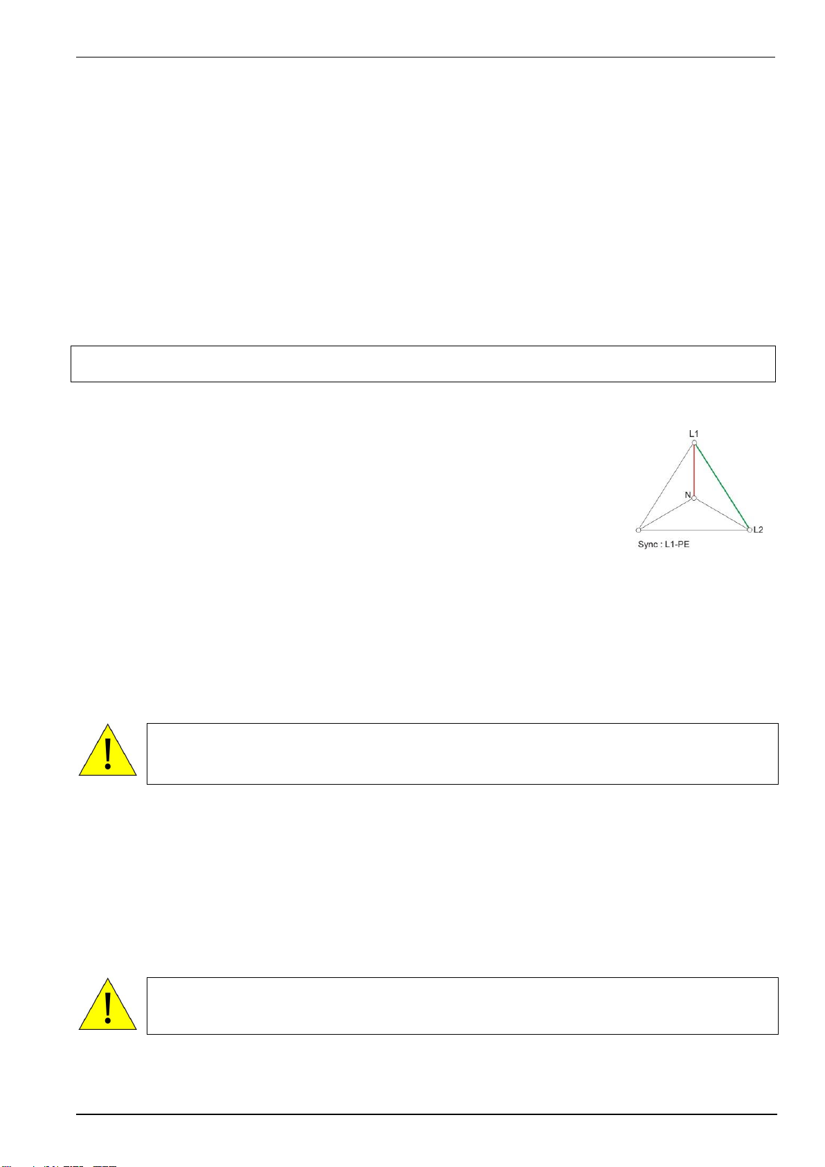
NOTE: The hardware is designed to synchronize the connected reference phase L to PE.
Phase synchronization angle in star-delta 3-phase system
The Generator synchronizes between the connected Phase Lx to PE. In a 3-phase system
the PE and Neutral are connected together at the supplier’s transformer. The pulse
generator is designed for a 3-phase system in star mode (L1, L2, L3, N, PE).
Then the synchronization in a 3-phase system is perfect for a 3-phase equipment with star
connection. For 3-phase equipment with delta connection the shift the phase angle for
triggering must be adjusted. The graphic in Figure 5.1 shows the different phase angle
between connection L1-N (star-) and L1-L2 (delta mode).
The generator manual describes the method of the phase angle setting of the generator.
Figure 5.1 Phase shift
between star and delta
Using a UCS 500N type
The synchronization is realized within the UCS generator and is related to the sync input at the rear of the UCS 500...
Then when using three phase couplers the UCS has no power at the sync input
Connect sync input of the UCS 500 to the phase L1 of the coupling network with. The UCS synchronizes to
this phase L1.
The sync input of the UCS 500 is referenced to ground (PE). The phase synchronization depends from
the Firmware version and is different.
Important information to the synchronization you can find into the UCS manual
Using a VCS 500 or EFT 500
The synchronization is realized within the VCS 500 or EFT 500 / 800 generators and is related to the power supply
input at the rear of the equipment, to phase L input.
Then when use three phase couplers, the generators have no power supply at the input for the EUT.
Connect phase L1 and neutral N of the power supply input of the coupling network with phase L and
neutral N at the input of the VCS, or EFT. The generator is synchronized to the phase connected at the
input L. Dependant on which phase, L1, L2 or L3 is connected to the generators; the transients are
synchronized to this line.
Connecting two devices VCS 500 and EFT 500 series on CNI network
In case that a Surge generator (VCS 500 series) and a Burst generator (EFT 500 series) are connected
simultaneously, both generators must be switched on. Otherwise the coupling modes might be set false.

EM TEST CNI 501 / CNI 503
Manual of operation V 3.32 18 / 41
5.3.
Connection of DC Equipment
For the connection of DC power supplies following connections are provided.
Polarity
3- Phase CNI
1- Phase CNI
+ Pole
L1
L
- Pole
N
N
As DC input the terminals L1 and N must be used. These two plugs are marked at the rear side of with an
additional plus or minus sign.
TEST ON Switch
The switching capacity of conventional AC contactors for DC application is limited. Therefore, the specification for
DC current and voltage are reduced compared to the AC specifications.
If the coupling network should have the same parameters for AC and DC, special mains switch must be installed,
for meet the DC specifications. This costly expansion requires a larger enclosure than the normal version.
Cost- economical coupling networks have no internal DC switches. In this case the user has already installed an
external dc switch, he can use for disconnect the dc supply in case of an emergency.
Coupling networks that require mandatory external DC contactor
The table on the right shows the coupling networks
that require an external power switch mandatory for
DC application.
Type
DC Parameter
CNI 503B7.4
CNI 503B9.2
1000V 32A
1000V 100A

EM TEST CNI 501 / CNI 503
Manual of operation V 3.32 19 / 41
5.4.
Operation with CNI coupler or generator internal CDN
The coupling network CNI 503 is operated via the generator UCS / VCS / EFT and its operation panel or via ISM
windows software. Only the different coupling modes can be changed or preselected.
Then it is very important that the control cable between surge generator and coupler, EFT generator and
coupler or UCS and coupler is connected and that the coupler is switched on (power switch at the rear
panel) before the test generators are switched on.
The test generator realizes that a three phase coupler is connected and shows the possible coupling modes in the
display of the generator. The complete system is controlled by the generators operation panel.
If the external coupling network is connected or switched on later than the generator, the generator must be reset by
switching power ON/OFF.
On the front panel of the coupler the user can switch ON/OFF the power supply of the EUT.
Using IEC.control software the coupling matrix is completely controlled by software.
CNI detection
After power ON the UCS / VCS or EFT generator, the devices check if an external CNI is
detected.
CNI detected: Working with external CNI
CNI not detected: Working with internal generator CDN
When changing between internal CDN to external CNI it is necessary to switch OFF/ON the system. When
CNI is not used switch off the CNI before power on the USC500N5
EM TEST CNI 501 / CNI 503
Manual of operation V 3.32 20 / 41
6.
Test set up
When setting up the test national and international regulations regarding human safety have to be guaranteed.
All units, the surge generator, the EFT and the coupling matrix can be installed one
above the other. The coupling matrix should than be used as central output for the
EUT and should be mounted directly onto the ground reference plane. The EFT
has to be installed directly over the coupling matrix to have the output connection
EFT - CNI as short as possible.
The surge generator VCS can be mounted besides or onto the other units. The UCS has
to be mounted directly above the CNI due to the short HV cable.
It is recommended to connect the simulator to the ground reference plane of the test
set-up.
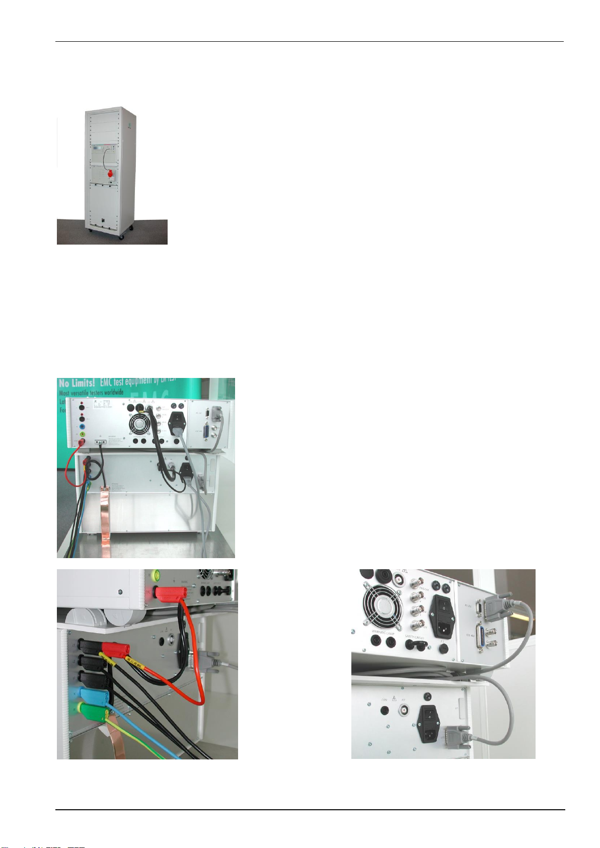
Figure 6.1: Example of a test rack with UCS 500M6 and CNI 503
Connect the following cables between the generator and coupling network
- Control cable UCS - CNI (15 pole SubD connector
- Control cable EFT - CNI (15 pole SubD connector)
Control cable VCS - CNI (15 pole SubD connector)
- High voltage cable, UCV / VCS - CNI (rear panel)
- High voltage common UCS / VCS - CNI (rear panel)
- High voltage cable, coaxial EFT - CNI (front panel)
(Black safety laboratory cable)
Additionally the coupling network needs a power mains supplyof 115V /230V at the rear.
Connection of CNI / CNV 503:
1. Connect the earth connection from UCS 500 to the CNI 503 with
the delivered brass connector plate (fig 6.7.) or the two parallel
cables (fig 6.6). This reference ground and must be connected
with the reference ground of the test set-up.
2. Connect the HV and COM connectors for transmit the surge
pulses to the CNI 503.
3. Connect DUT power supply L1 to the AC synchronization of the
UCS 500
4. CN cable for control the couplings from the impulse generator. For
reduce the interference’s we propose to roll up the cable and put it
between the UCS500 and the CNI 503
Figure 6.2: Connections UCS 500 –CNI 503
Figure 6.3 : Connection line power and sync to UCS 500
Figure 6.4 : Connection the CN cable
This manual suits for next models
56
Table of contents
Other EMTEST Test Equipment manuals

EMTEST
EMTEST dito User manual

EMTEST
EMTEST variac-NX 1-260-16 User manual

EMTEST
EMTEST CNI 508 N2 User manual

EMTEST
EMTEST esd NX30 User manual

EMTEST
EMTEST AN 200 Series Instruction Manual

EMTEST
EMTEST PFM 200N200 User manual

EMTEST
EMTEST VDS 200Q10 Series User manual

EMTEST
EMTEST PFM 200N100.1 User manual

EMTEST
EMTEST CWS 500A / 75 User manual

EMTEST
EMTEST PFS 200N Series Instruction Manual


