Paul FOCUS 200 Base User guide

Translation of the original instruction manual
Heat Recovery Unit
FOCUS 200 Base

Legal regulations
All rights reserved.
This instruction manual has been compiled with the utmost care. Nevertheless, the publisher accepts no liability for
damage caused by missing or incorrect details in this instruction manual. We reserve the right at any time and
without previous notification to change the content of this manual in part or as a whole.
The information contained in these documents is the property of Zehnder Group. Any form of publication, whether in
whole or in part, requires the written approval of Zehnder Group. In-house duplication, designated for the evaluation
of the product or for proper use, is permitted and not subject to approval.
Trademarks
All trademarks are recognised, even if they are not separately labelled. A missing label does not mean that an article
or sign is free of trademark rights.
© 2022 Zehnder Group

3
Contents
1Introduction ........................................................................................................................................... 5
General ................................................................................................................................................... 5
Validity .................................................................................................................................................... 5
Target groups.......................................................................................................................................... 5
Qualification of target group.................................................................................................................... 5
1.3.1.1 Users....................................................................................................................................................... 5
1.3.1.2 Qualified personnel ................................................................................................................................. 5
Conformity............................................................................................................................................... 5
2Proper use ............................................................................................................................................. 6
Operation of the unit................................................................................................................................ 6
Intended use ........................................................................................................................................... 6
Provisions for operation with fireplaces................................................................................................... 6
Guarantee conditions, warranty and liability............................................................................................ 6
Guarantee conditions.............................................................................................................................. 6
Warranty ................................................................................................................................................. 6
Liability.................................................................................................................................................... 7
3Safety ..................................................................................................................................................... 7
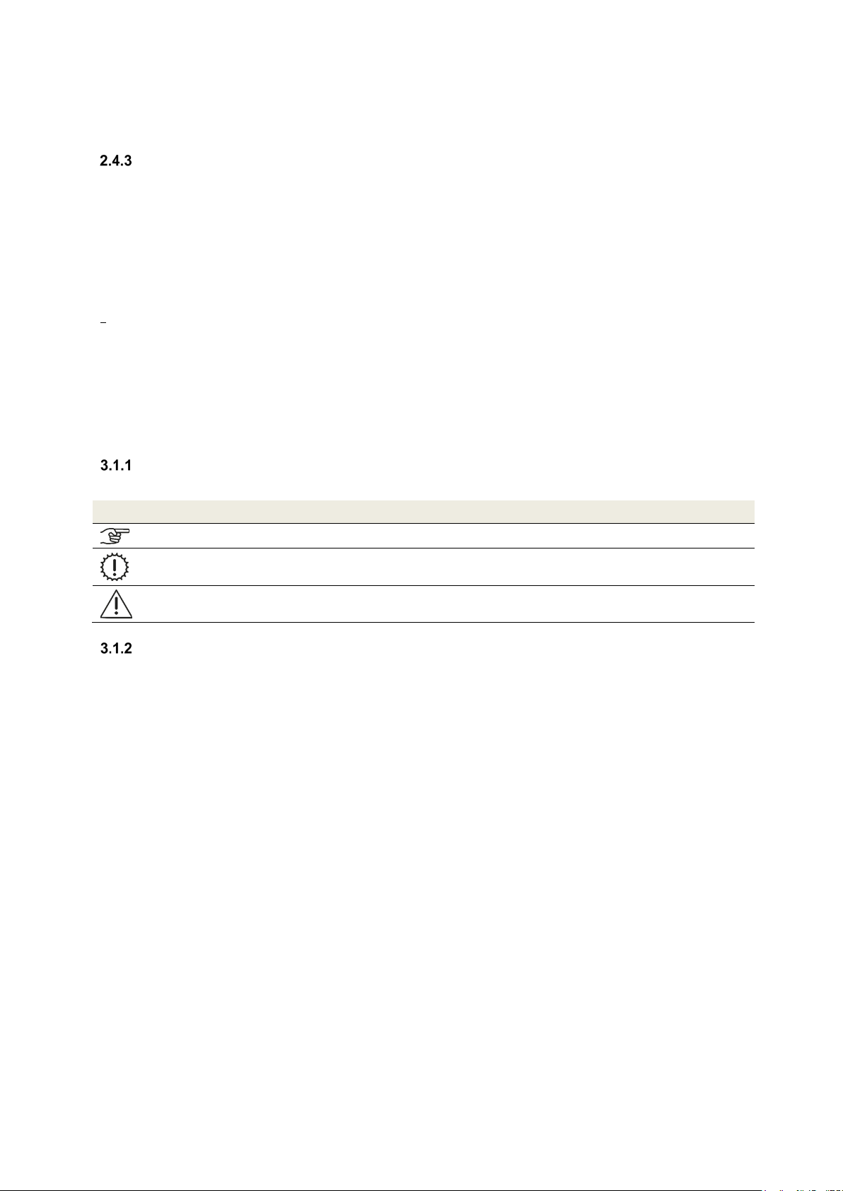
Symbols used ......................................................................................................................................... 7
Safety regulations ................................................................................................................................... 7
3.1.2.1 Safety instructions – general................................................................................................................... 7
3.1.2.2 Safety instructions – Installation.............................................................................................................. 8
Installation conditions.............................................................................................................................. 8
4Chapter for operators and qualified personnel .................................................................................. 8
Product description ................................................................................................................................. 8
Control panel........................................................................................................................................... 9
Main components.................................................................................................................................... 9
Type label ............................................................................................................................................... 9
Frost protection ....................................................................................................................................... 9
Available control modules ..................................................................................................................... 10
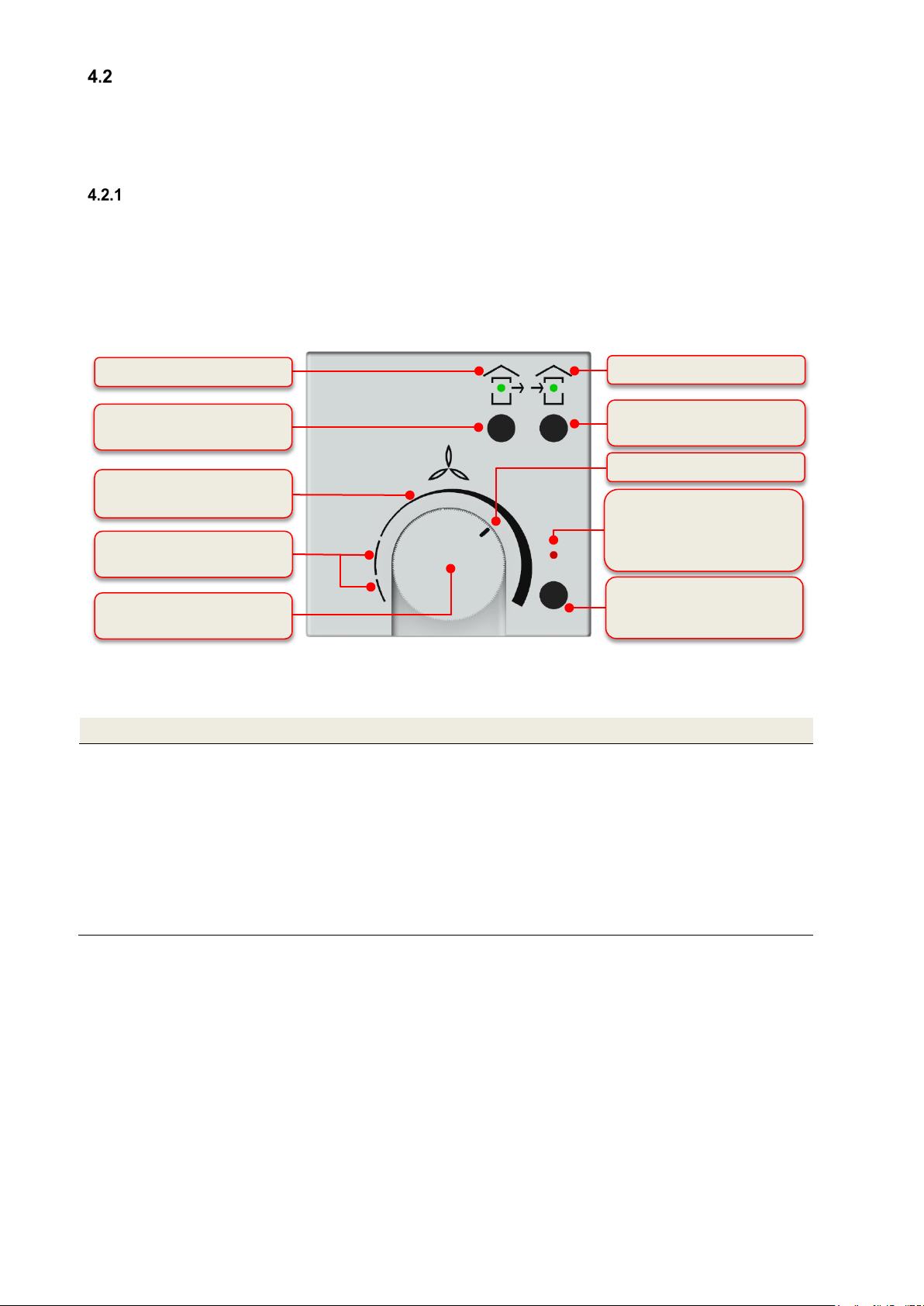
External control panel ........................................................................................................................... 10
4.2.1.1 Control panel operating functions ......................................................................................................... 10
4.2.1.2 Signals used to indicate working/maintenance conditions .................................................................... 11
External control signal 0–10 V .............................................................................................................. 11
Boost ventilation mode with external boost ventilation key ................................................................... 12
Maintenance by the user....................................................................................................................... 12
Replacing the unit filters........................................................................................................................ 12
Resetting the filter running time ............................................................................................................ 15
What should I do in case of a fault?...................................................................................................... 15
Disposal ................................................................................................................................................ 15
5Chapter for qualified persons ............................................................................................................ 15
Installation requirements....................................................................................................................... 15
Transport and packaging ...................................................................................................................... 15
Checking the scope of delivery ............................................................................................................. 15
Mounting ............................................................................................................................................... 16
Wall mounting ....................................................................................................................................... 16
Fitting on Floor stand (optional) ............................................................................................................ 17
Connecting the ventilation tubes........................................................................................................... 19
Connecting the condensate drain hose................................................................................................. 20
Electrical connections ........................................................................................................................... 21
Connecting the control panel ................................................................................................................ 22
5.3.1.1 Connecting the connecting cable to the flat connector plug.................................................................. 22
5.3.1.2 Connecting the connecting cable to the control panel........................................................................... 22
Connecting external boost ventilation keys........................................................................................... 23
Connecting external sensors................................................................................................................. 23
Connecting an external pre-heater........................................................................................................ 23
Commissioning ..................................................................................................................................... 24
Readiness for operation........................................................................................................................ 24
Adjusting the air volume flow ................................................................................................................ 24
Adjusting the valves .............................................................................................................................. 24
Service and maintenance...................................................................................................................... 25
Inspection and cleaning of the heat exchanger..................................................................................... 25

4
Swapping the heat exchanger for the summer box............................................................................... 28
Display of working conditions on the control board............................................................................... 28
Technical description............................................................................................................................ 28
Air connection design versions ............................................................................................................. 28
Technical specification.......................................................................................................................... 28
Dimensions........................................................................................................................................... 30
FOCUS 200 Base terminal scheme...................................................................................................... 31
6Appendices ......................................................................................................................................... 32
Checklist A Maintenance work for users............................................................................................... 32
Checklist B Maintenance work for qualified personnel.......................................................................... 33
Commissioning and handover protocol................................................................................................. 34
Air volume protocol............................................................................................................................... 35

5
1 Introduction
General
This translation of the original instruction manual contains instructions and information on the safe operation, correct
installation, operation and maintenance of the Focus 200 Base ventilation unit.
Subject to change and all rights reserved.
This documentation has been compiled with the utmost care. However, no rights can be derived from this regarding
the publisher’s liability for damages due to missing or incorrect information in this documentation. As a result, it is
possible that the unit may deviate slightly from this description. In the event of disputes, the German version of the
documentation shall be binding.
•Read the instructions in full before installing and commissioning the ventilation unit. This will help you avoid
hazards and errors.
•Be sure to observe all safety notes, warnings and information on precautionary measures.
•The instruction manual constitutes a part of the product. Keep the manual for future reference.
Questions
You can address all questions and request the most recent manuals and new filters from your Zehnder
representative. The contact information is found on the back cover of this manual.
Validity
This document applies to the following unit types:
•FOCUS 200 Base series (Zehnder Focus 200 Base series)
All the units in the FOCUS 200 series are referred to below using the generic product name FOCUS, except where it
is necessary to distinguish between specific types.
This instruction manual deals with the various design variants of the FOCUS heat recovery unit. Possible accessories
are only described to the extent necessary for appropriate operation of the unit. Please refer to the respective
instructions for further information on accessory parts.
Target groups
This instruction manual is for users and qualified personnel. The activities are only allowed to be carried out by
appropriately trained personnel who are sufficiently qualified for the respective work involved.
Qualification of target group
1.3.1.1 Users
Users must be instructed by qualified personnel as follows:
•Instruction in hazards when handling electrical devices
•Instruction in the operation of the FOCUS unit
•Instruction in the maintenance of the FOCUS unit
•Knowledge of and compliance with this manual, including all safety instructions
1.3.1.2 Qualified personnel
Qualified personnel must have the following qualifications:
•Training in dealing with hazards and risks when installing and operating electrical devices
•Training for the installation and commissioning of electrical devices.
•Knowledge of and compliance with the locally applicable building, safety and installation regulations of the
relevant local authorities or municipalities, the regulations of the water and electric utilities and other official
regulations and guidelines
•Knowledge of and compliance with this document, including all safety instructions
Conformity
The Focus 200 Base series ventilation units from the manufacturer
Zehnder Group Zwolle B.V.
Lingenstraat 2 ● 8028 ● PM Zwolle-NL ● Tel.: +31 (0)38-4296911
Zwolle commercial register 05022293
comply with the directives and standards of the EU Declaration of Conformity.

6
2 Proper use
Operation of the unit
The unit may only be operated if it has been installed correctly and according to the
specifications and directives of the installation manual of the unit.
The unit may be operated by the following groups of people: children from age 8,
persons with limited physical, sensory or mental abilities, or persons with insufficient
experience and specialised knowledge, provided they are supervised or instructed in
the safe handling of the unit and understand the associated hazards.
Children must not play with the unit.
Children must not carry out cleaning and maintenance without supervision.
Intended use
The FOCUS unit can be used for controlled ventilation in homes and offices (and
also in industrial buildings subject to certain restrictions). Any other use or any use
beyond this is considered improper use.
The ventilation unit is not suitable for smoke extraction or drying buildings, for
ventilation of rooms with aggressive and corrosive gases or for rooms with extreme
dust levels.
The unit must not be used for extracting combustible or explosive gases.
Intended use also includes observing all instructions in the instruction manual.
In the event of improper use, the Zehnder Group accepts no liability for any damage that may occur and no warranty
for the proper and functional operation of the ventilation unit.
Provisions for operation with fireplaces
Local requirements must be taken into account through appropriate standards, laws and guidelines. The FOCUS unit
may only be installed in rooms, apartments or utilisation units of comparable size in which open flue fireplaces are
installed if:
•safety features prevent simultaneous operation of open flue fireplaces and the air extracting system or
•the flue gas discharge of the open flue fireplace is monitored by special safety features. In case of open flue
fireplaces for liquid or gaseous fuels, the fireplace or the ventilation system must be switched off if the safety
feature is triggered. In case of open flue fireplaces for solid fuels, the ventilation system must be switched off if the
safety feature is triggered.
The ventilation units for controlled ventilation of an apartment or comparable utilisation unit must not be installed if
open flue fireplaces are connected to multiple-occupancy flue systems in the utilisation unit.
For proper operation, it must be possible to shut off any combustion ventilation lines and flue gas systems of open
flue fireplaces. In case of flue gas systems of fireplaces for solid fuels, it must only be possible to operate the cut-off
device manually. The position of the cut-off device must be recognisable from the setting of the operating handle.
This is considered to be fulfilled if a cut-off device against soot (soot blocker) is used. Fire protection requirements
with regard to the fire protection installation regulations for the construction of the ventilation system, and federal
state regulations, in particular the building authority guideline on the fire protection requirements for ventilation
systems in the currently valid version, must be observed.
Guarantee conditions, warranty and liability
Guarantee conditions
The manufacturer gives a warranty of 24 months starting from the installation date, or a maximum 30 months starting
from the date of manufacture, for the unit. Warranty claims may only be asserted for material defects and/or design
faults that have occurred during the warranty period.
In the event of a warranty claim, the unit must not be disassembled without the written consent of the manufacturer.
Spare parts are only covered by the warranty if they have been supplied by the manufacturer and fitted by an
approved technician.
Warranty
In the event of a warranty claim, the unit must not be disassembled without the written consent of the manufacturer.
Spare parts are only covered by the warranty if they have been supplied by the manufacturer and fitted by an
approved technician.
The warranty shall be null and void if:
•The warranty period has elapsed.
•The installation has not been carried out in accordance with the applicable regulations.

7
•The unit is operated without a filter.
•Original parts have been replaced by non-original parts.
•Unauthorised changes or modifications to the unit have been made.
•The defects are due to improper installation, improper use or neglected maintenance of the system.
Liability
The FOCUS unit is intended for use in the mechanical ventilation of apartments, offices and rooms with a similar
purpose. Every other use other than that described in chapter 2 is considered “improper use” and may result in
personal injury or damage to the balanced ventilation unit for which the manufacturer cannot be held liable.
The liability of the manufacturer becomes null and void in the following cases:
•Failure to observe the instructions specified in this manual pertaining to safety, operation and maintenance.
•Modifications to the ventilation unit or the use of components that have not been approved or recommended by
the manufacturer.
•Incorrect installation, improper use or contamination of the system.
•Original parts have been replaced by non-original parts.
•The unit is operated without a filter.
3 Safety
Carefully read all safety instructions prior to commissioning the unit to make sure that you use the unit in a safe and
intended way.
Symbols used
You will find the following symbols in this document:
Symbol Meaning
Important note!
Caution: Risk of affecting the operation of the ventilation system or damaging the unit!
Caution: Risk of personal injury!
Safety regulations
3.1.2.1 Safety instructions – general
Always observe the safety regulations, warning, comments and instructions stated in
this manual. Non-observance results in hazard of injury and hazard of material
damage to the FOCUS unit.
The installation, commissioning and maintenance (except for filter replacement) must
be carried out by an approved technician unless stated otherwise in the instructions.
Implementation of this work by a non-approved technician can result in personal
damage or reduced performance capacity of the ventilation system.
Do not disconnect the unit from the power supply unless instructions to the contrary
are listed in the manual. This can result in the formation of moisture and mould.
Do not make any changes to the unit or to the specifications listed in this document.
Such changes can cause personal injury or lead to reduced performance of the
ventilation system.
To prevent accidents, a damaged mains cable must be replaced by an original cable
by the manufacturer, a person commissioned to carry out maintenance by the
manufacturer or a similarly qualified person.
After installation, have your system engineer/installer instruct you on the unit and the
control panel. The ventilation unit may only be used in accordance with chapter 2
"Intended Use".
Only operate the unit with a closed housing.

8
3.1.2.2 Safety instructions – Installation
Comply with the general locally applicable building, fire, safety and installation
regulations of the relevant local authorities, the regulations of the water and electric
utilities and all other official regulations.
Pull the unit’s plug from the mains socket to separate the unit from the power supply.
If the unit does not have a plug, use a switch according to EN 60335-1 (with
separation of all three poles and 3 mm clearance, over-voltage category III).
Always disconnect the unit from the power supply prior to commencing maintenance
or repair activities. If the unit is operated while open, there is hazard of injury.
Make sure that the FOCUS unit cannot switch on unintentionally.
To eliminate the risk of coming into contact with the running fans, the air ducts must
be fastened to the unit before the power supply is connected, observing a minimum
length of 900 mm.
Therefore, always apply measures to prevent electrostatic discharges when working
on the electronics. Wear an antistatic wrist band, for example. Static energy can
cause damage to electronic components.
The entire installation must comply with the applicable (safety) regulations from the
following sources:
- local EU standard for safety features for low voltage systems;
- Mounting/installation manual of the manufacturer (see the back cover of the
instruction manual for the contact data of Zehnder).
A socket with grounding at a distance of 1 meter or no more than the length of the
included mains cable must be present.
For safety reasons do not use an extension cable.
Installation conditions
The following conditions must be considered when deciding whether a unit should be installed in a specific area to
ensure the correct installation of the unit.
•Ensure that the temperatures in the installation area are in the permissible range year-round. The information
regarding the permissible temperature can be found in the “Technical specification” table.
•When choosing an installation location, it is recommended that you avoid areas with a high average level of
humidity (ambient conditions for indoor climate control system must not continuously exceed 70% RH at 22 °C).
•The unit must not be installed in rooms subject to explosion hazards.
•Inside wet rooms, the unit may only be installed outside of protection zones 1 and 2 in accordance with DIN
57100/VDE 100 Part 701.
•Connect the unit to a power source with 230 V/50 Hz.
•Check whether the electrical installation is suitable for the maximum output of the unit. The values for the
electrical input power can be found in the “Technical specification” chapter.
•Check that the installation area of the unit meets the requirements in the “Installation requirements” chapter.
4 Chapter for operators and qualified personnel
Product description
The FOCUS unit is a ventilation unit with heat recovery for healthy, well-balanced and energy-saving comfort
ventilation. A comfort ventilation system extracts foul-smelling waste air from areas such as kitchens, bathrooms and
toilets and conveys an identical quantity of fresh air into living rooms, bedrooms and children's rooms. A highly
efficient cross-counterflow heat exchanger made from plastic is used for waste heat recovery. An optional summer
box module can be used instead of the heat exchanger for thermal separation of the two airflows. The housing is
made from sheet metal with an anthracite powder coating. The high-quality polypropylene inner lining ensures the
necessary thermal insulation and unit soundproofing.
The FOCUS unit has two maintenance-free 230 VAC centrifugal fans with an integrated power supply unit and
electronic commutation. The fans run at a steady volume flow to keep the air volume constant at any selected fan
speed. The air volume is not affected even if the filters become soiled.
The unit contains filters according to EN ISO 16890 of the filter class ISO Coarse for the outdoor air and the extract
air. These consist of a synthetic non-woven filter medium with a polypropylene frame. As an option, filters of filter
class ePM1 can be used for the outdoor air. The filters are accessed via the front panel.

9
Control panel
The external control panel allows you to operate the system from a central location. The control panel is only
suitable for use in indoor areas.
Main components
Fig. 1: Main components of the FOCUS ventilation unit
Item Description
A
Fastening sheet
B
Control cover plate
C
Control board
D
Filter (2x ISO coarse)
E
Summer box (optional)– Module that keeps the air flows thermally separate
F
Housing made from coated sheet steel
G
EPP moulded parts
H
Condensate drain screw connection
I
Fans (2x)
J
EPP foam cover for fan (2x)
K
Heat exchanger with strap and condensate tray
L
EPP foam cover with strap for filter and heat exchanger
M
Front panel made from coated sheet steel
Table 1: FOCUS main components
Type label
The type label identifies the product unequivocally. You will need the details on the type label for the safe use of the
product and in case of questions for service. The type label is located on the same side of the unit as the air
connections and must remain permanently attached to the product.
Frost protection
The FOCUS unit is equipped with automatic frost protection, which prevents the heat exchanger from freezing should
the outdoor air temperature drop to a very low level. The temperature limit for the outdoor air on the unit side is -3 °C.
If the temperature drops below this limit value, the fans are switched off temporarily, unless effective external frost
protection is in place in the system. If an external electric pre-heater (optional) is installed, it is activated by the unit
control system if the temperature drops below the limit value of 0 °C. The only electric pre-heater that may be used
for this purpose is the Iso defroster heater DN125 (Zehnder art. no 527003450).
If an optional hydraulic heating register is installed downstream, please note that the supply air
temperature is not monitored to protect it against freezing!
F
I
J
K
M
H
G
L
C
B
A
D
E

10
Available control modules
The FOCUS unit can be operated with the following control modules:
•External control panel (W x H x D in mm: 71 x 71 x 25)
•External control signal (0–10 V)
•External boost ventilation key(s) (as many as required, potential-free)
External control panel
To control the fans, the control panel has a rotary knob with an infinitely variable adjustment range (first scaling
segment on the intensity scale) for the air volume flow.
The two ON/OFF keys can be used to set the operating mode. You can choose between normal mode (both fans
switched on), extract air mode (only the exhaust air fan switched on) or supply air mode (only the supply fan switched
on). The green LED above the respective symbol indicates which mode has been set. Use the boost ventilation
mode/reset filter running time key to trigger the operating function associated with each one. The operating LED
lights up red to indicate that the un-occupied or boost ventilation operating modes are possibly active or that the
filters should be inspected.
4.2.1.1 Control panel operating functions
Description Explanation
Intensity scale
Rotary knob
positioning
Operating mode:
Ventilation with constant air volume flow
according to the intensity
scale
Position 1st scaling segment on the left: lowest air volume flow
Position 1st scaling segment on the far right: highest air volume flow
Positions within the 1st scaling segment: air volume flow proportional to the intensity
scale
Un-occupied mode: Ventilation with the lowest intermittent air volume flow
Position 2nd scaling segment: 5 minutes ON and 1 minute OFF
Position 3rd scaling segment on the far left: 1 min ON and 5 min OFF
Positions within 2nd and 3rd scaling segment: ON/OFF cycle-time ratio adapted indirectly
proportional
Fig. 2: Operation and information fields control panel
Function LED red
un-occupied mode/boost ventilation
mode/filter control
Filter control
ON/OFF touch keys
Supply air mode
Intensity scale operating mode
1st scaling segment
ON/OFF touch keys
Extract air mode
Rotary knob for adjusting the air
volume flow
Functional key
Boost ventilation mode/reset filter
running time
Extract air symbol with green LED
Supply air symbol with green LED
Current position of rotary knob
Intensity scale for un-occupied
mode 2nd and 3rd scaling segment

11
Touch key
Extract air mode
Pressing this key so that it clicks into place activates extract air mode and switches on
the exhaust air fan. Pressing it again deactivates extract air mode.
If the ventilation unit is being operated together with a
fireplace, do not use this touch key unless supply air mode
is activated at the same time! Simultaneous operation of a
ventilation system and fi
replace imposes more stringent safety
requirements with regard to low pressure monitoring and a switch-
off function is required for the ventilation unit.
Touch key
Supply air mode
Pressing this key so that it clicks into place activates the supply air mode and switches
on the supply air fan. Pressing it again deactivates the supply air mode.
Normal mode
Pressing both keys so that they click into place switches on both fans.
Key
Boost ventilation
mode/reset filter
running time
Function key for boost ventilation mode:
Pressing this key activates boost ventilation for 15 minutes with an air volume flow
corresponding to the rotary knob being turned all the way to the right. At the end of the
15-minute boost ventilation time, the unit reverts to the previous air volume in the
currently active mode. You can cancel the boost ventilation mode at any time by
pressing this key again for > 3 s.
Function key for reset filter running time:
To ensure cyclic filter inspection, the control has an integrated operating hours counter
with a fixed running time of 180 d. The boost ventilation mode/reset filter running time
key allows you to reset the filter running time. To restart the filter running time, press
and hold this key for > 3 s.
If the filter running time is reset before the end of 180 d by pressing this key for > 3 s,
the LED fan symbol will blink rapidly four times in succession to confirm the reset
operation.
No reset command can be issued while boost ventilation mode is active!
Table 2: External control panel operating functions
4.2.1.2 Signals used to indicate working/maintenance conditions
Symbol LED signal Function / Meaning / Action required
Both LEDs light up
Normal mode (extract air and supply air)
Extract air symbol
LED lights up
Extract air mode is active (extract air only)
Supply air symbol
LED lights up
Supply air mode is active (supply air only)
Fan symbol
LED lights up
Ventilation boost mode is active
The boost ventilation mode can be selected while in
any other mode!
Fan symbol
LED blinks
Un-occupied mode is active
Un-occupied mode can be selected while in any
other mode!
Fan symbol
LED blinks rapidly Filter running time has expired; inspect or replace filter
Boost ventilation mode cannot be activated until a
reset command is issued!
Table 3: Functions assigned to LED signals
External control signal 0–10 V
The ventilation unit can be operated with an external 0–10 V control signal. When a 0–10 V analogue signal is
applied, it is interpreted as a control signal for the fan speed. The current position of the rotary knob on the scale
marks the point at which the external control voltage becomes effective.
To make use of the entire external 0–10 V control range, the rotary knob must be pointing to the
position of the 3rd scaling segment!

12
Boost ventilation mode with external boost ventilation key
Boost ventilation keys are usually installed in rooms from which air is extracted, such as bathrooms, toilets or
kitchens. In this way, maximum ventilation can be activated locally within these rooms for a specific period to enable
rapid extraction of high humidity and odours. When this control module is activated, the functional features and
displays described for boost ventilation mode apply. Boost ventilation mode is restarted each time it is activated and
interrupts the currently set air volume flow. Afterwards, the unit reverts to the previously active working condition.
Maintenance by the user
For the user, maintenance of the ventilation unit and system is limited to replacing the filters periodically and cleaning
the supply and extract air valves. The filters should be inspected every three months. Filter replacement should be
carried out as necessary, but no later than once every six months. As part of this process, please inspect the other
filters in the ventilation system and replace them if necessary. The filter mats on the extract air valves (e.g. bathroom,
kitchen, WC) should be replaced or cleaned every 2–3 months or when checking the degree of contamination at
one's own discretion.
If the maintenance work is not carried out regularly, this will affect the functionality of the comfort
ventilation system in the long run!
Replacing the unit filters
The system must not be operated without filters. During filter replacement and maintenance work,
the ventilation unit must remain switched off!
Two high-quality original filters from the manufacturer are installed in the FOCUS unit. The filters must be inspected
whenever the control panel signals that this is necessary. In doing so, proceed as follows:
1. Disconnect the unit from the mains power supply.
2. Press the two snap fasteners Aon the bottom of the unit.
Fig. 3: Pressing the snap fasteners
3. Remove the front panel Bgradually as indicated by the arrows. To do this, open the front panel in the snap
fastener area at an angle of no more than 15° and unhook it from the lock seam of the housing.
A

13
Fig. 4: Opening the front panel
4. Use strap Cto pull the EPP foam cover Dfor the filters and heat exchanger out of the EPP housing. To do
this, grip the strap at one end and pull while using your other hand to support the unit.
Fig. 5: Pulling out the EPP foam cover of the filters and heat exchanger
5. Holding them by the strap, pull the filters Eout of the filter compartments.
D
C
B

14
Fig. 6: Pulling out the filters
6. On the filter frame of each filter, there is an arrow to indicate the prescribed direction of flow. Insert the new
filters according to their designated direction of flow F.
Fig. 7: Inserting the new filters according to the direction of flow
Depending on the unit type according to the type label, filters with filter class ISO ePM1 must
be inserted into the filter compartment of the outdoor air connector! The outdoor air
connector is indicated by the symbol
on the air connections sticker.
7. Attach the EPP foam cover to enclose the slide-in filter compartments and heat exchanger.
8. Hook the front panel into the lock seam of the housing. Then press it down onto the housing in the snap
fastener area until it engages in the snap fasteners.
9. Reconnect the unit to the mains.
F
E

15
Resetting the filter running time
After completing the filter replacement, the counter for the filter running time must be reset. To reset the filter running
time, press and hold the boost ventilation mode/reset filter running time key for > 3 s. The LED on the fan symbol
stops blinking rapidly.
Use check list A to document the maintenance work completed.
What should I do in case of a fault?
Contact the installation technician in case of a fault. Note down the type of your FOCUS unit according to the type
label on the side of the unit where the air connections are located.
The mains connection must always be established, unless the FOCUS unit has to be shut down due to a serious
fault, for maintenance work or for some other urgent reason.
As soon as the unit is disconnected from the mains, the apartment will no longer be mechanically
ventilated. This may result in moisture and mould problems in the apartment. Therefore, you should
avoid switching off the FOCUS unit for long periods.
Disposal
The unit must be disposed of in an environmentally-friendly manner. Do not dispose the unit with your domestic
waste.
Packaging materials, consumables and waste equipment must be disposed of at the end of their
useful life in accordance with the applicable regulations in your country.
5 Chapter for qualified persons
Installation requirements
The following requirements must be assured for the correct installation:
•Installation in accordance with the general and locally applicable safety and installation regulations, such as the
electric and water utilities etc. and in accordance with the regulations stipulated in this instruction manual
•Frost-free indoor area
•Power supply 230 VAC, 50 Hz
•Sufficient space for connecting the ventilation tubes and for maintenance work
Transport and packaging
Proceed with care when transporting and unpacking the FOCUS unit.
Do not remove the unit packaging until right before installation! Before and during interruptions to
the installation, the ventilation tube connections must be closed with the air connector sealing caps
to prevent construction site dust and moisture from entering.
Checking the scope of delivery
If the delivered product is found to be damaged or incomplete, please contact the supplier immediately. Included in
the scope of delivery are:
•Ventilation unit FOCUS with power cable,
Check the type label to make sure that the unit is the right one (type, version as per type label)
•Fastening sheet with two self-adhesive spacers (rubber buffers)
•Control panel
•Instruction manual
•Product labels showing energy efficiency

16
Mounting
The distances from adjacent surfaces shown in Fig. 8 must be observed. Please note that these are not shown to
scale. The surfaces are allowed to be made from flammable materials:
Fig. 8: Distances from adjacent surfaces in mm
Make sure you leave at least 1 m clearance in front of the FOCUS unit for subsequent maintenance
work.
The FOCUS unit must be installed horizontally. Before mounting the unit on a wall, check that the wall construction
has the necessary load-bearing capacity (net weight of the FOCUS unit is 25 kg) and that the fastening sheet can be
mounted securely. In case of unsuitable walls, we recommend using the floor stand for fitting to the floor (optionally
available). This prevents potential transfer of structure-borne noise as much as possible.
Wall mounting
Proceed as follows for wall mounting:
1. Mount the supplied fastening sheet Ahorizontally on the wall with the lugs Bpointing upwards. Use the slotted
holes Cto fix it in place with suitable fixing materials.
Fig. 9: Fastening sheet for wall mounting
A
B
C

17
Observe the minimum distance required in relation to the finished floor!
Fig. 10: FFL distance for wall mounting (version LEFT)
2. Stick one of the supplied self-adhesive spacers Din each corner on the rear of the unit.
Fig. 11: Spacers mounting
3. Hook the FOCUS unit onto the fastening sheet by inserting the lugs Binto the slots Ein the lock seam at the
top of the rear cover.
Fig. 12: Hooking the unit into the fastening sheet
Fitting on Floor stand (optional)
The dimensions of the floor stand are as follows: footprint = (620 x 292) mm; variable height adjustment = between
280 mm and 320 mm using adjustable feet. The floor stand consists of two long base parts (each with two adjustable
feet) and two short base parts.
D
E
B

18
Fig. 13: Individual parts of the floor stand
Assemble the individual parts of the floor stand as shown in the illustrations. In doing so, proceed as follows:
1. Working in the direction of the arrow, place the short base part at right angles to the long base part at a
staggered height.
Fig. 14: Assembling the base parts
2. Working in the direction of the arrow, push the lugs Aof the short base part into the guide slots Bof the long
base part so that they engage and fix the two base parts together.
Fig. 15: Fixing the two base parts
3. Now connect the other two base parts in the same way.
A
B

19
F
Fig. 16: Two sets of base parts fixed together
4. Mount the fastening sheet Con the long base part with the lugs pointing upwards. To do this, screw the two
Parker screws Dinto the holes provided Eon the base part so that they go through the fastening sheet.
Fig. 17: Mounting the fastening sheet on the base part
5. Now use the height-adjustable feet Fto adjust the fully assembled floor stand on the designated set-up area
so that it is plumb vertical and stable. Then fix it in this height position with the lock nuts of the adjustable feet.
Fig. 18: Aligning the floor stand
6. Place the FOCUS unit on the floor stand so that the lugs of the fastening sheet hook into the slots in the lock
seam at the bottom of the unit's rear cover. See Fig. 12.
Connecting the ventilation tubes
The following points must be observed when installing the ventilation tubes:
•Attach the different types of ventilation tube provided with the ventilation system to the relevant connectors
according to whether the unit is the LEFT- or RIGHT-hand version (see air connections sticker on control
cover plate).
C
E
D

20
•Remove the sealing caps from the air connectors.
•Using ventilation tube materials with the lowest possible air resistance, connect the ventilation technology
components to one another so that they are air-tight.
•The unit connectors are made from EPP and have a sleeve size of DN 125.
•The outdoor air and exhaust air tubes must be insulated in such a way that they are sealed against vapour
diffusion. This prevents condensate from forming on the outside of the ventilation tubes.
•If – when installing the exhaust air tube – it is not possible to avoid a low point between the exhaust air
connector on the unit and the exhaust air outlet, a connection to the condensate drain must be provided at this
point. This is because the exhaust air is saturated with steam at cold outdoor temperatures and droplets may
be deposited on the inner wall of the tube.
•The exhaust air pipework that runs from the unit connector to the roof terminal must not be straight.
Otherwise, any ice that forms could drop onto the blades of the exhaust air fan when it thaws, causing
damage to the blades.
Fig. 20: Drainage arrangement for outdoor and exhaust air tubes
•If an attenuator is fitted at the exhaust air connector, it must be routed upwards with a bend to prevent it being
drenched by condensate running back from the exhaust air tube.
•If the exhaust air is routed above the roof, a double-walled or insulated roof passage must be installed. This
prevents condensate from forming between the roof boards.
•For the supply and extract air ducts, we recommend using thermal and vapour-tight insulation to prevent
unnecessary temperature losses in both the summer and winter.
Connecting the condensate drain hose
In the heat exchanger, the warm extract air is cooled by the outdoor air. This causes the moisture in the room air to
condense inside the heat exchanger. The condensate that forms in the heat exchanger is routed to the sink valve.
The sink valve screw connection Ahas a 1¼" male thread for the siphon. This is located on the bottom of the FOCUS
unit, with the exact position varying according to the unit version and design.
Fig. 19: Arrangement of the air connections Unit version LEFT and unit version RIGHT
Outdoor air
Exhaust air
Exhaust air
Outdoor air
Other manuals for FOCUS 200 Base
2
Table of contents
Other Paul Heating System manuals
Popular Heating System manuals by other brands

Uponor
Uponor Smatrix Base PULSE quick guide

Envirovent
Envirovent heatSava installation guide

Vaillant
Vaillant ecoTEC plus SERIES Setup instructions

BriskHeat
BriskHeat Custom Series instruction manual

Daikin
Daikin VRV III REYQ8PY1B Service manual

Stuart Turner
Stuart Turner BEP 130 Installation, Operatation & Maintenance Instructions