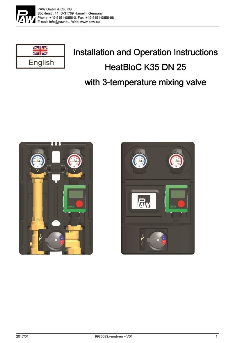
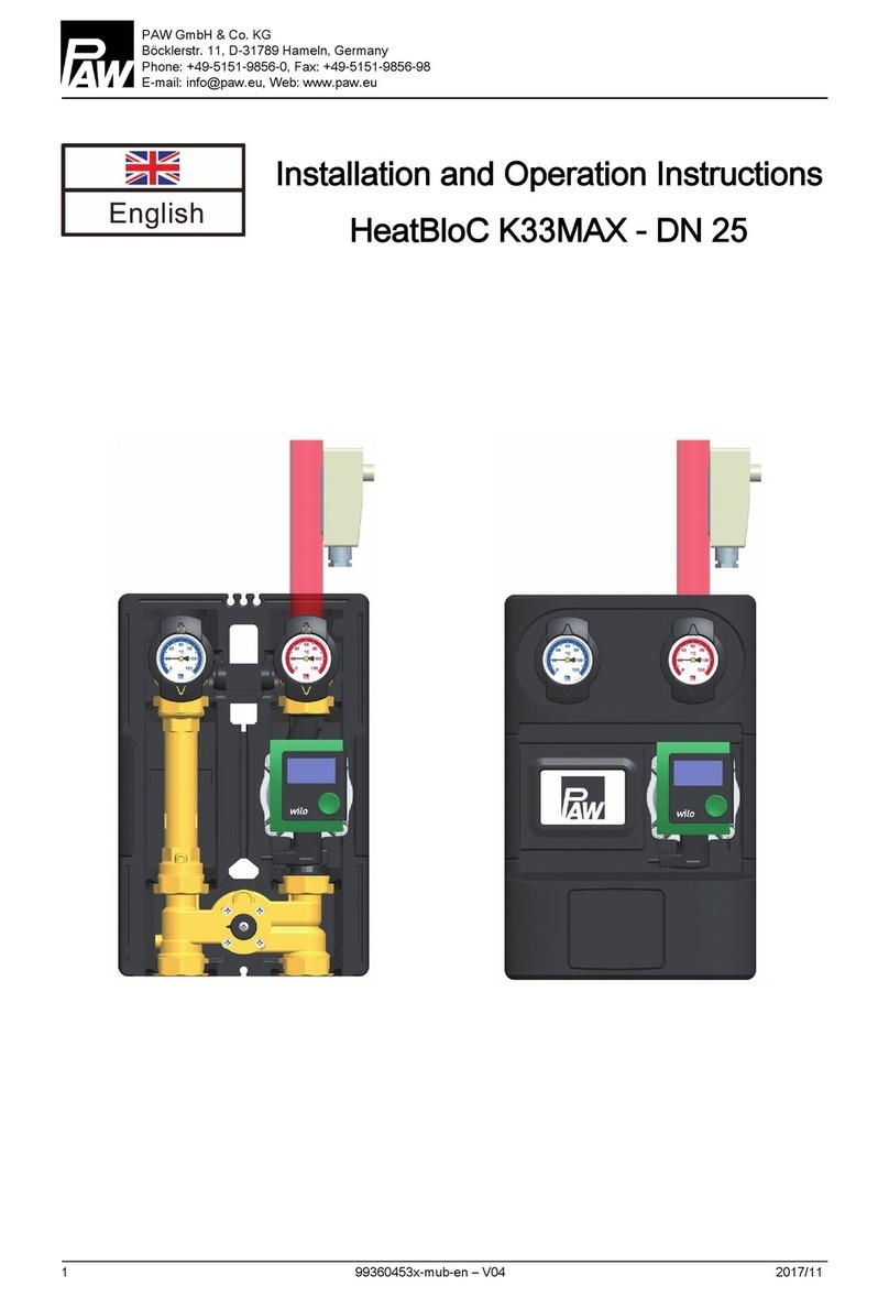
PAW K32-3/4 User manual

PAW NA Limited Partnership
45 Davis Street, Webster, Ma 01520, USA
phone: +1-508-943-4240, fax: +1-508-943-4141
email: supp[email protected], web: www.paw.eu
Installation and O
Installation and OInstallation and O
Installation and Operation
peration peration
peration I
II
Instr
nstrnstr
nstructions
uctionsuctions
uctions
Zone M
Zone MZone M
Zone Module K32
odule K32odule K32
odule K32
-
--
-
¾
¾¾
¾" (
" (" (
" (DN
DN DN
DN 2
22
20
00
0)
))
)

1 For your safety
2 9932053WI21NA – V02 2012/02
Contents
1
11
1
For your safety
For your safetyFor your safety
For your safety
................................
................................................................
................................................................
................................................................
................................................................
................................................................
................................................................
................................................................
...............................................
..............................
...............
3
33
3
1.1
About this manual ............................................................................................................................................... 3
1.2
Designated use ................................................................................................................................................... 3
1.3
Qualification of the installer ................................................................................................................................. 4
1.4
Hand-over of the system [Specialist] ................................................................................................................... 4
1.5
General safety instructions .................................................................................................................................. 5
2
22
2
Product description and functions
Product description and functionsProduct description and functions
Product description and functions
................................
................................................................
................................................................
................................................................
................................................................
................................................................
...................................................
......................................
...................
6
66
6
2.1
Flow check valve [Specialist] .............................................................................................................................. 7
2.2
3-way mixing valve [Specialist] ........................................................................................................................... 8
3
33
3
Mo
MoMo
Mounting and installation [Specialist]
unting and installation [Specialist]unting and installation [Specialist]
unting and installation [Specialist]
................................
................................................................
................................................................
................................................................
................................................................
................................................................
.............................................
..........................
.............11
1111
11
3.1
Mounting of the modular distribution manifold/fastening bracket with mounting plate [Specialist] .................... 11
3.2
Mounting the zone module [Specialist] .............................................................................................................. 12
3.3
Start-up [Specialist] ........................................................................................................................................... 14
4
44
4
Cleaning
CleaningCleaning
Cleaning
................................
................................................................
................................................................
................................................................
................................................................
................................................................
................................................................
................................................................
.......................................................
..............................................
.......................14
1414
14
5
55
5
Maintenance and decommissioning [Specialist]
Maintenance and decommissioning [Specialist]Maintenance and decommissioning [Specialist]
Maintenance and decommissioning [Specialist]
................................
................................................................
................................................................
................................................................
.............................................................
..........................................................
.............................15
1515
15
5.1
Pump [Specialist] .............................................................................................................................................. 15
6
66
6
Spare parts
Spare partsSpare parts
Spare parts
................................
................................................................
................................................................
................................................................
................................................................
................................................................
................................................................
................................................................
...................................................
......................................
...................16
1616
16
7
77
7
Technical data and pressure drop characteristics
Technical data and pressure drop characteristicsTechnical data and pressure drop characteristics
Technical data and pressure drop characteristics
................................
................................................................
................................................................
................................................................
...........................................................
......................................................
...........................17
1717
17
7.1
Pressure drop characteristic ............................................................................................................................. 18
Item no. 9932053WI21NA – Version V02 – Issued 2012/02
We reserve the right to make technical changes without notice!
Printed in Germany – Copyright by PAW NA Limited Partnership
PAW NA Limited Partnership
45 Davis Street
Webster, Ma 01570, USA

1 For your safety
2012/02 9932053WI21NA – V02
3
1
11
1For your safety
For your safetyFor your safety
For your safety
Carefully read this manual before installation
and start-up. Non-observance of the
instructions in this manual may lead to material
damage and serious injuries that may result in
death.
Keep this manual in close proximity of the
system for later use.
indicates the risk of death,
serious injuries or
considerable material
damage in case the
corresponding precautions
are not observed.
indicates the risk of light
injuries in case the
corresponding precautions
are not observed.
indicates the risk of material
damage in case the
corresponding precautions
are not observed.
1.1
1.11.1
1.1 About this manual
About this manualAbout this manual
About this manual
This manual describes the functions,
installation, start-up and operation of the mixed
zone module K32 for heating zones controlled
by a mixing valve. The chapters called
[Specialist] are only referred to specialists.
For other components of the heating system,
such as boiler, storage tanks, pressure relief
valves and controllers, refer to the instructions
of the corresponding manufacturer.
1.2
1.21.2
1.2 Designated use
Designated useDesignated use
Designated use
The zone module may only be used in closed hydronic
heating systems. The zone module may not
notnot
not be used in
potable water applications or for process water. The
technical limit values specified in this manual must be
adhered to.
Unintended use of the zone module will invalidate any
liability claims.
Only use PAW accessories for the zone module.
The wrapping materials are made of recyclable materials
that can be recycled by standard recycling operations.

1 For your safety
4 9932053WI21NA – V02 2012/02
1.3
1.31.3
1.3 Qualification of the installer
Qualification of the installerQualification of the installer
Qualification of the installer
Installation and commissioning of this equipment should
be done by qualified installers [Specialist] in accordance
with local, state and federal codes which may be
applicable.
The following must also be observed during installation
and commissioning:
•Relevant regional and national regulations (for
example Occupational Safety and Health Act)
•Relevant accident prevention regulations (for
example of the Employer's Liability Insurance
Association)
•Instructions and safety instructions mentioned in
this manual
1.4
1.41.4
1.4 Hand
HandHand
Hand-
--
-over of the system
over of the systemover of the system
over of the system
[Specialist]
[Specialist][Specialist]
[Specialist]
After installation and start-up, the installer is responsible
for familiarizing the end user with the functions of the
system and the basic safety measures.
Hand the manual over to the end user. Instruct
the end user to keep the manual in close
proximity to the system.
Instruct the end user to have the zone module
serviced and repaired by a specialist only. The
zone module does not contain any parts which
may be repaired by the end user.
Explain to the end user the functions of the
system and the safety devices. Point out to the
end user that the shell must remain mounted
during operation and that the ball valves must be
open.

1 For your safety
2012/02 9932053WI21NA – V02
5
1.5
1.51.5
1.5 General
General General
General safety
safetysafety
safety
instructions
instructionsinstructions
instructions
Before installing and putting the product into operation, you must read and observe the following safety instructions:
Risk of burns!
Risk of burns!Risk of burns!
Risk of burns!
The valves, fittings and the pump may heat up to more than 212 °F (100 °C) during
operation.
The shell must remain closed during operation.
Personal injury and material damage!
Personal injury and material damage!Personal injury and material damage!
Personal injury and material damage!
The zone module is only suitable for use in heating circuits filled with heating water with
neutral pH.
The zone module may not
notnot
not be used in sanitary water applications.
Flush the heating circuit before installation to remove scale residues.
Material damage due to mineral oils!
Material damage due to mineral oils!Material damage due to mineral oils!
Material damage due to mineral oils!
Mineral oil products permanently damage the EDPM sealing elements, resulting in a loss
of their sealing characteristics. We cannot be held liable for damage caused by seals
thus damaged, nor will we offer a replacement under warranty.
It is imperative to prevent the EPDM sealing elements from making contact with
substances containing mineral oils.
Use silicone- or polyalkylene-based lubricants free of mineral oil, such as Unisilikon
L250L and Syntheso Glep 1 from the company Klüber or a silicone spray.

2 Product description and functions
6 9932053WI21NA – V02 2012/02
2
22
2Product description and functions
Product description and functionsProduct description and functions
Product description and functions
K32
K32 K32
K32 –
––
–
zone module
zone modulezone module
zone module
with 3
with 3with 3
with 3-
--
-way mixing valve
way mixing valveway mixing valve
way mixing valve
The integrated mixing valve controls the supply temperature
of the heating circuit. Hot generation water is mixed with
cooled return water to generate the desired constant supply
temperature of the heating circuit. The mixing valve is
adjusted by means of an external controller in combination
with an electric actuator.
Fields of application:
Fields of application:Fields of application:
Fields of application:
•Systems with several heating circuits and various
supply temperatures (radiator and radiant floor
heating)
•Systems with high fluctuations in supply temperature
depending on the generator (solid fuel boiler,
systems with combined heat and power)
A-1 Supply (consumer circuit)
A-2 All-metal temperature gauge integrated in the
ball valve with immersion sleeve (supply)
B Heating pump
C 3-way mixing valve
C-1 Supply (heat generator)
C-2 Return (heat generator)
D-1 Flow check valve, can be opened
D Return pipe
E Design insulation with optimized function
F-2 All-metal temperature gauge integrated in the
ball valve with immersion sleeve (return)
F-1 Return (consumer circuit)

2 Product description and functions
2012/02 9932053WI21NA – V02
7
2.1
2.12.1
2.1 Flow check valve [Specialist]
Flow check valve [Specialist]Flow check valve [Specialist]
Flow check valve [Specialist]
The zone module is equipped with an openable flow check valve (D-1) that is integrated in the return pipe.
Operation
OperationOperation
Operation
During operation, the marking must point to "Z".
The flow check valve is closed.
Flow only in the direction of the arrow.
Filling
FillingFilling
Filling,
, ,
, draining, ventilating
draining, ventilatingdraining, ventilating
draining, ventilating
For filling, draining and ventilating, the marking must point to "A".
The flow check valve is opened.
Flow in both directions.

2 Product description and functions
8 9932053WI21NA – V02 2012/02
2.2
2.22.2
2.2 3
33
3-
--
-way mixing valve
way mixing valveway mixing valve
way mixing valve
[S
[S[S
[Specialist]
pecialist]pecialist]
pecialist]
The motor-powered 3-way mixing valve (C) controls the supply temperature of the consumer circuit to the required value
by means of a supply sensor and a controller.
Position 10: passage position, no admixture
Supply temperature of the consumer = supply temperature of the heat generator
Position 0: 100% admixture
Supply temperature = return temperature of the consumer

2 Product description and functions
2012/02 9932053WI21NA – V02
9
Changing the supply line
Changing the supply lineChanging the supply line
Changing the supply line
[Specialist]
[Specialist][Specialist]
[Specialist]
Dismounting the mixing valve
Dismounting the mixing valveDismounting the mixing valve
Dismounting the mixing valve
1. Remove the temperature gauge handles (A-2, F-2) and withdraw the front shell.
2. Remove the fitting assembly from the rear shell.
3. Dismount the mixing valve (C).
Modifying the mixing valve
Modifying the mixing valveModifying the mixing valve
Modifying the mixing valve
1. Loosen the screw (1).
2. Remove the knob (2) from the plug axis.
3. Loosen the screws (3).
4. Remove the cover plate (4).
5. Loosen the two screws (5).
6. Remove the front plate (6).
7. Extract the sealing bush (7) with the cock plug (8) from the housing of the mixing valve.
8. Loosen the screws (10) on the rear side of the mixing valve.
9. Remove the cover (9) from the rear side of the mixing valve, place it on the other side of the mixing valve and fix
it by means of the screws (10).
10. Insert the sealing bush (7) with the cock plug (8) into the channel of the mixing valve.
11. Screw down the front plate (6) using the screws (5).

2 Product description and functions
10 9932053WI21NA – V02 2012/02
12. Turn the cover plate (4) such that the designation PAW is on the bottom and the scale is positioned according to
the figure above.
13. Screw down the cover plate (4) using the screws (3).
14. Put the knob (2) on the plug axis.
15. Screw down the knob (2) with the cock plug (8) using the screw (1).
Modifying and c
Modifying and cModifying and c
Modifying and commissioning the zone module
ommissioning the zone moduleommissioning the zone module
ommissioning the zone module
[Specialist]
[Specialist][Specialist]
[Specialist]
1. Swap the return pipe (D) and the supply length with the pump (B).
Observe the flow dir
Observe the flow dirObserve the flow dir
Observe the flow direction of the pump!
ection of the pump! ection of the pump!
ection of the pump!
Turn the pump head such that the terminal box points upwards or to the center of the fitting assembly.
2. Dismount and replace the ball valves.
3. Mount and connect the zone module.
4. Check all the union nuts and tighten them if necessary before commissioning.
5. Carry out a pressure test and mount the insulation.
Engage the temperature gauge handles (A-2, F-2).
Mixing valve with supply on the right Mixing valve with supply on the left
supply
supply

3 Mounting and installation [Specialist]
2012/02 9932053WI21NA – V02
11
3
33
3Mounting and installation [Specialist]
Mounting and installation [Specialist]Mounting and installation [Specialist]
Mounting and installation [Specialist]
Damage to property!
Damage to property!Damage to property!
Damage to property!
The zone module may only be installed indoors with a power supply of 120 V / 60 Hz.
The installation site must be dry, stable and frost-free.
3.1
3.13.1
3.1 Mounting of the modular distribution manifold/fastening bracket with mounting plate
Mounting of the modular distribution manifold/fastening bracket with mounting plateMounting of the modular distribution manifold/fastening bracket with mounting plate
Mounting of the modular distribution manifold/fastening bracket with mounting plate
[Specialist]
[Specialist][Specialist]
[Specialist]
The zone module must be mounted on a PAW modular
distribution manifold or on a fastening bracket set with
mounting plate. The modular distribution manifold, the
fastening bracket and the mounting plate are not
included in the scope of delivery.
Mount the modular distribution manifold or the fastening
bracket with mounting plate according to the description
in the separate manual.
If possible, select the fastening holes that are farthest
from the wall. It is then easier to mount the insulation.

3 Mounting and installation [Specialist]
12 9932053WI21NA – V02 2012/02
3.2
3.23.2
3.2 Mounting the zone module
Mounting the zone moduleMounting the zone module
Mounting the zone module
[Specialist]
[Specialist][Specialist]
[Specialist]
Risk of electric shock!
Risk of electric shock!Risk of electric shock!
Risk of electric shock!
Prior to commencing electrical work, pull the mains plug!
Only after completing all installation work, should the mains plug be plugged into a
socket! This avoids an unintentional start of the motors.
The zone module can be installed
•Option 1:
on a PAW modular distribution manifold.
•Option 2:
on a fastening bracket with mounting plate.
Supply
Supply
Heat generator
Supply
Supply
Return
Return
Return
Return
Heat generator
Consumer circuit Consumer circuit

3 Mounting and installation [Specialist]
2012/02 9932053WI21NA – V02
13
1. Remove the temperature gauge handles
(A-2, F-2) and withdraw the front shell of the
zone module.
2. Unscrew the nuts of the lower connections of the
zone module and remove the O-rings.
3. Put both nuts over the flanges.
4. Insert the gaskets in the nuts.
5. Place the zone module on both nuts.
6. Fully tighten the nuts.
Make sure that the nuts do not jam and that the
gaskets cannot slip.
7. Connect the zone module and the system by
means of pipes. Ensure stress-free mounting to
the pipeline.
8. Connect the pump.
9. Carry out a pressure test at operating pressure.
Check all screw connections and retighten them,
if necessary.
10. Mount the front shell and the temperature gauge
handles (A-2, F-2).
The assembly of the zone module is now completed and
you can put the system into operation.
Flange
(top view)
Nut
1
2
3
Flange
(side view)
gasket

4 Cleaning
14 9932053WI21NA – V02 2012/02
3.3
3.33.3
3.3 Start
StartStart
Start-
--
-up
upup
up
[Specialist]
[Specialist][Specialist]
[Specialist]
1. Open the ball valves by means of the
temperature gauge handles (A-2, F-2).
2. Fill the system with treated heating water.
3. Adjust the operating pressure.
Ball valve closed Ball valve open
4
44
4Cleaning
CleaningCleaning
Cleaning
Risk of burns!
Risk of burns!Risk of burns!
Risk of burns!
The valves, fittings and the pump may heat up to more than 212 °F (100 °C) during
operation.
The shell must remain closed when cleaning.
Clean the zone module from the outside with a damp cloth only. Never use scouring or sand-containing cleaning agents.

5 Maintenance and decommissioning [Specialist]
2012/02 9932053WI21NA – V02
15
5
55
5Maintenance and decommissioning [Specialist]
Maintenance and decommissioning [Specialist]Maintenance and decommissioning [Specialist]
Maintenance and decommissioning [Specialist]
Before maintaining and decommissioning the product, you must read and observe the following safety instructions:
Risk of electric shock!
Risk of electric shock!Risk of electric shock!
Risk of electric shock!
Disconnect all electrical devices in the heating circuit from the power supply before
carrying out maintenance work or decommissioning!
Secure the electrical devices against being switched on again.
Risk of burns an
Risk of burns anRisk of burns an
Risk of burns and scalding!
d scalding!d scalding!
d scalding!
Before starting maintenance work or decommissioning, switch off the heat generator.
Wait until the heating water has cooled down to 95 °F (35 °C).
1. Switch the heat generator off and wait until the
heating water has cooled down.
2. Disconnect the controller from the power supply.
3. Connect a hose to the pet cock of the heating
system.
4. Drain the cooled-down heating water into a
suitable container.
5. Dismount the zone module.
Now you can carry out the maintenance work or dispose of
the zone module by observing the local requirements.
5.1
5.15.1
5.1 Pump
PumpPump
Pump
[Specialist]
[Specialist][Specialist]
[Specialist]
The pump can be completely isolated. It can be replaced and maintained without draining the water of the heating circuit.
Isolating the pump
Isolating the pumpIsolating the pump
Isolating the pump
1. Close the ball valves in the supply and return line (A-2, F-2).
2. Remove the actuator from the mixing valve.
3. Turn the adjusting knob of the mixing valve such that the black nose points to "VL zu" (supply closed). Now the
mixing valve is drip-tight.

6 Spare parts
16 9932053WI21NA – V02 2012/02
6
66
6Spare parts
Spare partsSpare parts
Spare parts

7 Technical data and pressure drop characteristics
2012/02 9932053WI21NA – V02
17
7
77
7Technical data and pressure drop characteristics
Technical data and pressure drop characteristicsTechnical data and pressure drop characteristics
Technical data and pressure drop characteristics
K3
K3K3
K32
22
2
-
--
-
¾
¾¾
¾"
""
"
Dimensions
DimensionsDimensions
Dimensions
Center distance (1) ~3.54" (90 mm)
Width insulation (2) ~7.17" (182 mm)
Height insulation (3) ~15.1" (383 mm)
Mounting length (4) ~10.04" (255 mm)
Connections
ConnectionsConnections
Connections
Upper connections (A-1, F-1) ¾" female
Lower connections (C-1, C-2) 1" male
Technical Data
Technical DataTechnical Data
Technical Data
Maximum pressure 116 psi (8 bar)
Maximum temperature 230 °F (110 °C)
CV value 3.5
Opening pressure flow check valve (D-1) 7.9 inch head
Materials
MaterialsMaterials
Materials
Valves and fittings Brass
Gaskets EPDM / NBR
Insulation EPP

7 Technical data and pressure drop characteristics
18 9932053WI21NA – V02 2012/02
7.1
7.17.1
7.1 Pressure drop characteristic
Pressure drop characteristicPressure drop characteristic
Pressure drop characteristic
Flow rate [US gpm]
Pressure [m wc]
Pressure [ft head]
Flow rate [l/h]

Submittal Data Information
Submittal Data InformationSubmittal Data Information
Submittal Data Information
Low temperature zone module K32
Low temperature zone module K32Low temperature zone module K32
Low temperature zone module K32
¾
¾¾
¾
"
""
"
Version: 01 Effective: Feb. 21, 2012 Supersedes:
32053WI21
NA
Job:_____________________ Engineer:________________ Contractor:_______________ Rep:____________________
ITEM NO. MODEL NO.
Features:
Connections top: ¾" female
Connections bottom: 1" male
3-way mixing valve made of brass
PAW heating circulation pump
Pump can be shut off completely
Full port ball valves with large handle
All-metal temperature gauges integrated in
the ball valve with thermowell
Check valve in the return pipe, with manual
opener for faster line drain sevice, spring-
actuated, thus suited for vertical and flow-
down assembly, supply line can be
changed on site (standard = right)
All water-carrying parts made of brass
Fully assembled with flat gaskets
Design insulation with optimized function
made of durable elastic EPP
Low temperature zone module K32 is
replacing conventional injection mixing
systems. In conjunction with electronic
reset control and direct drive actuator, it
modulates a 3-way valve, diverts and
mixes radiant return water with hot water
from the boiler. The constant speed
circulator delivers the required water
temperature to the radiant loop manifolds.
The K32 can handle radiant load demands
of up to 72 kBTU/h.
Your current method of zoning the radiant
loops (manifolds, zone valves etc.) does
not change with the installation of the K32.
Multiple K32 modules can be used to
separate the distinctive temperature
requirements between manifolds. No
special piping, just 2 connections and your
installation is complete.
Dimensions
Dimensions
Dimensions
Dimensions
Nominal diameter ¾" / DN 20
Height insulation ~15.1" / 383 mm
Width insulation ~7.17" / 182 mm
Length ~10.04" / 255 mm
Centre distance ~3.54" / 90 mm
Upper pipe connections ¾" female
Lower pipe connections 1" male
Limits
Limits
Limits
Limits
Max. admissible pressure 116 psi / 8 bars
Max. operating temperature 230 °F / 110 °C
CV value 3.5
Application range at
ΔT = 36 °F
up to 72 kBTU/h /
21 kW
Material
Material
Material
Material
Fittings Brass
Gaskets EPDM / NBR
Insulation EPP
PAW products specified in Imperial or metric units are approximate and are provided for reference only. For precise measurements, please contact PAW Technical Service. PAW
reserves the right to change or modify product design, construction, specifications, or materials without prior notice and without incurring any obligation to make such changes and
modifications on PAW products previously or subsequently sold.
In the USA distributed by PAW NA Limited Partnership, 45 Davis Street, Webster, MA 01570, Tel: +1-508-943-4240, Fax: +1-508-943-4141 - Visit our website at: www.paw.eu

7 Technical data and pressure drop characteristics
20 9932053WI21NA – V02 2012/02
Table of contents
Other PAW Control Unit manuals
Popular Control Unit manuals by other brands

Emerson
Emerson Keystone PED Operating and safety instructions

EisSound
EisSound 400 Series User and installation manual

National Instruments
National Instruments 9477 Operating instructions and specifications

Fortinet
Fortinet FIM-7920E Guide

NXP Semiconductors
NXP Semiconductors LPC55S6 Series Application note

Pickering
Pickering 40-519A user manual