PAW FriwaMidi-DN 20 User manual

PAW GmbH & Co. KG
Böcklerstr. 11, D-31789 Hameln, Germany
Phone: +49-5151-9856-0, Fax: +49-5151-9856-98
2016/07 99640x6xx-mub-de –V08 1
Installation and Operation Instructions
Domestic hot water modules
FriwaMidi –DN 20
FriwaMaxi –DN 25

1General Information
2 99640x6xx-mub-de –V08 2016/07
Contents
1General Information.........................................................................................................3
1.1 Scope of these instructions .......................................................................................... 3
1.2 About this product ........................................................................................................ 4
1.3 Designated use ............................................................................................................ 4
2Safety instructions ...........................................................................................................5
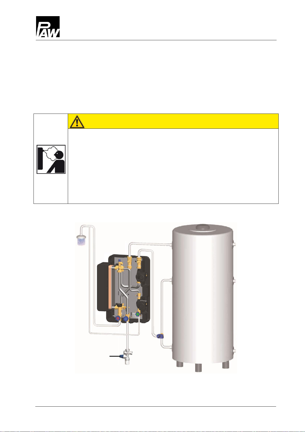
3Product description..........................................................................................................7
4Dimensioning and planning..............................................................................................8
4.1 Dimensioning of the tank.............................................................................................. 9
5Circulation mode ...........................................................................................................10
6Assembly and installation [specialist]..............................................................................11
7Commissioning [specialist].............................................................................................14
7.1 Filling the primary circuit............................................................................................. 15
7.2 Commissioning of the controller ................................................................................. 16
7.3 Maximum withdrawal flow rate ................................................................................... 18
7.4 Setting the temperature.............................................................................................. 20
8Maintenance [specialist].................................................................................................21
9Spare parts [specialist] ..................................................................................................22
9.1 Spare parts control and insulation FriwaMidi (6405640 / 6405641)
and FriwaMaxi (6406662 / 6406663).......................................................................... 22
9.2 Spare parts hydraulics FriwaMidi without circulation (6405640) /
with circulation (6405641) .......................................................................................... 23
9.3 Spare parts hydraulics FriwaMaxi without circulation (6406662) /
with circulation (6406663)............................................................................................ 24
10 Technical data...............................................................................................................25
10.1 Pressure drop characteristic curves FriwaMidi ........................................................... 26
10.2 Pressure drop characteristic curves FriwaMaxi .......................................................... 26
11 Commissioning report....................................................................................................27
Item no. 99640x6xx-mub-de - Version V08 –Date 2016/07
Translation of the original instructions
We reserve the right to make technical changes without notice!
Printed in Germany –Copyright by PAW GmbH & Co. KG
PAW GmbH & Co. KG
Böcklerstraße 11
D-31789 Hameln, Germany

1General Information
2016/07 99640x6xx-mub-de –V08 3
1General Information
1.1 Scope of these instructions
These instructions describe the installation, commissioning, function and operation
of the domestic hot water modules FriwaMidi and FriwaMaxi.
The chapters called [specialist] are intended for specialists only.
For other components of the system, such as tanks, controllers or pumps, please observe
the instructions of the corresponding manufacturer.
Item
Item
number
Controller
FC3.8
Pump
primary
Circulation
Heat exchanger
FriwaMidi
6405640
Grundfos
UPM2 25-75
Optional:
Grundfos
UPM2 15-75 CIL2
40 plates
6405641
Grundfos
UPM2 25-75
Grundfos
UPM2 15-75 CIL2
Item
Item
number
Controller
FC3.8
Pump
primary
Circulation
Heat exchanger
FriwaMaxi
6406662
Grundfos
UPML 25-105
Optional:
Grundfos
UPM2 15-75 CIL2
60 plates
6406663
Grundfos
UPML 25-105
Grundfos
UPM2 15-75 CIL2
Carefully read these instructions before installation and commissioning.
Save these instructions in the vicinity of the installation for future reference.

1General Information
4 99640x6xx-mub-de –V08 2016/07
1.2 About this product
The domestic hot water module is a premounted fitting group checked for leakage and
used to transfer the heat between the buffer tank and the domestic hot water circuit.
It contains a preset controller and important fittings for the operation of the system:
Ball valves in the primary circuit
Piston valves in the secondary circuit
Pressure relief valve in the secondary circuit
Premounted controller
Temperature sensor on the cold water inlet
Temperature sensors on the heating flow
Temperature sensor on the domestic hot water outlet
Flow meter on the domestic hot water outlet
Fill and drain valve for draining the heat exchanger
Vent plug for venting the heat exchanger
1.3 Designated use
The domestic hot water module must only be used in heating installations between
the buffer tank and the domestic hot water circuit.
Due to its design, the station must be mounted and operated in a vertical position!
The technical data specified in these instructions must be observed.
Only use PAW accessories with the domestic hot water module.
Improper usage excludes any liability claims.
The wrapping materials are made of recyclable materials and can be disposed of
with recyclable materials.

2Safety instructions
2016/07 99640x6xx-mub-de –V08 5
2Safety instructions
The installation and commissioning as well as the connection of electrical components require
technical knowledge commensurate with a recognised vocational qualification as a fitter for
plumbing, heating and air conditioning technology, or a profession requiring a comparable
level of knowledge [specialist].
The following must be observed during installation and commissioning:
relevant local and national regulations
accident prevention regulations of the professional association
instructions and safety instructions of this manual
WARNING
Danger of scalding due to hot water!
Undesirable circulation of water in the primary circuit can cause the exit of water
of up to 90 °C at the withdrawal point.
External pumps must not be installed between the domestic hot water
module and the buffer tank.
The domestic hot water module must not be connected to a distribution
manifold.
CAUTION
Risk of burns!
The valves, fittings and the pump may heat up to more than 95 °C
during operation.
The insulating shell must remain closed during operation.

2Safety instructions
6 99640x6xx-mub-de –V08 2016/07
NOTICE
Material damage due to mineral oils!
Mineral oil products cause lasting damage to seals made of EPDM, whereby the sealant
properties get lost. We do not assume liability nor provide warranty for damage to property
resulting from sealants damaged in this way.
It is imperative to avoid that EPDM gets in contact with substances containing
mineral oils.
Use a lubricant based on silicone or polyalkylene and free of mineral oils,
such as Unisilikon L250L and Syntheso Glep 1 of the Klüber company or a silicone
spray.
NOTICE
Malfunction!
The domestic hot water module must be integrated in the potential equalisation of
the electric installation. This can be guaranteed by establishing a potential equalisation
connection to the main potential connection according to regulations or by the connected
pipe system.

3Product description
2016/07 99640x6xx-mub-de –V08 7
3Product description
Example: FriwaMaxi with circulation
Connections
1
Primary side: return to the buffer tank
2
Secondary side:
hot water circulation, return
3
Secondary side: cold water inlet
4
Secondary side: hot water outlet
5
Primary side: flow from the buffer tank
Equipment
A
Ball valve with check valve
B
Primary pump
C
Non-return valve with drain valve
D
Circulation pump
E
Piston valve with drain valve
F
Piston valve with drain valve
G
Piston valve with drain valve
and temperature sensor
H
Fill and drain valve
and temperature sensor
I
Flow meter FlowSonic
J
Plate heat exchanger
K
Circulation line
L
Vent valve (primary circuit)
M
Temperature sensor and pressure relief
valve 10 bars, suitable for DHW
Only for the protection of the station.
Does not replace the pressure relief
valve that has to be mounted on site!
N
Ball valve with check valve

4Dimensioning and planning
8 99640x6xx-mub-de –V08 2016/07
4Dimensioning and planning
The FriwaMidi and FriwaMaxi are domestic hot water modules which heat potable
water operating on the principle of a flow-type water heater.
The FriwaMidi and FriwaMaxi can only work flawlessly if the installation meets certain
requirements. Please take some time to plan the installation.
WARNING
Danger of scalding due to hot water!
Undesirable circulation of water in the primary circuit can cause the exit of
water of up to 90 °C at the withdrawal point.
External pumps must not be installed between the domestic hot water
module and the buffer tank.
The domestic hot water module must not be connected to a distribution
manifold.
Mounting example
FriwaMidi with optional circulation set (item no. 640412) and with optional return distribution
(FriwaMidi: item no. 640423, FriwaMaxi: item no. 640424)
Safety group
according to DIN 1988

4Dimensioning and planning
2016/07 99640x6xx-mub-de –V08 9
4.1 Dimensioning of the tank
Thanks to the following table, you can calculate the approximately required volume of
the buffer tank.
Temperature in
the buffer tank
Domestic hot water
temperature set at
the controller
Required tank volume
per litre of hot water
50 °C
45 °C
1.3 litres
60 °C*
45 °C
0.8 litre
50 °C
1.0 litre
55 °C
1.4 litres
70 °C
45 °C
0.7 litre
50 °C
0.8 litre
55 °C
0,9 litre
80 °C
45 °C
0.5 litre
50 °C
0.6 litre
55 °C
0.7 litre
*Calculation example for the dimensioning of the buffer tank:
Temperature buffer tank: 60 °C
Maximum withdrawal quantity needed: 20 l/min
Domestic hot water temperature set at the controller: 45 °C
How large must the tank be to allow for a continuous withdrawal during 20 minutes
without reheating?
20 l/min x 20 min = 400 l
400 l x 0,8 = 320 l
The heated part of the buffer tank must have a volume of 320 litres.

5Circulation mode
10 99640x6xx-mub-de –V08 2016/07
5Circulation mode
The domestic hot water modules FriwaMidi and FriwaMaxi are optionally equipped with
a circulation pump.
The FriwaMidi and FriwaMaxi without circulation can be subsequently equipped with
a circulation set (item no. 640412).
Three different operating modes of the circulation pump are set at the controller
(see controller instructions, menu "Func" / "F02"):
Pulse-controlled operation (depending on the demand / requirements):
The short opening of a hot water tap (tap pulse: ~2 sec.) starts the circulation pump.
The circulation pump will then run for several minutes (adjustable).
Time-dependent operation:
The operation of the circulation pump can be set on a week clock within a freely
selectable period of time. The circulation will start at the beginning of the period
of time chosen. The circulation will stop after the end of the chosen period of time.
Temperature-dependent operation:
In this operating mode, the circulation only starts if the adjustable minimum temperature
on the circulation temperature sensor is not reached during the chosen period of
operation. The circulation stops after the required temperature has been reached
or after the end of the chosen period of time.
The operating modes can be combined with one another as wished, f. ex. the time- and the
temperature-dependent operating modes. The circulation is only active if the temperature at the
circulation temperature sensor falls below the required value and if the time window is active.
Outside the time window, the circulation pump can be started by a tap pulse if the
pulse-controlled operation mode is additionally activated.
NOTICE
Damage to property!
When the Friwa is delivered, the circulation is not activated (see controller instructions, menu:
"Func" / "F02" set to "OFF"). Once the circulation line mounted, it is mandatory to select and
preset the operating mode. The revolution speed of the circulation pump must be determined
by the PWM signal (factory setting: 40 %).

6Assembly and installation [specialist]
2016/07 99640x6xx-mub-de –V08 11
6Assembly and installation [specialist]
The domestic hot water modules FriwaMidi and FriwaMaxi must only be connected to the
storage tank by separate connections for the flow and return. External pumps must not be
installed between the domestic hot water module and the buffer tank. The circulation of
water causes considerable temperature fluctuations.
The domestic hot water connection must be carried out in accordance with the
relevant norms (for example DIN 1988)!
NOTICE
Damage to property!
The pressure relief valve integrated in the station does not replace the safety groups of the
potable water connection as per DIN 1988. The pressure relief valve only protects the module
from over pressures in case of servicing.
NOTICE
Damage to property!
If there are water supplies that may cause pressure surges (for example flush valves, washing
machines or dishwashers) connected to the same mains as the domestic hot water module, we
recommend the installation of water hammer arresters close to the place where these pressure
surges may be caused.
For example the make Flexofit S of the Flamco-Flexon company or the make reflex of
the Winkelmann + Pannhoff GmbH company.
Domestic
hot water
module
Fittings
Drain valve
Pressure relief valve
Return valve (non-return valve)
Evtl. pressure reducing valve
Test valve
Shut-off valve
Hot water
Cold water

6Assembly and installation [specialist]
12 99640x6xx-mub-de –V08 2016/07
WARNING
Risk to life and limb due to electric shock!
Prior to commencing electrical work on the controller, pull the mains plug!
Plug the mains plug of the controller into a socket only after completing all
installation work. Thus, an unintentional start of the motors is avoided.
NOTICE
Damage to property!
The location of installation must be dry, load-carrying, frost-proof and protected against
ultraviolet radiation, in order to prevent material damage of the installation.
1. Determine the mounting location of the domestic
hot water module near the buffer tank.
The pipes in the heating circuit must not exceed
a length of 4 m (for DN 32).
2. You can use a drilling template in order to facilitate
the installation. You will find the drilling template
on the station.
3. Copy the measures for the mounting holes
to the wall.
4. Drill the holes and insert adequate wall plugs
into the holes.
5. Turn the screws into the wall plugs, so that about
40 mm of each screw still stick out.
6. Remove the station from the packaging.
7. Remove the insulating front shell.
8. Hang the domestic hot water module onto the
screws. Tighten the screws, so that the sides
of the insulation are flush to the wall.

6Assembly and installation [specialist]
2016/07 99640x6xx-mub-de –V08 13
9. Use the piping to connect the domestic hot water
module to the installation according to the
adjacent figure.
1
Primary side:
return to the buffer tank,
connection FriwaMidi: 1½" ext. thread,
connection FriwaMaxi: 2" ext. thread,
Piping:
FriwaMidi: at least DN 25, 28 x 1,5 mm,
FriwaMaxi: at least DN 32, 35 x 1,5 mm,
maximum length 2 m
2
Secondary side:
hot water circulation, return,
connection: 1" ext. thread, flat sealing
3
Secondary side:
cold water inlet,
connection FriwaMidi: 1" ext. thread, flat sealing
connection FriwaMaxi: 1¼" ext. thread, flat sealing
4
Secondary side:
hot water outlet,
connection FriwaMidi: 1" ext. thread, flat sealing
connection FriwaMaxi: 1¼" ext. thread, flat sealing
5
Primary side:
flow from the buffer tank,
connection FriwaMidi: 1½" ext. thread,
connection FriwaMaxi: 2" ext. thread,
Piping:
FriwaMidi: at least DN 25, 28 x 1,5 mm,
FriwaMaxi: at least DN 32, 35 x 1,5 mm,
maximum length 2 m
Pipe distance to the wall
(primary) = 95 mm
Pipe distance to the wall
(secondary) = 167 mm

7Commissioning [specialist]
14 99640x6xx-mub-de –V08 2016/07
7Commissioning [specialist]
Note!
Slowly open the valves in the pipes and in the module, in order to prevent pressure surges.
Functioning check valve
The ball valves (A) and (N) in the primary circuit
are equipped with a check valve, in order to
avoid unwanted gravity circulation.
For venting and flushing the installation, the check
valves must be open. Turn the ball valves therefore
into the position 45°.
The check valve is not operating.
During operation, all the (ball) valves must
be completely open (position 0°).
Position 0°
Position 45°
Position 90°
Check valve is operating,
flow only in flow direction.
Check valve is not operating,
flow in both directions.
Ball valve closed,
no flow.
14

7Commissioning [specialist]
2016/07 99640x6xx-mub-de –V08 15
7.1 Filling the primary circuit
WARNING
Danger of scalding due to hot water!
The system is under pressure. By opening the vent valve, hot water
with a temperature of up to 90 °C may exit and cause personal injury.
Open the vent valve slowly and with sufficient distance.
If the storage tank is (partly) filled
1. Slowly open the ball valves (A) and (N) by turning
them into position 0°.
2. Fill the storage tank using the already existing
fill valves until an operating pressure of about
1.5 bars* is reached. Use appropriate water
according to VDI 2035 / ÖNorm H5195-1.
3. Manipulate the vent valve (L) cautiously
to let the air escape.
5. Close the vent valve (L).
6. Check the operating pressure of the storage
tank after venting and increase the pressure
if necessary.
7. Open the ball valves (A) and (N) completely
by turning them into position 0°.
Primary circuit
* 1.5 bars in the primary circuit = recommended minimum value
The pressure also depends on the individual system pressures and on
the components of the heating installation!

7Commissioning [specialist]
16 99640x6xx-mub-de –V08 2016/07
7.2 Commissioning of the controller
WARNING
Risk to life and limb due to electric shock!
Check if the sensors and the pumps are properly connected to
the controller and if the controller housing is closed.
Only under these circumstances, the mains plug of the controller
can be plugged into a socket.
1. Connect the domestic hot water module to the
mains (230 V, 50 Hz) using the premounted
connection cable.
2. Start the pump ("H1") in the main menu
of the controller in the manual mode
(PWM signal = 100 %),
see controller instructions page 19.
3. Let the pump run for several minutes
to vent the domestic hot water module.
4. If the air noises do not stop, carefully manipulate
the vent valve (L) while the pump is still running
and let the air escape.
5. If the air noises have stopped, the pump can
be switched off.
6. Set therefore the pump to automatic operation
("A") in the main menu of the controller.
7. Slowly open the piston valves (F) and (G)
on the secondary side.
Primary circuit
Secondary circuit
Primary circuit

7Commissioning [specialist]
2016/07 99640x6xx-mub-de –V08 17
8. Open a withdrawal point for domestic hot water
(for example a tap) with a flow rate of at least
10 l/min and let the water run for about 2 minutes
to deaerate the secondary circuit. Close all
withdrawal points in the secondary circuit
afterwards.
9. Make sure that the domestic hot water module is
correctly integrated into the potential equalisation
of the installation.
10. Set the desired domestic hot water temperature
at the controller (see page 24).
11. The FriwaMidi / FriwaMaxi is now ready
for operation.

7Commissioning [specialist]
18 99640x6xx-mub-de –V08 2016/07
7.3 Maximum withdrawal flow rate
The following diagram illustrates the maximum withdrawal flow rate depending on the tank
temperature with a preset hot water temperature of 45 °C at the tap. The integrated control
avoids temperature drops as long as the maximum flow rate is not exceeded.
Tap flow rate [l/min]
Power [kW]
Boundary conditions: cold water temperature: 10 °C
Maximum pressure loss on the domestic hot water side of the Friwa:
1000 mbars
The following examples illustrate the correlation between the domestic hot water temperature,
the withdrawal flow rate and the temperature of the buffer tank and show their impact on
the heat transfer capacity of the Friwa.
Example 1
Domestic hot water temperature at the withdrawal point: 45 °C
Temperature in the buffer tank: 60 °C
FriwaMidi: maximum withdrawal flow rate: 50 l/min, transfer capacity: 121 kW
FriwaMaxi: maximum withdrawal flow rate: 77 l/min, transfer capacity: 187 kW
Example 2
Domestic hot water temperature at the withdrawal point: 45 °C
Maximum tap volume rate: 60 l/min
FriwaMidi: temperature in the buffer tank: ~70 °C, transfer capacity: 145 kW
FriwaMaxi: temperature in the buffer tank: ~60 °C, transfer capacity: 145 kW
Temperature buffer tank
Domestic hot water temperature: 45 °C
Example 1
Example 2
FriwaMidi
FriwaMaxi

7Commissioning [specialist]
2016/07 99640x6xx-mub-de –V08 19
The following diagram illustrates the maximum withdrawal flow rate at a hot water temperature
of 45 °C at the tap, after the addition of cold water of 10 °C.
The domestic hot water temperature set at the controller is of 60 °C.
Tap flow rate [l/min]
Power [kW]
Boundary conditions: cold water temperature: 10 °C
Example 1
Domestic hot water temperature at the controller: 60 °C
Temperature in the buffer tank: 70 °C
FriwaMidi: maximum withdrawal flow rate: 53 l/min, transfer capacity: 129 kW
FriwaMaxi: maximum withdrawal flow rate: 82 l/min, transfer capacity: 200 kW
Example 2
Domestic hot water temperature at the controller: 60 °C
Maximum tap volume rate: 60 l/min
FriwaMidi: temperature in the buffer tank: ~75 °C, transfer capacity: 155 kW
FriwaMaxi: temperature in the buffer tank: ~65 °C, transfer capacity: 155 kW
Temperature of the buffer tank
Domestic hot water temperature:
45 °C after heating to 60 °C
and addition of cold water (10 °C)
FriwaMidi
FriwaMaxi
Example 1
Example 2

7Commissioning [specialist]
20 99640x6xx-mub-de –V08 2016/07
7.4 Setting the temperature
Set the desired (maximum) domestic hot water temperature at the controller under "Para"
(see controller instructions, page 24).
The maximum domestic hot water temperature must not exceed 60 °C in order
to avoid scalding.
Primary side
The required temperature on the primary side in the buffer tank depends on the desired
domestic hot water temperature and on the required tap quantity. The temperature in
the buffer tank must be at least 5 K above the desired domestic hot water temperature.
Secondary side
The possible withdrawal flow rate [l/min] at the tap depends on the domestic hot water
temperature set at the controller and on the temperature available in the buffer tank.
The recommended maximum domestic hot water flow rate through the domestic hot
water module FriwaMidi is 65 l/min. The flow rate of the FriwaMaxi is 88 l/min.
The following table illustrates the correlation between the storage tank temperature and the
maximum withdrawal flow rate at a water temperature of 45 °C at the tap
(f .ex. single lever tap). If the domestic hot water temperature set at the controller is above
45 °C, the tap flow rate consists of a mixture of hot and cold water.
The indicated heat transfer capacity is necessary to heat up the water to be withdrawn [l/min]
from 10 °C to 45 °C.
This manual suits for next models
1
Table of contents
Other PAW Control Unit manuals
Popular Control Unit manuals by other brands

Singer Valve
Singer Valve 206-RPS Installation, operating and maintenance instructions

Pilz
Pilz PSS Series operating manual

A.R.I.
A.R.I. MODEL D-040L 1" Installation operation & maintenance

Delta Electronics
Delta Electronics KAD 340 Assembly instructions

KLINGER
KLINGER KHD-21E Installation, operation & maintenance manual

WAGO
WAGO 767-5803 manual

STIEBEL ELTRON
STIEBEL ELTRON KV 30 Operation and installation

BADLANDS
BADLANDS LE-03 quick guide

Zator
Zator DLK22S User and maintenance manual

Stahl
Stahl 9491 Series operating instructions

DART Controls
DART Controls 250G Series instruction manual

Realtek Semiconductor
Realtek Semiconductor RTL8192EEBT user manual