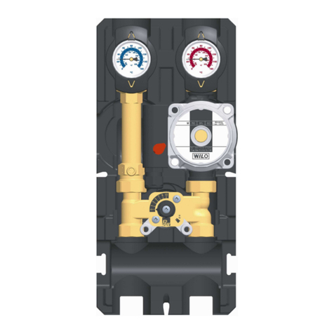
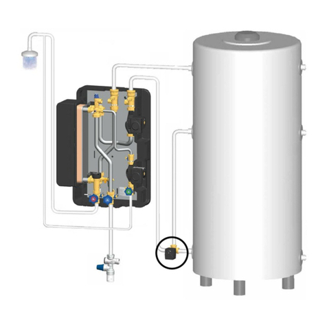
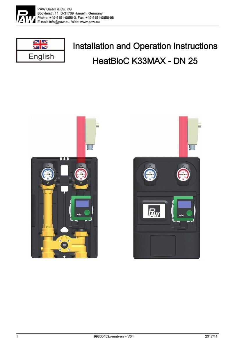
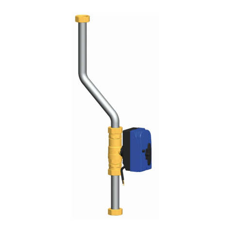
PAW K36E User manual

PAW NA Limited Partnership
45 Davis Street, Webster, Ma 01520, USA
phone: +1-508-943-4240, fax: +1-508-943-4141
email: [email protected], web: www.paw.eu
Installation and Operation Instructions
Zone Module K36E - 1¼" (DN 32)

1 For your safety
2 99473903xNA – V02 2011/11
Contents
1For your safety .................................................................................................................................................. 3
1.1About this manual ............................................................................................................................................... 3
1.2Designated use ................................................................................................................................................... 3
1.3Qualification of the installer ................................................................................................................................. 4
1.4Hand-over of the system [Specialist] ................................................................................................................... 4
1.5General safety instructions .................................................................................................................................. 5
2Product description ............................................................................................................................................ 6
2.1Function [Specialist] ............................................................................................................................................ 7
2.2Thermal control valve [Specialist]........................................................................................................................ 9
2.3Overflow valve [Specialist] ................................................................................................................................ 10
2.4Check valve [Specialist] .................................................................................................................................... 11
3Mounting and installation [Specialist] ............................................................................................................... 12
3.1Installation directly to the wall on a wall bracket [Specialist] ............................................................................. 13
3.2Installation under a distribution manifold [Specialist] ......................................................................................... 13
3.3Piping and start-up [Specialist] .......................................................................................................................... 13
4Cleaning .......................................................................................................................................................... 14
5Maintenance and decommissioning [Specialist] ............................................................................................... 14
6Spare parts ..................................................................................................................................................... 15
7Technical data and pressure drop characteristics ............................................................................................ 16
7.1Pressure drop characteristic ............................................................................................................................. 17
Item no. 99473903xNA – Version V02 – Issued 2011/11
We reserve the right to make technical changes without notice!
Printed in Germany – Copyright by PAW NA Limited Partnership
PAW NA Limited Partnership
45 Davis Street
Webster, Ma 01570, USA

1 For your safety
2011/11 99473903xNA – V02 3
1For your safety
Carefully read this manual before installation
and start-up. Non-observance of the
instructions in this manual may lead to material
damage and serious injuries that may result in
death.
¾Keep this manual in close proximity of the
system for later use.
indicates the risk of death,
serious injuries or
considerable material
damage in case the
corresponding precautions
are not observed.
indicates the risk of light
injuries in case the
corresponding precautions
are not observed.
indicates the risk of material
damage in case the
corresponding precautions
are not observed.
1.1 About this manual
This manual describes the functions,
installation, start-up and operation of the low-
temperature zone module K36E. The chapters
called [Specialist] are only referred to
specialists.
For other components of the heating system,
such as boiler, storage tanks, pressure relief
valves and controllers, refer to the instructions
of the corresponding manufacturer.
1.2 Designated use
The zone module may only be used in closed hydronic
heating systems. The zone module may not be used in
potable water applications or for process water. The
technical limit values specified in this manual must be
adhered to.
Unintended use of the zone module will invalidate any
liability claims.
Only use PAW accessories for the zone module.
The wrapping materials are made of recyclable materials
that can be recycled by standard recycling operations.

1 For your safety
4 99473903xNA – V02 2011/11
1.3 Qualification of the installer
Installation and commissioning of this equipment should
be done by qualified installers [Specialist] in accordance
with local, state and federal codes which may be
applicable.
The following must also be observed during installation
and commissioning:
•Relevant regional and national regulations (for
example Occupational Safety and Health Act)
•Relevant accident prevention regulations (for
example of the Employer's Liability Insurance
Association)
•Instructions and safety instructions mentioned in
this manual
1.4 Hand-over of the system [Specialist]
After installation and start-up, the installer is responsible
for familiarizing the end user with the functions of the
system and the basic safety measures.
¾Hand the manual over to the end user. Instruct
the end user to keep the manual in close
proximity to the system.
¾Instruct the end user to have the zone module
serviced and repaired by a specialist only. The
zone module does not contain any parts which
may be repaired by the end user.
¾Explain to the end user the functions of the
system and the safety devices. Point out to the
end user that the shell must remain mounted
during operation and that the ball valves must be
open.

1 For your safety
2011/11 99473903xNA – V02 5
1.5 General safety instructions
Before installing and putting the product into operation, you must read and observe the following safety instructions:
Risk of burns!
The valves, fittings and the pump may heat up to more than 212 °F (100 °C) during
operation.
¾The shell must remain closed during operation.
Personal injury and material damage!
The zone module is only suitable for use in heating circuits filled with heating water with
neutral pH.
¾The zone module may not be used in sanitary water applications.
¾Flush the heating circuit before installation to remove scale residues.
Material damage due to mineral oils!
Mineral oil products permanently damage the EDPM sealing elements, resulting in a loss
of their sealing characteristics. We cannot be held liable for damage caused by seals
thus damaged, nor will we offer a replacement under warranty.
¾It is imperative to prevent the EPDM sealing elements from making contact with
substances containing mineral oils.
¾Use silicone- or polyalkylene-based lubricants free of mineral oil, such as Unisilikon
L250L and Syntheso Glep 1 from the company Klüber or a silicone spray.

2 Product description
6 99473903xNA – V02 2011/11
2Product description
A-1 Supply (to the consumer circuit)
A-2 Return (from the consumer circuit)
A-6 Coupling for overhead installation
A Thermo controller (see detailed description
below)
B-1 Swivel flanges
B 3-speed heating pump
C-2 Ball valve in the return with integrated
temperature gauge handle (blue)
C-1 Return (to the boiler circuit)
D-1 Supply (from the boiler circuit)
D-2 Ball valve in the supply with integrated
temperature gauge handle (red)
E Return pipe
F Design insulation with optimized function
A-3 Thermal control valve (see page 9)
A-4 Overflow valve (see page 10)
A-5 Check valve (see page 11)

2 Product description
2011/11 99473903xNA – V02 7
2.1 Function [Specialist]
K36E serves to maintain a fixed minimum return temperature in the boiler circuit. It is used in heating installations with
solid fuel boilers, wood firing or stove heating systems. It is available in three versions for opening temperatures of 122 °F
(50 °C), 131 °F (55 °C) and 140 °F (60 °C) respectively. K36E can be directly mounted to the wall or to a PAW distribution
manifold.
Installation directly to the wall
The zone module prevents the temperature in the boiler from falling under the dew
point which reduces contamination of the boiler.
Applications:
•The zone module can be mounted separately and can be connected to a
buffer tank or a hydraulic separator. When the opening temperature of 122°F
(50°C), 131°F (55°C) or 140°F (60°C) is reached in the boiler circuit, the
pump starts to charge a tank or to separate the pressures in the hydraulic
separator.
The following figure shows the adjustments necessary for this type of installation:
Buffer tank
Solid fuel
boiler
Overflow valve closed
(adjustment knob screwed in)
Pump speed
Position 3

2 Product description
8 99473903xNA – V02 2011/11
Installation under a distribution manifold
•The zone module can be mounted under a distribution manifold. In this
system the pump exerts a pressure on the entire installation. When the
overflow valve in the thermo controller is open, the pressure can be
reduced via the valve. Undesired circulation, which could lead to
overcharging of the domestic water tank, can thus be prevented.
The following figure shows the adjustments necessary for this type of
installation:
Domestic
water tank
Overflow valve open
(adjustment knob screwed out)
Pump speed
Position 2
Solid fuel
boiler

2 Product description
2011/11 99473903xNA – V02 9
2.2 Thermal control valve [Specialist]
The thermal control valve (A-3) serves as a bypass in the start-up phase.
When the temperature of the water in the boiler circuit is lower than
the opening pressure of the thermal control valve, the valve is closed
and thus the line to the consumers. The water is circulated in the
boiler circuit through the completely open bypass.
When the water in the boiler circuit has obtained the opening
temperature (+/- 3 K), the thermal control valve opens the line from/to
the consumers. The circulation in the consumer circuit is thus
guaranteed. The cold water from the consumer return line is mixed in
the control valve with the hot water from the bypass. Depending on
the temperature and the flow rate of the water from the return line, the
thermal control valve shuts off or opens the line to the consumers.
Thus the return line which leads to the boiler always remains at a
certain temperature level.
With rising temperature from the return line of the consumers, the
thermal control valve opens the line to the consumers completely.
The temperature of the boiler return remains nearly constant
(+/- -3 K).

2 Product description
10 99473903xNA – V02 2011/11
2.3 Overflow valve [Specialist]
In systems with a distribution manifold the pump of the boiler charging set exerts a pressure on the entire installation.
When the overflow valve in the thermo controller is open, the pressure can be reduced via the valve. Undesired
circulation, which could lead to overcharging of the domestic water tank, can thus be prevented.
Overflow valve open
close
Overflow valve closed
open

2 Product description
2011/11 99473903xNA – V02 11
2.4 Check valve [Specialist]
The K36E zone module is equipped with a check valve that is integrated in the supply of the mixing valve (A-5). The
check valve is spring-operated. The opening pressure is 7.9 inch head.
Operation
During operation the mark must point to
"Z".
Æ The check valve is operating.
Æ Flow only in the direction of the arrow
Filling, draining, ventilating
For filling, draining and ventilating the
mark must point to "A".
Æ The check valve is opened
Æ Flow in both directions

3 Mounting and installation [Specialist]
12 99473903xNA – V02 2011/11
3Mounting and installation [Specialist]
Risk of electric shock!
¾Prior to commencing electrical work, pull the mains plug!
¾Only after completing all installation work, should the mains plug be plugged into a
socket! This avoids an unintentional start of the motors.
Damage to property!
¾The zone module may only be installed indoors with a power supply of 120 V / 60 Hz.
The installation site must be dry, stable and frost-free.
The zone module can be installed
•Option 1:
directly to the wall on a wall bracket.
•Option 2:
under a distribution manifold
Supply
Supply
Heat generator
Supply
Supply
Return
Return
Return
Return
Heat generator
Consumer circuit Consumer circuit

3 Mounting and installation [Specialist]
2011/11 99473903xNA – V02 13
3.1 Installation directly to the wall on a wall bracket [Specialist]
1.Fix the wall bracket (not included in delivery) to the
wall with the enclosed screws and washers.
2. Screw the zone module with the coupling piece of
overhead installation to the wall bracket.
3. Continue with "3.3 Piping and start-up [Specialist]".
3.2 Installation under a distribution manifold [Specialist]
1. Mount the distribution manifold on the PAW wall
brackets as described in the separate instructions.
Mount the zone module directly to the connections of
the manifold. Remove the plugs in the connections if
necessary.
3.3 Piping and start-up [Specialist]
1. Connect the zone module to the heating installation
by means of pipes. The hydraulic schemes for the
two assembly versions can be found on pages 7 and
8. Ensure stress-free mounting to the pipeline.
2. Connect the pump.
3. Carry out a pressure test at operating pressure.
Check all screw connections and retighten them, if
necessary.
4. Mount the front shell and the temperature gauge
handles (A-2, F-2).
1. Open the ball valves by means of the temperature
gauge handles (A-2, F-2).
2. Fill the system with treated heating water.
3. Adjust the operating pressure.
Ball valve closed Ball valve open

4 Cleaning
14 99473903xNA – V02 2011/11
4Cleaning
Risk of burns!
The valves, fittings and the pump may heat up to more than 212 °F (100 °C) during
operation.
¾The shell must remain closed when cleaning.
Clean the zone module from the outside with a damp cloth only. Never use scouring or sand-containing cleaning agents.
5Maintenance and decommissioning [Specialist]
Before maintaining and decommissioning the product, you must read and observe the following safety instructions:
Risk of electric shock!
¾Disconnect all electrical devices in the heating circuit from the power supply before
carrying out maintenance work or decommissioning!
¾Secure the electrical devices against being switched on again.
Risk of burns and scalding!
¾Before starting maintenance work or decommissioning, switch off the heat generator.
¾Wait until the heating water has cooled down to 95 °F (35 °C).
1. Switch the heat generator off and wait until the
heating water has cooled down.
2. Disconnect the controller from the power supply.
3. Connect a hose to the pet cock of the heating
system.
4. Drain the cooled-down heating water into a
suitable container.
5. Dismount the zone module.
Now you can carry out the maintenance work or dispose of
the zone module by observing the local requirements.

6 Spare parts
2011/11 99473903xNA – V02 15
6Spare parts
Item # Description
B37035E for zone modules 4739035, opening temperature 122 °F (50 °C)
B37036E for zone modules 4739036, opening temperature 131 °F (55 °C)
B37037E for zone modules 4739035, opening temperature 140 °F (60 °C)

7 Technical data and pressure drop characteristics
16 99473903xNA – V02 2011/11
7Technical data and pressure drop characteristics
K33 - 1"
Dimensions Width insulation (1) ~9.8" (250 mm)
Center distance (2) ~4.9" (125 mm)
Height insulation (3) ~18.2" (462 mm)
Mounting length (4) ~15" (382 mm)
Connections Upper connections (A-1, A-2) 2" female, flat sealing
Lower connections (D-1, C-1) 1¼" female NPT
Technical Data Maximum pressure 87 psi (6 bar)
Maximum temperature 230 °F (110 °C)
Opening temperature
Zone modules 4739035 122 °F (50 °C)
Zone modules 4739036 131 °F (55 °C)
Zone modules 4739037 140 °F (60 °C)
CV value 28.3
Opening pressure flow check valve (D-1) 7.9 inch head
Materials Valves and fittings Brass
Gaskets EPDM / NBR
Insulation EPP

7 Technical data and pressure drop characteristics
2011/11 99473903xNA – V02 17
7.1 Pressure drop characteristic
Flow rate [US gpm]
Pressure [m wc]
Pressure [ft head]
Flow rate [l/h]

PAW NA Limited Partnership
45 Davis Street
Webster, Ma 01570, USA
www.paw.eu
Phone: +1-508-943-4240
Fax: +1-508-943-4141
Other manuals for K36E
2
Table of contents
Other PAW Control Unit manuals
Popular Control Unit manuals by other brands

Watts
Watts LF70A Series instructions

Farfisa
Farfisa Alba AB3G Get started

Bristan
Bristan OP TS1503 EL C Installation instructions and user guide

Miele professional
Miele professional A 315 operating instructions

Minarik
Minarik DLC500 user manual

Comunello
Comunello QUAD - 24V - 2M Installation and user manual