PAW HeatBloC K34 DN 25 User manual

PAW GmbH & Co.KG
Böcklerstr. 11, D-31789 Hameln, Germany
Phone: +49-5151-9856-0, Fax: +49-5151-9856-98
E-mail: [email protected], Web: www.paw.eu
2015/07 9939062x-mub-en – V10 1
Installation and Operation Instructions
K34 HeatBloC - DN 32

1 General information
2 9939062x-mub-en – V10 2015/07
Item no. 9939062x-mub-en - Version V10 – Issued 2015/07
Translation of the original instructions
We reserve the right to make technical changes without notice!
Printed in Germany – Copyright by PAW GmbH & Co. KG
PAW GmbH & Co.KG
Böcklerstr. 11
31789 Hameln, Germany

1 General information
2015/07 9939062x-mub-en – V10 3
Contents
1General information ............................................................................................................. 4
1.1Scope of these instructions ............................................................................................ 4
1.2Designated use .............................................................................................................. 4
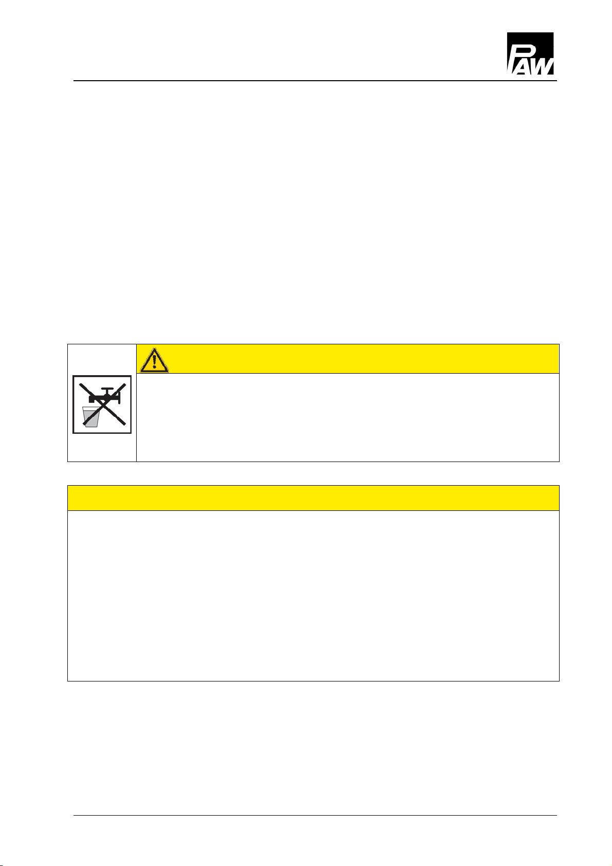
2Safety instructions ............................................................................................................... 5
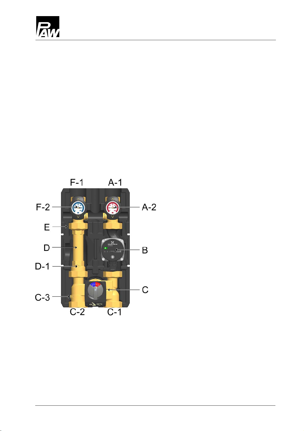
3Product description.............................................................................................................. 6
3.1Equipment ...................................................................................................................... 6
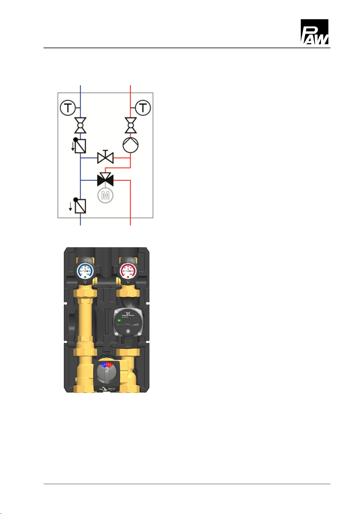
3.2Function ......................................................................................................................... 7
3.2.1Check valve and non return valve .......................................................................... 8
3.2.2Pump [specialist] ..................................................................................................... 9
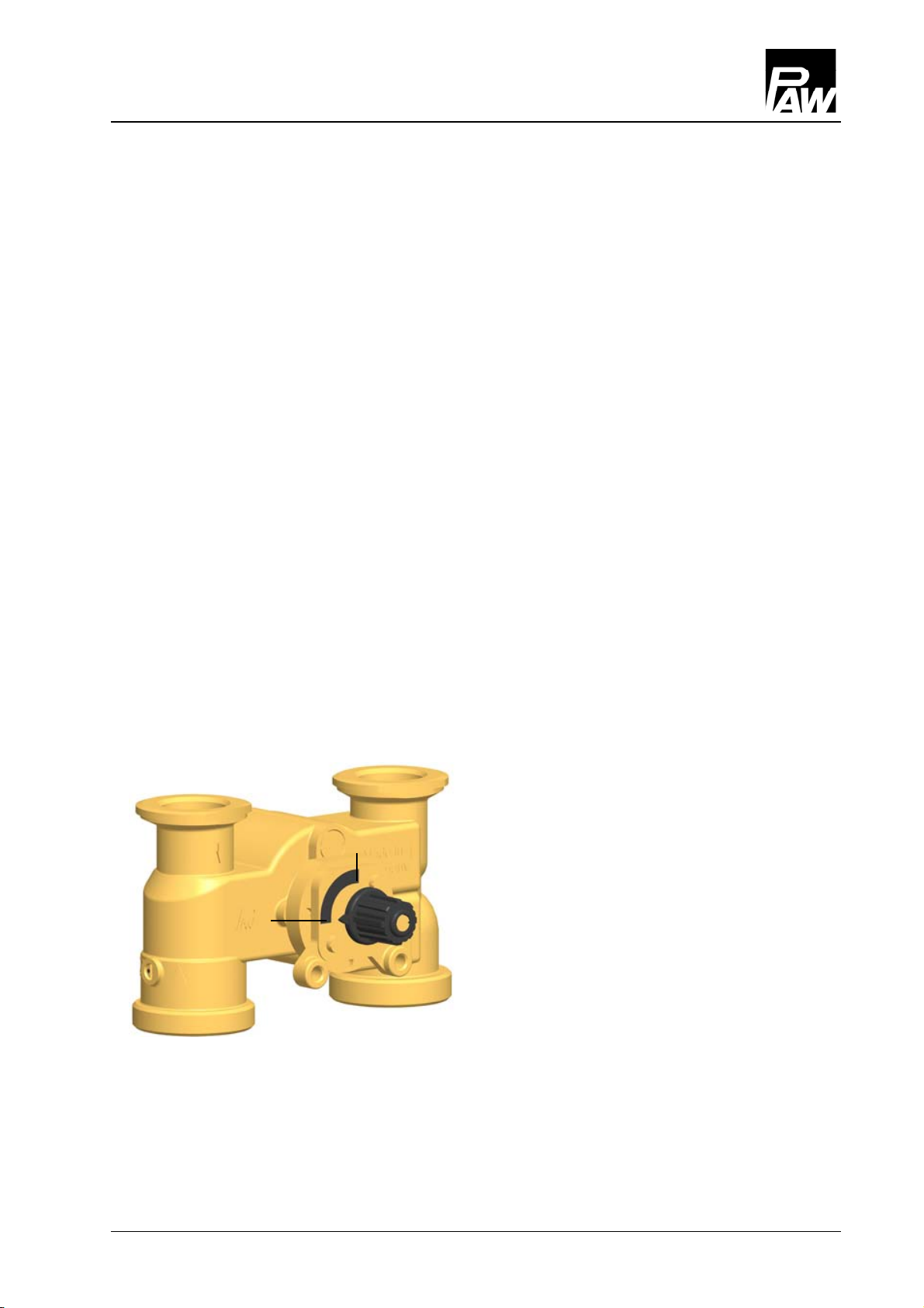
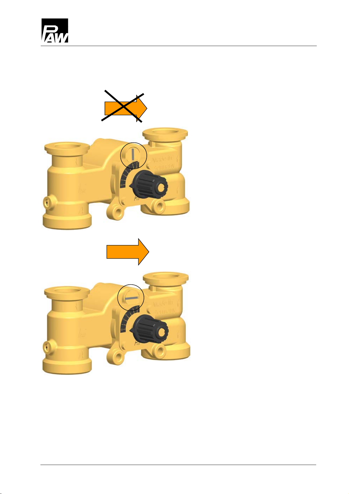
3.2.33-way mixing valve [specialist] ................................................................................ 9
3.2.4Accessories: actuator (not included in delivery) ................................................... 13
4Assembly and installation [specialist] ................................................................................ 14
4.1Installation of the modular distribution manifold / wall bracket with mounting plate ..... 14
4.2Installation of the HeatBloC and commissioning .......................................................... 15
5Scope of delivery [specialist] ............................................................................................. 17
6Technical data ................................................................................................................... 18
6.1Pump and pressure drop characteristics ..................................................................... 19

1 General information
4 9939062x-mub-en – V10 2015/07
1General information
Carefully read these instructions before installation and commissioning.
Save these instructions in the vicinity of the installation for future reference.
1.1 Scope of these instructions
These instructions describe the function, installation, commissioning and operation of the
K34mixed HeatBloC. For other components of the installation, such as pumps, controllers or the
distribution manifold, see the manufacturers' instructions. The chapters called [specialist] are
intended for specialists only.
1.2 Designated use
The HeatBloC may only be used in hydronic heating closed-loop systems taking into
consideration the technical limit values indicated in these instructions. The HeatBloC must not
be used in domestic water applications. Improper usage excludes any liability claims.
Only use PAW accessories with the HeatBloC.
The wrapping materials are made of recyclable materials and can be disposed of with
recyclable materials.

2 Safety instructions
2015/07 9939062x-mub-en – V10 5
2Safety instructions
The installation and commissioning as well as the connection of electrical components require
technical knowledge commensurate with a recognised vocational qualification as a fitter for
plumbing, heating and air conditioning technology, or a profession requiring a comparable level
of knowledge [specialist]. The following must be observed during installation and
commissioning:
relevant local and national regulations
accident prevention regulations of the professional association
instructions and safety instructions mentioned in this manual
CAUTION
Personal injury and damage to property!
The HeatBloC must only be used in hydronic heating closed-loop systems filled
with heating water according to VDI 2035 / Ö-Norm H 5195-1.
The HeatBloC must not be used in domestic water applications.
NOTICE
Material damage due to mineral oils!
Mineral oil products cause lasting damage to seals made of EPDM, whereby the sealant
properties are lost. We do not assume liability nor provide warranty for damage to property
resulting from sealants damaged in this way.
It is imperative to avoid that EPDM gets in contact with substances containing mineral
oils.
Use a lubricant based on silicone or polyalkylene and free of mineral oils such as
Unisilikon L250L and Syntheso Glep 1 of the Klüber company or a silicone spray.

3 Product description
6 9939062x-mub-en – V10 2015/07
3Product description
The K34 HeatBloC is a preassembled fitting group for hydronic heating closed-loop systems.
The pump can be isolated by means of the ball valves and the mixing valve. Thus, you can
maintain the pump without draining the heating circuit.
The PAW HeatBloC is designed such that it can be directly mounted onto a PAW distribution
manifold or a mounting plate with thread connections. With adaptor connections, the HeatBloCs
can also be installed on distribution manifolds with other dimensions.
3.1 Equipment
A-1 Flow (consumer circuit)
A-2 Full metal thermometer
with immersion sleeve integrated in
the ball valve (flow)
B Heating pump
C 3-way mixing valve
with adjustable bypass 0-50 %
C-1 Flow (boiler)
C-2 Return (boiler)
C-3 Non return valve, can be opened
D-1 Check valve, can be opened
D Return pipe
E Design insulation
with optimised function
F-2 Full metal thermometer
with immersion sleeve integrated in
the ball valve (return)
F-1 Return (consumer circuit)

3 Product description
2015/07 9939062x-mub-en – V10 7
3.2 Function
K34 3-way mixing valve with bypass 0-50 %
The flow temperature of the HeatBloC is controlled
by the integrated mixing valve. Hot water from the
boiler and cold return water are mixed to obtain the
desired flow temperature. The mixing valve is
adjusted via an external controller and an electric
actuator.
The rate of premixing is adjusted at the mixing valve
bypass and a certain amount of cold return water is
mixed to the flow water. The three-way actuator can
work over the whole adjustment range (0-100%),
although only a small amount of water from the boiler
is necessary.
Example: Radiant floor or wall heating is operated
with a low temperature level and low temperature
differences, but high flow rates. It is therefore
sufficient to "inject" a small amount of hot water into
the warm return water.
The K34 has a lower pressure loss than the K33.
Applications:
Consumer circuits with considerably lower
flow temperatures than the boiler flow
temperature
Control of radiant floor or wall heating

3 Product description
8 9939062x-mub-en – V10 2015/07
3.2.1 Check valve and non return valve
The HeatBloC is equipped with a check valve (D-1, opening pressure 200 mm wc) in the return
pipe and a non return valve (C-3, opening pressure 50 mm wc) in the mixing valve return.
They can be opened manually.
Operation
During operation, both marks must point to "Z" (closed).
The check valve and the non return valve are closed.
Flow only in the direction of the arrow.
Filling, emptying, bleeding
For filling, emptying and bleeding the mark must be
directed to "A".
The check valve and the non return valve are open.
Flow in both directions.

3 Product description
2015/07 9939062x-mub-en – V10 9
3.2.2 Pump [specialist]
The pump can be completely isolated. It can be replaced and maintained without draining of the
heating installation.
Isolation of the pump:
1. Disconnect the expansion tank from the installation.
2. Close the ball valves in the flow and the return (A-2, F-2).
3. Take off the actuator from the mixing valve.
4. Turn the bypass screw of the mixing valve so that the slot is in a vertical position.
5. Turn the nose of the valve cock so that the mixing valve is closed (for flow on the right:
nose points downwards, for flow on the left: nose points to the right).
The mixing valve is now closed.
3.2.3 3-way mixing valve [specialist]
The three-way mixing valve (C) driven by an electric motor adjusts the flow temperature of the
consumer circuit to the desired value in combination with a flow sensor and the controller.
The mixing valve is equipped with a bypass which can be adjusted separately. Cold return
water flows through the bypass into the flow, thus increasing the flow rate in the HeatBloC.
Position 10: Passage,
no mixing, flow temperature
consumer = flow temperature
boiler
Position 0: 100% mixing
flow temperature consumer =
return temperature consumer
10
0

3 Product description
10 9939062x-mub-en – V10 2015/07
1. Determine the optimum bypass position during commissioning in a trial-and-error
process.
When the slot of the bypass screw
is in a vertical position, the bypass is
closed (normal operation).
When the slot of the bypass screw
is in a horizontal position, the
bypass is completely open.
This allows the highest possible flow
rate from the return to the flow line.
This adjustment may be necessary
for radiant floors requiring a very
high flow rate. The flow temperature
is low and the control may be
negatively affected.
2. Check the bypass position during operation. Make sure that the flow rate is sufficient and
that the desired temperature is reached.

3 Product description
2015/07 9939062x-mub-en – V10 11
Change of the flow line [specialist]
Dismounting the mixing valve
1. Take off the thermometer handles (A-2, F-2) and remove the insulating front shell.
2. Take the HeatBloC out of the insulating back shell.
3. Dismount the mixing valve (C).
Conversion of the mixing valve
1. Unscrew the screw (1).
2. Take the rotary knob (2) off the rod of the cock.
3. Unscrew the screw (3).
4. Take off the cover plate (4).
5. Unscrew the two screws (5).
6. Remove the front plate (6).
7. Extract the sealing bush (7) and the valve cock (8) from the mixing valve body.
8. Unscrew the screws (10) on the rear side of the mixing valve.
9. Take off the cover (9) on the rear side and fix it at the other side of the mixing valve
using the screws (10).
10. Insert the sealing bush (7) and the valve cock (8) into the channel of the mixing valve.
11. Fix the front cover (6) with the screws (5).

3 Product description
12 9939062x-mub-en – V10 2015/07
12. Turn the cover plate (4) such that the designation PAW is at the bottom and the scale is
located as can be seen in the figure above.
13. Fix the cover plate (4) with the screws (3).
14. Put the rotary knob (2) onto the cock rod.
15. Fix the rotary knob (2) to the cock (8) with the screw (1).
Modification and commissioning of the heating circuit
1. Interchange the return pipe (D) and the flow pipe and the pump (B).
Consider the flow direction of the pump!
Turn the pump head such that the terminal head is directed to the top or to the centre of the
heating circuit.
2. Dismount and interchange the ball valves.
3. Mount the HeatBloC and connect it to the installation.
4. Check all union nuts before commissioning and firmly tighten them if necessary.
5. Mount the insulation after the pressure test.
Mount the thermometer handles (A-2, F-2).
Mixing valve with flow on the right Mixing valve with flow on the left
Flow
Flow

3 Product description
2015/07 9939062x-mub-en – V10 13
3.2.4 Accessories: actuator (not included in delivery)
The PAW actuator for weather-compensated control is available as an accessory. For mixing
valves with flow on the left, the scale must be turned by 180°.
for mixing valves with flow on the right for mixing valves with flow on the left
Assembly of the actuator for mixing
valves with flow on the right:
1. Turn the rotary knob of the mixing
valve to position 0.
2. Set the actuator to manual mode
by turning the selector switch.
3. Turn the rotary lever of the
actuator to the left to the position
shown in the figure.
4. Put the actuator onto the rotary
knob of the mixing valve and the
two stop bolts.
5. Set the actuator to automatic
mode.
Stop bolt

4 Assembly and installation [specialist]
14 9939062x-mub-en – V10 2015/07
4Assembly and installation [specialist]
The K34 HeatBloC must be either installed on a PAW modular distribution manifold or a set of
wall bracket and mounting plate. The modular distribution manifold, the wall bracket and the
mounting plate are not included in delivery.
NOTICE
Damage to property!
The location of installation must be dry, load-carrying, frost-proof and protected against
ultraviolet radiation to prevent material damage to the installation.
4.1 Installation of the modular distribution manifold / wall bracket with mounting plate
Mount the modular distribution manifold or the wall bracket with mounting plate as described in
the separate instructions.
If possible, choose the largest distance to the wall.
In this way it is easier to mount the insulation of the
distribution manifold.

4 Assembly and installation [specialist]
2015/07 9939062x-mub-en – V10 15
4.2 Installation of the HeatBloC and commissioning
The HeatBloC can be installed
Option 1: on a PAW modular distribution
manifold.
Option 2: on a mounting plate with
thread connections.
Flow
Flow
Boiler circuit
Flow
Flow
Return
Return
Return
Return
Boiler circuit
Consumer circuit Consumer circuit

4 Assembly and installation [specialist]
16 9939062x-mub-en – V10 2015/07
1.Take off the thermometer handles
(A-2, F-2) and remove the insulating
front shell of the HeatBloC.
2. Unscrew the nuts on the lower
connections of the HeatBloC and
take out the sealing rings.
3. Flip the two nuts over the flanges.
4.Insert the sealing rings into the nuts.
5. Put the HeatBloC onto the two nuts.
6. Tighten the nuts.
Take care that the nuts do not get
jammed and that the sealing rings do
not slip.
7.Connect the HeatBloC to the
installation. The connections to the
installation must be stress-free.
8. Connect the pump.
9. Carry out the pressure test and check
all thread connections.
10. Mount the insulating front shell and
the thermometer handles (A-2, F-2).
Flange
(
to
p
view
)
Nut
1
2
3
Flange
(
side view
)
Sealing ring

5 Scope of delivery [specialist]
2015/07 9939062x-mub-en – V10 17
5 Scope of delivery [specialist]
NOTICE
Complaints and requests/orders of spare parts will only be processed with information on the
serial number!
The serial number can be found on the return pipe of the heating circuit.
Item no. Description
37013 Sealing set for mixing valve
Pump Item number
Wilo-Yonos PARA RS 30/6-RKA E1236056
Wilo-Stratos PICO 30/1-6 E1239630
Wilo-Stratos PARA 30/1-8 E12395123
Grundfos UPM3 Auto L 32-70 PP3 E1212560
Grundfos Alpha2 32-60 E121701
Grundfos UPML 32-95 Auto E121704

6 Technical data
18 9939062x-mub-en – V10 2015/07
6Technical data
K34 DN 32 (1¼")
Dimensions
Centre distance (1) 125 mm
Width insulation (2) 250 mm
Height insulation (3) 438 mm
Installation length (4) 385 mm
Connections
Outlet (A-1, F-1) 1¼" internal thread
Inlet (C-1, C-2) 2" external thread
Technical data
Opening pressure check valve (D-1) 200 mm wc, can be opened
Opening pressure non return valve (C-3) 50 mm wc, can be opened
Materials
Valves and fittings Brass
Gaskets EPDM / NBR
Insulation EPP

6 Technical data
2015/07 9939062x-mub-en – V10 19
K34 DN 32 (1¼")
Hydraulics
Maximum pressure 6 bars
Maximum temperature 110 °C
KVS value [m3/h] 10.8
6.1 Pump and pressure drop characteristics
Pressure [m wc]
Pressure [kPa]
Flow rate [l/h]

PAW GmbH & Co.KG
Böcklerstraße 11
D-31789 Hameln, Germany
www.paw.eu
Phone: +49 (0) 5151 9856- 0
Fax: +49 (0) 5151 985698
9939062x-mub-en – V10 2015/07
Other manuals for HeatBloC K34 DN 25
1
Table of contents
Other PAW Heating System manuals

PAW
PAW HeatBloC K38 DN 25 Owner's manual

PAW
PAW HeatBloc MC42 User manual

PAW
PAW HeatBloC MC 41 DN 25 User manual

PAW
PAW HeatBloC MC46 DN 25 User manual

PAW
PAW HeatBloC K36E - DN 25 User manual

PAW
PAW CoolBloC C34 DN 32 User manual

PAW
PAW HeatBloC K32-DN 25 User manual

PAW
PAW HeatBloC MC45 DN 25 User manual
Popular Heating System manuals by other brands

DEVI
DEVI Devifoil Mirror installation instructions

Buderus
Buderus FM443 Installation and service instructions

Etherma
Etherma 9120054178607 Installation and operating instructions

SAMITECH
SAMITECH Heat Wrap Smart instruction manual

EarthLinked Technologies
EarthLinked Technologies Prime-025 Quick start instructions

Carrier
Carrier 48DD Product data