PCC AVK AL Series Instructions for use

AVK INDUSTRIAL PRODUCTS
IJ!'!~
AriAieompany
THREADED INSERTS FOR INDUSTRV
z
c
c:
en
-f
JJ
:J>
r-
-f
::I:
JJ
m
:J>
c
m
c
-
z
en
m
JJ
-f
en

lNTBODUCTIQN .• ".
Read manual before operating tool.
You now own the finest insert installation tool on the market today. These durable tools provide many years of trouble free
operation if you will simply follow the instructions in this manual.
Prior to use, certain checks must be made. This tool requires the proper air line setup, lubrication, and air pressure to set the
desired inserts.
AIRf~IH§::IErUP
Every ARO Air Tool is designed and built to yield the longest possible useful life, with a minimum amount of servicing. Since an air
tool is a precision machine whose working parts mate with close tolerances, it should receive the same reasonable care as any
other machine tool. Here are a few simple practices that will keep your ARO Air Tool in top operating condition.
KEEP AIR SUPPLY CLEAN. All compressed air carries varying amounts of dust, scale, moisture and other foreign matter that
should be removed by proper filtering. Failure to keep air supply clean will result in excessive wear on working parts. Therefore,
we recommend the installation of an air line filter. If your tool is equipped with a built-in air strainer, remove and clean the strainer
periodically. Always blowout the air hose before attaching to tool.
LtJ~lil~I,Oftf··
USE AIR LINE LUBRICATOR. Air tool motors operate at extremely high speeds, and must have proper oil lubrication. An air line
lubricator should be installed and oil supply properly regulated. Your ARO Distributor can furnish the correct combination air line
filter and oiler. Some units can service up to three tools simultaneously. As a further precaution, put a few drops of light oil in air
inlet of tool before attaching tool to air line for the first time.
RECOMMENDED LUBRICANTS: Spindle Oil 29665 (I qt. container) for oiler and air inlet.
FILTERED AND OILED AIR will allow the tool to operate more efficiently and yield a longer life to operating parts and
mechanisms. A line filter capable of filtering particles larger than 50 microns should be used with a line oiler.
FILTER-REGULATOR-OILER combination (F-R-L) Model 28231-810 is recommended for use with this Air Tool. The capacity of
the individual Filter-Oiler is adequate to provide clean (40 micron), oiled and regulated air for the tool. AIR CONSUMPTION:
Approximately 25 SCFM.
RECOMMENDED HOSE SIZE: 5/16" nominal inside diameter.
oalJ\jMlNt PROPER AIR PRESSURES
AVK's power installation tools have been designed to operate at the listed "Dynamic" P. S.1.ratings at the air inlet of the tool. Even
though the in-line pressure gage may show the proper pressure, the use of long hoses, quick-disconnects and other couplers
between the gage and the tool can adversely affect the tool's performance. A simple test, so you may correlate our required P. S.1.
setting with your set-up is:
1. Connect a 1/4" short pipe nipple into the tool's air inlet.
2. Screw a 1/4" pipe tee onto the pipe nipple and put an air gage into the upright leg of the pipe tee.
3. Connect the air supply to the pipe tee using the actual hose, fittings, couplers or connectors that will be used.
4. Now, check the P.S.1.on the test gage at the air tool inlet with the tool running. Adjust, as necessary, the air pressure regulator
so that the P.S.1.required is shown on the test gage. Note the reading on the in-line pressure gage. It will probably read a higher
P. S.1.than the gage at the tool. The figure on the in-line gage is the "Adjusted Dynamic P.S.I." Use this figure when using the tool
in that location with that hose set-up.
5. Remove tee, nipple and gage, connect air supply directly to tool and begin production.
Test dynamic air pressure readings at the
location where the tool is to be operated*
(Instructions, fig. 3)
2
Adjust the in-line air pressure regulator so that dynamic
pressure is in accordance with AVK's power tool specs
at the air tool inlet.
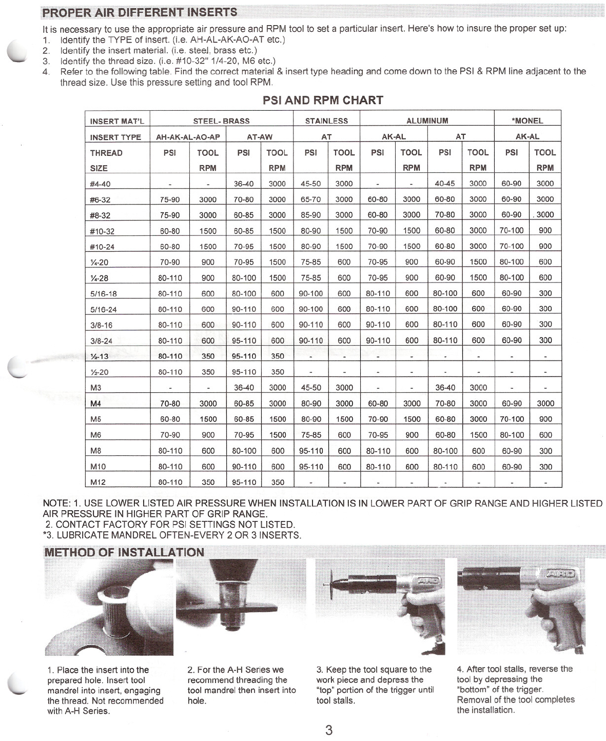
It is necessary to use the appropriate air pressure and RPM tool to set a particular insert. Here's how to insure the proper set up:
1. Identify the TYPE of insert. (i.e. AH-AL-AK-AO-AT etc.)
2. Identify the insert material. (i.e. steel, brass etc.)
3. Identify the thread size. (i.e. #10-32" 1/4-20, M6 etc.)
4. Refer to the following table. Find the correct material & insert type heading and come down to the PSI & RPM line adjacent to the
thread size. Use this pressure setting and tool RPM.
PSI AND RPM CHART
INSERT MAT'L STEEL- BRASSSTAINLESSALUMINUM
'MONEL
INSERT TYPE
AH-AK-AL-AO-APAT-AWATAK-ALATAK-AL
THREAD
PSITOOLPSITOOLPSITOOLPSITOOLPSITOOLPSITOOL
SIZE
RPMRPMRPMRPMRPM
RPM
#4-40
-
-
36-40
300045-503000
-
-
40-45
300060-903000
#6-32
75-90
300070-80300065-70300060-803000
60-80
300060-90
3000
#8-32
75-90300060-85
3000
85-903000
60-80
300070-80
300060-90
.3000
#10-32
60-80150060-85
1500
80-90150070-90150060-80300070-100900
#10-24
60-80150070-95150080-90150070-90150060-80300070-100900
X,-20
70-9090070-95150075-8560070-9590060-90150080-100600
X,-28
80-11090080-100150075-8560070-9590060-90150080-100600
5/16-18
80-11060080-10060090-10060080-11060080-100
60060-90
300
5/16-24
80-11060090-11060090-10060080-11060080-10060060-90
300
3/8-16
80-11060090-11060090-11060090-11060080-11060060-90300
3/8-24
80-11060095-11060090-11060090-11060080-11060060-90300
%-13
80-11035095-110350
-
-
------
%-20
80-11035095-110350
-
-
------
M3
-
-
36-40
3000
45-50
3000
-
-
36-40
3000
-
-
M4
70-80300060-85300080-90
3000
60-80300070-80300060-903000
M5
60-80150060-85150080-90
1500
70-90150060-80300070-100900
M6
70-9090070-95150075-8560070-9590060-80150080-100600
M8
80-11060080-10060095-110
600
80-11060080-10060060-90
300
M10
80-11060090-11060095-110
600
80-11060080-11060060-90300
M12
80-11035095-110350
-
-
-
----
-
NOTE: 1. USE LOWER LISTED AI R PRESSURE WHEN INSTALLATION IS IN LOWER PART OF GRIP RANGE AND HIGHER LISTED
AIR PRESSURE IN HIGHER PART OF GRIP RANGE.
2. CONTACT FACTORY FOR PSI SETTINGS NOT LISTED.
*3. LUBRICATE MANDREL OFTEN-EVERY 2 OR 3 INSERTS.
1. Place the insert into the
prepared hole. Insert tool
mandrel into insert, engaging
the thread. Not recommended
with A-H Series.
2. For the A-H Series we
recommend threading the
tool mandrel then insert into
hole.
3. Keep the tool square to the
work piece and depress the
"top" portion of the trigger until
tool stalls.
3
4. After tool stalls, reverse the
tool by depressing the
"bottom" of the trigger.
Removal of the tool completes
the installation.

Power ranges have been carefully selected to assure proper insert
installation. One RPM tool may be used to set various thread size
inserts as shown in the PSI and RPM chart. Be sure to match the RPM of
the tool to the insert thread size, and insert material.
Complete tool adaption kit (CTA) is that portion of the tool that is
screwed onto the air motor to make a AVK insert tool. (Left hand thread)
Thread adaption kit, (TAK) is the portion of the CTA that is disengaged
by activation of the "quick release mechanism". Note the following
illustrations.
A~H,'A-K,A-L, A-O AND A-P SERIES INSERT THREAD ADAPTION KITS
AND COMPON.E.NT Pl2:Rrr~UI-1:BERS •
.{:'>:':. <:.'-, _;"''''' "" """" ,,,. •••• _:."","", :.:'''.'.''''''~''':. ;«_,co..,. ." .. :.:::;:;;;; ..... ,,;: .. ,,~ .. ~.,.,
fOR SIZES 16. 18 ~ "' .•
I
J
I
,I
socl<n 32PT)<
HE/o.D '\ ~~ING
"fSCR£W{
f )
Jill
CO~PLETE
l )l
----.'v~----- ------.'v ....
COMMON TO ALL TOOLS THREAD ADAPTATION KIT (T .AI<)
l-----------''v~
TOOL ADAPTATION (CTA~
*Nozzle design for AH,AK,AL,AO and AP Series Insert
Installation - Do not use for AT,AW or RN Series insert installation.
THREAD CTA
TAK
HEX*SOCKET HEAD
BEARING
NOSE CONE
SIZE PART NO.PART NO.DRIVE
CAP SCREWSET
#6-32 AKPT632 CTAAKPT632 TAK29NPT22
#6-32 x 1 1/2"
32PTI
77AKPT6
#8-32 AKPT832 CTAAKPT832 TAK
29NPT23
#8-32 x 1 1/2"
32PT277AKPT8
M4xO.7 AKPT470 CTAAKPT470 TAK
29NPT24M4 x 40mm 32PT3
77AKPT470
#10-24 AKPTl024 CTAAKPTI024 TAK29NPT4
#10-24 x 1 3/4"
32PT4
77AKPTI0
#10-32 AKPTl032 CTAAKPTl032 TAK29NPT4
#10-632 x 1 3/4"
32PT4
77AKPTlO
M5xO.8 AKPT580 CTA
AKPT580 TAK
29NPTlO
M5 x 45mm 32PT477AKPT580
1/4-20 AKPT420 CTA
AKPT420 TAK29NPT5
1/4-20 x 1 1/2"
32PT5
77AKPT250
1/4-28 AKPT428 CTA
AKPT428 TAK
29NPT5
1/4-28 x 1 1/2"
32PT5
77AKPT250
M6xl.0 AKPT610 CTA
AKPT610 TAK29NPTll
M6 x 40mm 32PT677AKPT610
5/16-18 AKPT518 CTA
AKPT518 TAK
29NPT6
5/16-18 x 2"
32PT777AKPT3125
5/16-24
AKPT524 CTAAKPT524 TAK
29NPT6
5/16-24 x 2"
32PT7
77AKPT3125
M8xl. 25 AKPT8125 CTA
AKPT8125 TAK29NPT12M8 x 50mm 32PT777AKPT8125
3/8-16
AKPT616 CTAAKPT616 TAK29NPT7
3/8-16 x 2"
32PT877AKPT375
3/8-24
AKPT624 CTAAKPT624 TAK29NPT7
3/8-24 x 2"
32PT8
77AKPT375
MI0xl. 5
AKPTl015 CTAAKPTl015 TAK29NPT25MI0 x 50mm 32PTI077AKPT1015
1/2-13
AKPT813 CTA
NOT AVAILABLE29NPT26
1/2-13 x 2500
30NPT50077AKPT500
1/2-20 AKPT820 CTA
NOT AVAILABLE29NPT26
1/2-20 x 2500
30NPT50077AKPT500
I-...
M12xl.75
AKPT12175 CTANOT AVAILABLE29NPT27M12 x 60mm 30NPT500
77AKPTM12 -U'
~
*NOTE: Use high quality alloy steel socket head cap screws such as "UNBRAKO®" by SPS
4
BEARING AS5EMBLIES
CONCAVE
BE••••RING RAc[
HAT SECTION
BEARING RACE
/'
L- FLAT BEARING RACE
ref: SIltS 14, fli. 18, it} &: 1.14
SOCKET JOPTX 7~iPTX
HEAD ~EARING \' NOSE
CAPSCREW SET \CONE
\
.\
\tW-ED-
SERIES
ERS
COMMON TO ALL TOOLS
l _ ,,'
COMPLETE TOOL ADAPT ATION (CT A)
SERIES.? AN
~QNJ?ONENT PAR
8AKPT113 21QNPT100
SPRING '\ HOUSING
33NPT100Gl"'5'3Y ....
.- SOUAR[ DRiVE
\, ADAPTOR
l -..../ Jl~-------.v.------)
THREAD ADAPTATION KIT (TAl<)
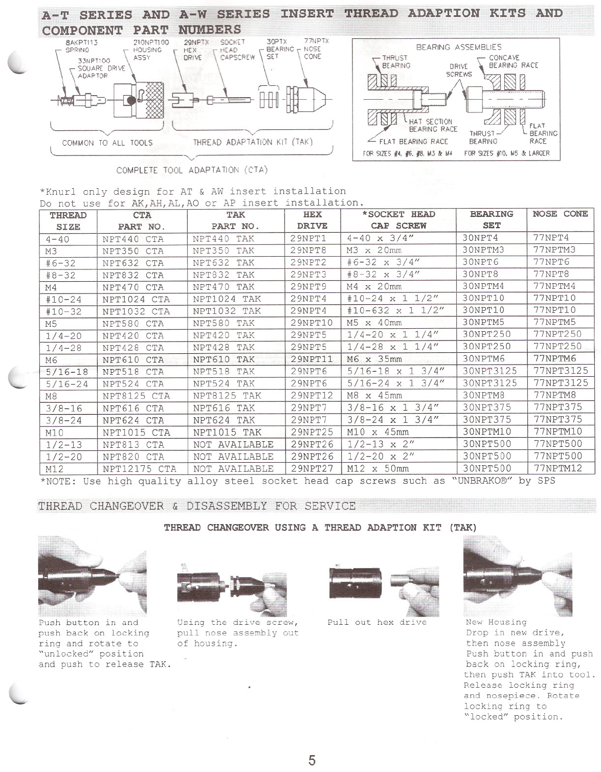
*Knurl only design for AT & AW insert installation
Do not use for AK,AH,AL,AO or AP insert installation.
THREAD CTATAKHEX
*SOCKET HEAD
BEARINGNOSE CONE
SIZE
PART NO.PART NO.DRIVECAP SCREWSET
4-40
NPT440 CTANPT440 TAK29NPT1
4-40 x 3/4"30NPT4
77NPT4
M3
NPT350 CTANPT350 TAK29NPTSM3 x 20mm 30NPTM377NPTM3
#6-32
NPT632 CTANPT632 TAK29NPT2
#6-32 x 3/4"30NPT6
77NPT6
#8-32
NPT832 CTANPTS32 TAK29NPT3
#S-32 x 3/4"
30NPTS
77NPTS
M4
NPT470 CTANPT470 TAK29NPT9M4 x 20mm 30NPTM4
77NPTM4
#10-24
NPT1024 CTANPTl024 TAK29NPT4
#10-24 x 1 1/2"30NPT10
77NPT10
#10-32
NPT1032 CTANPT1032 TAK29NPT4
#10-632 x 1 1/2"
30NPT10
77NPT10
M5
NPT5S0 CTANPT5S0 TAK29NPT10M5 x 40mm 30NPTM577NPTM5
1/4-20
NPT420 CTANPT420 TAK29NPT5
1/4-20 x 1 1/4"
30NPT250
77NPT250
1/4-2S
NPT42S CTANPT42S TAK29NPT5
1/4-2S x 1 1/4"
30NPT25077NPT250
M6
NPT610 CTANPT610 TAK29NPTllM6 x 35mm 30NPTM677NPTM6
5/16-1S
NPT51S CTANPT51S TAK29NPT6
5/16-1S x 1 3/4"
30NPT3125
77NPT3125
5/16-24
NPT524 CTANPT524 TAK29NPT6
5/16-24 x 1 3/4"30NPT3125
77NPT3125
MS
NPTS125 CTANPTS125 TAK29NPT12MS x 45mm 30NPTMS
77NPTMS
3/S-16
NPT616 CTA
NPT616 TAK29NPT7
3/8-16 x 1 3/4"
30NPT375
77NPT375
3/8-24
NPT624 CTANPT624 TAK29NPT7
3/S-24 x 1 3/4"
30NPT375
77NPT375
M10
NPT1015 CTA
NPT1015 TAK29NPT25M10 x 45mm30NPTM1077NPTM10
1/2-13
NPTS13 CTANOT AVAILABLE
29NPT26
1/2-13 x 2"
30NPT50077NPT500
1/2-20
NPTS20 CTA
NOT AVAILABLE
29NPT26
1/2-20 x 2"
30NPT500
77NPT500
M12 NPT12175 CTANOT AVAILABLE29NPT27M12 x 50mm30NPT50077NPTM12
*NOTE: Use high quality alloy steel socket head cap screws such as "UNBRAKO®" by SPS
THREAD CHANGEOVER
THREAD CHANGEOVER USING A THREAD ADAPTION KIT (TAK)
=
Push button in and
push back on locking
ring and rotate to
"unlocked" position
and push to release TAK.
Using the drive screw,
pull nose assembly out
of housing.
Pullout hex drive New Housing
Drop in new drive,
then nose assembly
Push button in and push
back on locking ring,
then push TAK into tool.
Release locking ring
and nosepiece. Rotate
locking ring to
"locked" position.
5
COMPl.ETE TOOL ADAPTATION (CTA)
~.EARINi
RACE
, 0
8~...==..~..3
..............................
~~n~
~ST BEARING
)
'-/
THREAD ADAP'A TION KIT (TAK)
)~
210NP11QO 29NPTX SOCKET 32PTX 77ARPTX
HOUSING '\ HEX \" HEAD __ BEARING \ NOSE
"" ~~~ \"'"'~ \ ' •.•ET \ CONE
\ ,L,~- -- HH1lJ}
'-/
COMMON TO ALL TOOLS
8AKPT113
\ SPRI,\G -
33N°T100
, __ SOUARE DRIVE
~:C"
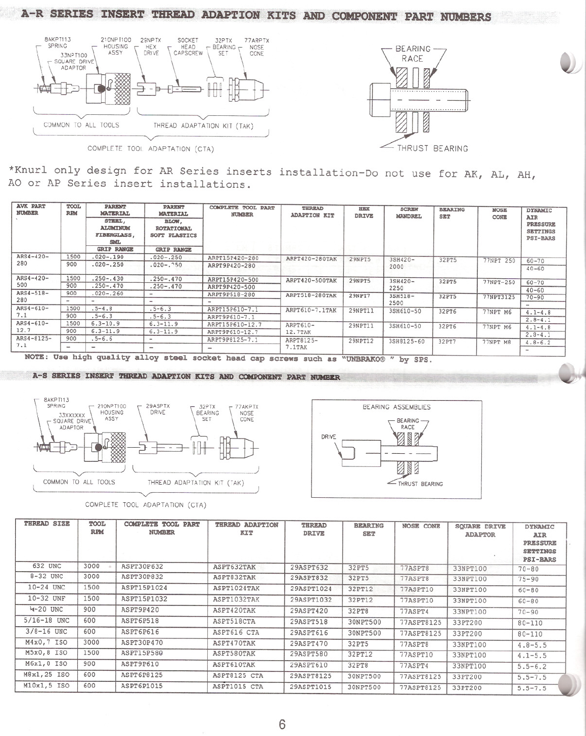
*Knurl only design for AR Series inserts installation-Do not use for AK, AL, AH,
AO or AP Series insert installations.
AVlt PART TOOLPAREN'l'PARENT
cacPLETE TOOL PARTTHREAD
IIBXSCl\IlW
BKARING1I0SB
DmAKIC
NOIIIlZR IU'MlCATBIUAL
MA'l'ZIUAL
NOIIIlZRADAPTIOII ItITDIUVB
IIAIlDIUILSIlTCONII
AIR
STEEL, BLOW, PRBSSORBALtJNDIUM RO'rATIOHAL SBTTINGS
I'IllBRGLASS , SOFT PLASTICS PSI-BARS
SML GRIP RANGE GRIP RANGE
ARS4-420- 1500.020- .190 .020-.250
ARPT15P420-280ARPT420-280TAK
29NPT5
3SH420-
32PT5
77NPT 250
60-70
280 900
.020-.250 .020-. "50
ARPT9P420-280 2000
40-60
ARS4-420-
1500.250-.430 .250-.470
ARPT15P420-500ARPT420-500TAK
29NPT53SH420-
32PT577NPT-25060-70
500 900.250-.470 .250-.470
ARPT9P420-500 2250
40-60
ARS4-518- 900
.020-.260 -ARPT9P518-280
ARPT518-280TAK
29NPT73SH518-32PT5
77NPT3125
70-90
280 -
--
-2500
-
ARS4-610- 1500.5-4.8 .5-6.3
ARPT15P610-7.1
ARPT610-7.1TAK
29NPTll3SH610-5032PT677NPT M64.1-4.8
7.1 900
.5-6.3 .5-6.3
ARPT9P610-7.1 2.8-4.1
ARS4-610- 1500
6.3-10.9 6.3-11.9
ARPT15P610-12.7
ARPT610-29NPTl13SH610-5032PT677NPT M64.1-4.8
12.7 900
6.3-11. 9 6.3-11. 9ARPT9P610-12.7
12.7TAK 2.8-4.1
ARS4-8125- 900
.5-6.6 -ARPT9P8125-7.1
ARPT8125-29NPT12
3SH8125-60
32PT7
77NPT M8
4.8-6.2
7.1 -
--- 7.1TAK -
NOTE: Use high qua1ity a110y stee1 socket head cap screws such as uUNBRAXO® " by SPS.
BEARING ASSEMBLIES
~9ASPTX \.••.88.•..'[3E~~;~G '\77NA;;ETX
DRivE ~T \ CONE
- ·1Gt-~}
THREAD ADAPTA nON KIT (TAK)
'-/
COMPLETE TOOL ADAPTATION (CTA)
COMMON TO ALL TOOLS
632 UNC 3000
ASPT30P632 ASPT632TAK
29ASPT632
32PT577ASPTS
33NPT100
8-32 UNC 3000ASPT30PS32 ASPTS32TAK29ASPTS3232PT577ASPTS33NPT100
10-24 UNC
1500ASPTl5P1024 ASPT1024TAK29ASPT1024
32PT12
77ASPTlO33NPT100
10-32 UNF
1500
ASPTl5P1032 ASPT1032TAK29ASPTl03232PT1277ASPT1033NPT100
4-20 UNC
900ASPT9P420 ASPT420TAK
29ASPT420
32PTS
77ASPT433NPT100
5/16-1S UNC 600ASPT6p51S ASPT51SCTA
29ASPT51S30NPT50077ASPTS125
33PT200
3/S-16 UNC
600
ASPT6P616 ASPT616 CTA29ASPT61630NPT50077ASPTS12533PT200
M4xO,7 ISO
3000ASPT30P470 ASPT470TAK29ASPT47032PT577ASPT833NPT100
M5xO,S ISO
1500ASPT15P5SQ ASPT5S0TAK
29ASPT5S0
32PT1277ASPT1033NPT100
M6x1,0 ISO
900
ASPT9P610 ASPT610TAK29ASPT610
32PTS77ASPT4
33NPT100
MSx1,25 ISO 600ASPT6PS125 ASPTS125 CTA29ASPTS12530NPT50077ASPTS125
33PT200
M10x1,5 ISO
600ASPT6P1015 ASPT1015 CTA
29ASPT101530NPT50077ASPTS12533PT200
6
THREAD SIZE rooL
RPM C~LETI!i TOOL PART
NtJMBER TIIREAJ) ADAPTION
lUT THREAD
DRIVI!: BEARING
SET NOSB CONE SQUARB D1UVI!:
ADAPTOR DYNAMIC
AIR
PRESSURE
SETTINGS
PSI-BARS
70-S0
75-90
60-S0
60-S0
70-90
S0-110
SO-110
4.S-5.5
4.1-5.5
5.5-6.2
5.5-7.5
5.5-7.5

·TRouBlEl~lIpoTING
Below are some guidelines for solutions to common setting and tooling problems. By following these steps you should be
able to get back into production as quickly as possible if a problem arises:
SCREWS BREAK FREQUENTLY
1. Too much air line pressure. Check the air pressure specs
for the thread size you are placing. Adjust downward
accordingly.
2. Make sure operator is holding the tool at a 90° angle to
the adequate supply of air to the tool.
TOOL STALLS BEFORE FULLY
PLACING THE INSERT
1. Be sure there is a bearing assembly in the tool. Check to
be sure it is not worn out, and that it is assembled correctly.
(see pg. 4 or 5). Clean in solvent, blow dry and lubricate with
recommended grease. (See tool maintenance section of this
manual.)
2. Check for quick disconnect fittings with holes of 1/4" or
3/16". These may be too small to allow the necessary
VOLUME into the tool. This is especially critical with the 5/16,
3/8 and %thread size.
3. Be sure the hose 1.0. is 5/16".
4. Not enough air line pressure. Check the air pressure
specs for the thread size you are placing. Adjust upward
accord ingly.
5. Check the condition of the drive screw. Replace, if worn
using high quality socket head cap screws.
6. Check to see if other air tools are being used that are
starving the insert installation tool.
TOOL WILL NOT START/RUN
1. With air system connected, quickly change from forward to
reverse several times.
2. Check your air line and air pressure to assure there is an
work piece, and not "tilting" it over to one side.
3. Remove the complete tool adaptation kit. Manually rotate
rotate the square drive shaft. Connect air to tool and depress
trigger.
4. Evaluate airline set-up portion of this manual.
5. If there is an air motor failure, follow instructions in
maintenance section of this manual.
AIR MOTOR RUNS,
PLACING SCREW DOESN'T
Make sure hex drive is engaged into the socket head cap
screw. Check to see if screw is broken or if the head is rounded
out. Check also, if the hex drive itself has been rounded off.
Replace defective parts as may be required to assure proper
installation.
*CALL AVK FOR ADDITIONAL TROUBLE
SHOOTING SUGGESTIONS
I. Inadequate compressor capacity.
4. Be sure hose and quick disconnect fittings have 5/16" 1.0.
2. Improper pipe sizes (1.0. too restrictive).
3. Restrictions caused by fittings with 1.0.'s too small. See
Note 3 above.
If recommended pressures cannot be obtained, the supply system should be checked. Some things to look for are:
5. Shut-off valves. It is best to use stop cock type, which
lessen restrictions.
6. Improper coupler and quick disconnect. Use only those with
good flow characteristics and assure that they mate
correctly.
7. Filter-regulator-lubricator should be compatible, properly
sized and maintained.
8. Clogged filter.
*CALL AVK FOR ADDITIONAL TROUBLE SHOOTING SUGGESTIONS
7
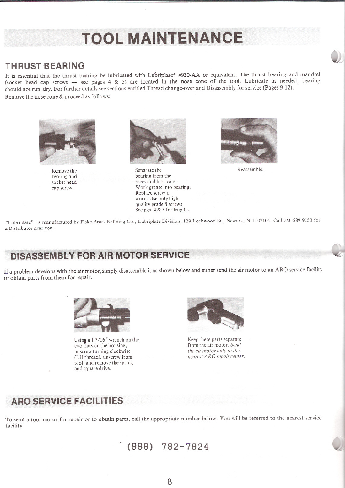
TOOL MAINTENANCE
THRUST BEARING
It is essential that the thrust bearing be lubricated with Luoriplate* #930-AA or equivalent. The thrust bearing and mandrel
(socket head cap screws - see pages 4 &5) are located in the nose cone of the tool. Lubricate as needed, bearing
should not run dry. For further details see sections entitled Thread change-over and Disassembly for service (Pages 9-12).
Remove the nose cone &proceed as follows:
Remove the
bearing and
socket head
cap screw.
Separate the
bearing from the
races and lubricate.
Work grease into bearing.
Replace screw if
worn. Use only high
quality grade 8 screws.
See pgs. 4 &5 for lengths.
Reassemble.
*Lubriplate® is manufactured by Fiske Bros. Refining Co., Lubriplate Division, 129 Lockwood St., Newark, N.J. 07105. Call 973 -589-9150 for
a Distributor near you.
DISASSEMBLY FOR AIR MOTOR SERVICE
If a problem develops with the air motor, simply disassemble it as shown below and either send the air motor to an ARO service facility
or obtain parts from them for repair.
U sing a 1 7/16" wrench on the
two flats on the housing,
unscrew turning clockwise
(LH thread), unscrew from
tool, and remove the spring
and square drive.
ARO SERVICE FACILITIES
Keep these parts separate
from the air motor. Send
the air motor only to the
nearest ARO repair center.
To send a tool motor for repair or to obtain parts, call the appropriate number below. You will be referred to the nearest service
facility.
(888) 782-7824
8
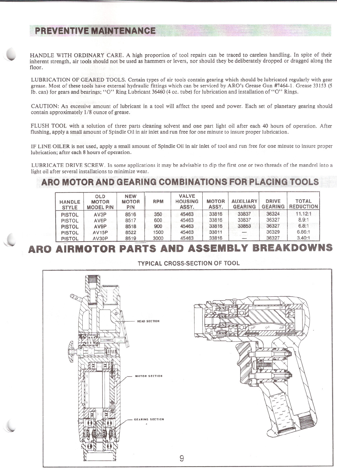
PREVENTIVE MA~~TENANCE
HANDLE WITH ORDINARY CARE. A high proportion of tool repairs can be traced to careless handling. In spite of their
inherent strength, air tools should not be used as hammers or levers, nor should they be deliberately dropped or dragged along the
floor.
LUBRICA nON OF GEARED TOOLS. Certain types of air tools contain gearing which should be lubricated regularly with gear
grease. Most of these tools have external hydraulic fittings which can be serviced by ARO's Grease Gun #7464-1. Grease 33153 (5
lb. can) for gears and bearings; "0"Ring Lubricant 36460(4oz. tube) for lubrication and installation of "0"Rings.
CAUTION: An excessive amount of lubricant in a tbol will affect the speed and power. Each set of planetary gearing should
contain approximately 1/8 ounce of grease.
FLUSH TOOL with a solution of three parts cleaning solvent and one part light oil after each 40 hours of operation. After
flushing, apply a small amount of Spindle Oil in air inlet and run free for one minute to insure proper lubrication.
IF LINE OILER is not used, apply a small amount of Spindle Oil in air inlet of tool and run free for one minute to insure proper
lubrication; after each 8 hours of operation.
LUBRICATE DRIVE SCREW. In some applications it may be advisable to dip the first one or two threads of the mandrel into a
light oil after several installations to minimize wear.
ARO MOTOR AND GEARING COMBINATIONS FOR PLACING TOOLS
OLD
NEW VALVE
HANDLE MOTOR
MOTOR
RPMHOUSINGMOTORAUXILIARYDRIVETOTAL
STYLE MODEL PIN
PIN ASSY.ASSY.
GEARING
GEARINGREDUCTION
PISTOL
AV3P85163504546333816338373632411.12:1
PISTOL AV6P8517600454633381633837363278.9:1
PISTOL
AV9P8518
i
900 45463338163385336327
6.8:1
IPISTOL AV15P
8522
1500
4546333811
-
36329
6.86:1
PISTOL AV30P851930004546333816
-
36327
3.40:1
ARO AIRMOTOR PARTS AND ASSEMBLY BREAKDOWNS
TYPICAL CROSS·SECTION OF TOOL
HEAD SECTION
MOTOR SECTION
GEARING SECTION
9

GEARING SECTION
DRIVE GEARING
DISASSEMBL Y
a. Remove Spindle and components from Ring Gear.
b. To remove Gears from Spindle, remove Bearing,
Spacer and Shafts.
REASSEMBLY
NOTE: Pack bearings and lubricate gears liberally with
33153 grease or equivalent upon assembly. Gearing
assembly should contain approx. 1/8 Ol. grease.
32325 BEllRING\
36325 RING GEAR -, \
30901 [)RIVE GEAR ~
(9INT-17EXT.TEETH) . ~
32325 BEARING\ ~
36325 RING GEAR -, \ . ~ "7...,
\ a~}
~
33691 SPACER
3OB99 GEAR (21~i.
(12TEETHi ~
a. Assemble Spacer (33691) or (33693) and Gears to
Spindle and secure with Shafts, aligning notch in
Shafts with Spacer. NOTE: Shafts (33686) contain
fifteen (15) loose Needle Bearings (33458) per shaft.
b. Assemble Spacer (37676), where applicable, and
Bearings to Spindle and assemble to Ring Gear.
- 32325 BEARING
36324 GEARING ASS'Y
5.56'1
,
~33436 SHAFT(2l
,37676 !;Pjl,CER (32325 BEARING
I~
36327 GEARING ASS'Y
3.4 I
I
\ ~ 33686 SKAFT(21'--()It:::l (INCLUDES LOOSE NEEDLE BEARINGS
] ~ PE R SHAFT)
REPLACE WITH 33686 KIT
36325 RING GEAR
32325 BEARING~ \\\.
'33438 GEAR (2)
(17 TEETH)
~~-A
r-.
I!32325 BEARING
./
.~)1--(0-36329 GEARING ASS"
J. .6660 \ \~VJA)6.861~ ~
10

AUXILIARY GEARING
Y147-7 RETAINING RING-,
{37676 SPACER
, ;- 32325 BEARING
/32325 BEARING
•~"
/ ~ /'0, \
\, \ '- ~ ;' 33837 GEARING ASS'Y
~ ~561
MOTOR SECTION
DISASSEMBL Y aligning air inlet holes of Cylinder with air inlet slots
a. Remove Motor from Housing. Grasp Cylinder in of End Plate and assemble Blades into Rotor Slots.
one hand and tap splined end of Rotor with a non- d. Assemble front End Plate (31602) to Rotor and Cylin-
metallic hammer; motor will come apart. der, aligning Roll Pin in Cylinder with hole in End
REASSEMBLY Plate.
a. Pack bearings with grease (33153), or equivalent, e. Insure Rotor does not bind (if Rotor binds, lightly
and coat I.D. of cylinder with spindle oil upon tap splined end with a non-metallic hammer to
assembly. loosen) and assemble motor to housing with Locating
b. Assemble Bearings into End Plates and assemble Pin (32814) and Porting Block (45471).
rear End Plate (3160 1)to Rotor. f. Assemble Spacer (32310), Spacer (32305) and gear-
c, Assemble Cylinder over Rotor to rear End Plate ing to tool.
33816
----
MOTOR
ASSEMBLY
33811
MOTOR
ASSEMBLY
Y65-7 BEARING
END PLATE
Y65-7 BEARING
~65-15 BEARING
,31602 END PLATE
36806 HOUSING *r
(LEVER THROTTLE ONLY) I
JI"<TO' GRI' ON' VJ
';
SPACER 32310 *"
SPACER 32305 *" ' -
*NOT INCLUJED IN MOTOR ASS'Y. ~
flNCLUDED WITH CYLINDER ~ fROLL PIN Y178-20
f ROLL PIN Y178'24
LOCATING PIN 32814 *
(PISTOL GRI P ONLY)
11

~ 42911 SCREEN (2}A
~ Yl47-68 "ET tr))
". AINING RING-----/~
M30
32
/~
; ,
..
\ i
"~~---_\;
==::t}o
45462 HOUSING ASS'y,
INClUOES 35967 GREASE FITTING.
NOr SHOW N
ings (45465).
b Assemble "0" rin.9 (Y325-7) to valve assembly (47880)
c Lubricate plunger (47879) and valve assembly (47880) with
ARO 29665 spindle all
d. Assemble springs (48806-1) to valve assembly (47880).
e Assemble plungers (47879) and valve assemblies (47880) to
bushings (45465) and assemble bushings to housing, align-
ing flats of bushings with flats of shroud
f. Assemble shroud (45468) to housing, securing with screw
(Y222-] 56-C)
g Assemble trigger to Shroud, secUring With roll pm (Y178-25)
h' Assemble muffler (45474) and screens (42911) to hOUSing,
securing with retaining ring (Y147-68)
DISASSEMBl Y
--------- HEAD SECTION ---------
45474
~
47880 VALVE ASSEM8l Y (2)
f81 YJ25-7 "0" RING (2)
.45471 PORTING 9LO;::K~
REASSEMBLY
45469 TRIGGER
a Remove roll pm (Y178-25), releasing trigger (45469)
b Remove screw (Y222-156-C), releasing shroud (45468)
cGrasp end of valveassembly (47880) and pull to remove valve
assembly and bushing (45465)
d Removeretaining f1ng(Y147-68). reieasing screens (42911) and
muffler (45474)
NOTE Whenever a port containing "0" rings has been removed
from loot, It is recommended the '0' rings be replaced Grease
all '0' rings before assembly.
c Assemble "0" rings (Y325-13, Y325-12 and Y325-11) to bush-
*NOT INCLUDED IN
45463 HOUSING aVALVES ASS'Y REVERSIBLE
45463 HOUSING 8 VALVES ASS'Y
PARTS MARKED THUS ~ ARE INCLUDED IN SERVICE KIT NO. 42122-2, SEE PAGE ]0,
12

HEAD SECTION
LEVER HEAD
DISASSEMBL Y
a. Remove Nut (36609) and Valve Parts may be re-
moved from Head.
b. To remove Reversing Valve (39207), remove Roll
Pin (YI78-7).
Motor assemblies for Lever Throttle tools: with
Motor Housing removed from Head; place Head in a
suitable holding device with the motor end in an up-
right position. Place Motor assembly on Head align-
ing Roll Pih (Y 178-24) with hole in Head. Slip Motor
Housing over Motor and secure to Head.
Assemble Spacers (32310), (32305) and Gearing to
tool.
REASSEMBLY
a. Assemble "0" Ring (YI25-2) to Valve Stem (3
and assemble to Head.
b. Assemble Spring (31131), Regulator (35642)
Seal (35675) to Head and secure with Nut (366C
*NOT INCLUDED IN HEAD ASS'Y
<~EETABLE)
"36992 ",VET 1o·
I
32863 BAIL*
~MUFFLER*
.~ I(([:j®)
~178-~ I ~.----' ,,::::\
ROLL PIN f
I39209 HOUSING130032 SPR ING 36602 VALVE STEM
~ Y125-2 "0"
~ RING
__ - 311" SP",NG
~ 35642 AIR REGULATOR
~~ 35675 SEAL
I /~- 73262 NYLON BALL
39210 HEAD ASS'Y .-- 36609 NUT
4/14/08
AVK INDUSTRIAL ,PRODUCTS
n!'t!J"'j
Ari;ri,;Company
25323 RYE CANYON ROAD • VALENCIA, CALIFORNIA 91355-1271
TELEPHONE: (661) 257-2329 FAX: (661) 257-8043
VISIT AVK'S WEBSITE AT AVKFASTENERS.COM CAT.NO 213M REV.l
This manual suits for next models
5
Table of contents
Other PCC Tools manuals


