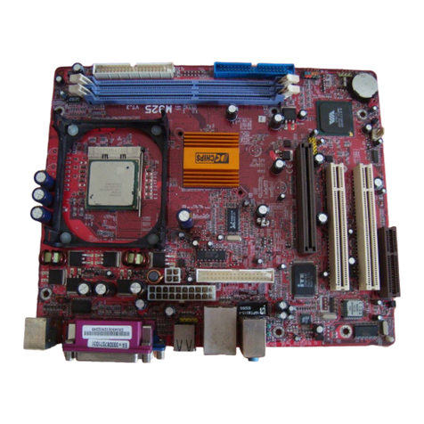
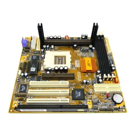
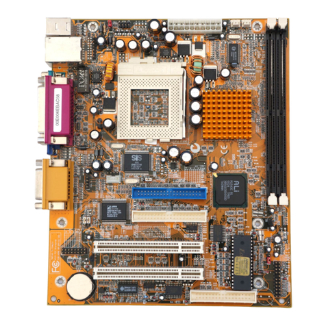
PCchips M748LMRT User manual

This publication, including all photographs, illustrations and
software, is protected under international copyright laws, with all
rights reserved. Neither this manual, nor any of the material
contained herein, may be reproduced without the express written
consent of the manufacturer.
The information in this document is subject to change without
notice. The manufacturer makes no representations or warranties
with respect to the contents hereof and specifically disclaims any
implied warranties of merchantability or fitness for any particular
purpose. Further, the manufacturer reserves the right to revise this
publication and to make changes from time to time in the content
hereof without obligation of the manufacturer to notify any person
of such revision or changes.
Trademarks
I M, VGA, OS/2, and PS/2 are registered trademarks of
International usiness Machines.
Intel, Pentium, Pentium-II, MMX, and Celeron are registered
trademarks of Intel Corporation.
Microsoft, MS-DOS and Windows 95/98/NT are registered
trademarks of Microsoft Corporation.
Sound laster and S -Link are trademarks of Creative Technology
Ltd.
PC-cillin and ChipAway Virus are trademarks of Trend Micro Inc.
AMI is a trademark of American Megatrends Inc.
A3D is a registered trademark of Aureal Inc.
Other names used in this publication may be trademarks and are
acknowledged.
Copyright © 1999
All Rights Reserved
M748LMRT, Version 1.3
6T/April 1999

Federal Communications Commission (FCC)
This equipment has been tested and found to comply with the limits for a
Class digital device, pursuant to Part 15 of the FCC Rules. These limits
are designed to provide reasonable protection against harmful interference
in a residential installation. This equipment generates, uses, and can
radiate radio frequency energy and, if not installed and used in
accordance with the instructions, may cause harmful interference to radio
communications. However there is no guarantee that interference will not
occur in a particular installation. If this equipment does cause harmful
interference to radio or television reception, which can be determined by
turning the equipment off and on, the user is encouraged to try to correct
the interference by one or more of the following measures:
Reorient or relocate the receiving antenna.
Increase the separation between the equipment and the receiver.
Connect the equipment onto an outlet on a circuit different from that
to which the receiver is connected.
Consult the dealer or an experienced radio/TV technician for help.
Shielded interconnect cables and shielded AC power cable must be
employed with this equipment to insure compliance with the pertinent RF
emission limits governing this device. Changes or modifications not
expressly approved by the system’s manufacturer could void the user’s
authority to operate the equipment.
Declaration of Conformity
This device complies with part 15 of the FCC rules. Operation is subject
to the following conditions:
This device may not cause harmful interference, and
This device must accept any interference received, including
interference that may cause undesired operation.
Canadian Department of Communications
This class digital apparatus meets all requirements of the Canadian
Interference-causing Equipment Regulations.
Cet appareil numérique de la classe respecte toutes les exigences du
Réglement sur le matériel brouilieur du Canada.

Table of Contents
Chapter 1 Introduction..........................................................1
Key Features......................................................................................2
Slot-1 Processor Support...............................................................2
Socket-370 Processor Support.......................................................2
Memory Support............................................................................2
Expansion Slots.............................................................................2
On oard IDE channels...................................................................2
Power Supply and Power Management.........................................2
Built-in Graphics System...............................................................3
Sound System................................................................................3
On oard I/O Ports..........................................................................3
Hardware Monitoring....................................................................4
Built-in LAN Adapter....................................................................4
Fax/modem DAA Module.............................................................4
On oard Flash ROM.....................................................................4
Bundled Software..........................................................................4
Dimensions....................................................................................5
Package Contents...............................................................................5
Optional Accessories.....................................................................5
Static Electricity Precautions.............................................................6
Chapter 2 Mainboard Installation.........................................7
Main oard Components.....................................................................8
Install the Processor...........................................................................9
Installing a Slot-1 Processor Cartridge........................................10
Installing a Socket-370 Processor................................................11
Install Memory.................................................................................12
Set the Jumpers................................................................................13
Jumper JP1: Key oard Power On Selector..................................14
Jumper JP5: Clear CMOS Memory.............................................14
Jumper JP4: Ena le/Disa le On oard Audio..............................14
Jumper JP3: Ena le/Disa le On oard LAN................................15
Jumper JP9: Ena le/Disa le On oard Fax/modem.....................15
Jumper JP7: Select Slot-1 or Socket-370 Processor....................15
Install the Main oard.......................................................................16
Install the Extension Brackets..........................................................18
Audio Ports and Game/MIDI Port Extension Bracket................18
Serial/Parallel Ports Extension Bracket.......................................19
LAN Adapter Extension Bracket.................................................20

Table of Contents
Fax/modem DAA Module...........................................................20
VGA Extension Card...................................................................21
Optional Extension Brackets............................................................22
ATX Form Card...........................................................................22
Digital Audio Extension Bracket.................................................23
Install Other Devices........................................................................24
Floppy Disk Drive.......................................................................24
IDE Devices.................................................................................24
Internal Sound Connections.........................................................25
Digital Audio Connection............................................................25
Expansion Slots................................................................................26
LAN Wake Up.............................................................................26
Chapter 3 BIOS Setup..........................................................27
Introduction......................................................................................27
Running the Setup Utility................................................................28
Standard CMOS Setup Page............................................................29
Advanced Setup Page......................................................................30
Power Management Setup Page.......................................................32
PCI / Plug and Play Setup Page.......................................................33
Load Optimal Settings.....................................................................34
Load Best Performance Settings......................................................34
Features Setup Page.........................................................................35
CPU PnP Setup Page.......................................................................36
Hardware Monitor Page...................................................................37
Change Password.............................................................................38
Change or Remove the Password................................................38
Exit...................................................................................................38
Chapter 4 Software & pplications.....................................39
Introduction......................................................................................39
Bus Master IDE Driver................................................................39
USB Driver..................................................................................39
Sound Driver................................................................................40
Graphics Drivers and Software....................................................40
Fax/Modem Drivers and Software..............................................40
Network Adapter Driver..............................................................40
BIOS Update Utility....................................................................40
PC-Cillin Software......................................................................40
ADCM Software..........................................................................41
Using the PCI Sound Application....................................................41
The Four Speakers System...............................................................42
Speaker Installation.....................................................................42


Error! No text of specified style in document.
Speaker Position..........................................................................42
Mixer Setup.................................................................................42
Demo...........................................................................................43
Table of contents
Other PCchips Motherboard manuals

PCchips
PCchips M726MRT User manual

PCchips
PCchips M935ALU User manual

PCchips
PCchips M754 Plus Series User manual

PCchips
PCchips M927 Series User manual

PCchips
PCchips Motherboard User manual

PCchips
PCchips A16 User manual

PCchips
PCchips M922LR V1.1 User manual

PCchips
PCchips M750 User manual

PCchips
PCchips M810LMR User manual

PCchips
PCchips M811LU User manual

PCchips
PCchips M770LMRT User manual

PCchips
PCchips M925ALU User manual

PCchips
PCchips M766LMRT User manual

PCchips
PCchips M728 User manual

PCchips
PCchips M938 Series User manual

PCchips
PCchips P51G Series User manual

PCchips
PCchips A11G User manual

PCchips
PCchips K7S5A User manual

PCchips
PCchips M851AG User manual

PCchips
PCchips M930 Series User manual