PCE Americas PCE-RT 10 User manual

MANUAL
SURFACE ROUGHNESS TESTER
PCE-RT 10
This Surface Roughness Tester is small in
size, light in weight, easy to carry. Although
complex and advanced, it is convenient to
use and operate. Its ruggedness will allow
many years of use if proper operating
techniques are followed. Please read the
following instructions carefully and always
PCE Americas Inc.
711 Commerce Way
Suite 8
Jupiter
FL-33458
USA
From outside US: +1
Tel: (561) 320-9162
Fax: (561) 320-9176
www.pce-instruments.com/english
www.pce-instruments.com
PCE Instruments UK Ltd.
Units 12/13
Southpoint Business Park
Ensign way
Hampshire / Southampton
United Kingdom, SO31 4RF
From outside UK: +44
Tel: (0) 2380 98703 0
Fax: (0) 2380 98703 9

TABLE OF CONTENTS
1. FEATURES....................................................1
2. SPECIFICATIONS..........................................2
3. FRONT PANEL DESCRIPTIONS AND
NAMES OF EACH PARTS...............................4
4. MEASURING PROCEDURE............................ 5
5. HOW TO SET THE EVALUATION LENGTH........7
6. HOW TO CALIBRATE THE TESTER................. 8
7.COMMUNICATE WITH PC................................8
8.GENERAL MAINTENANCE.............................. 8
9.REFERENCES............................................... 9
10.BATTERY REPLACEMENT ...........................10

1. FEATURES
This instrument is compatible with four standards
of ISO, DIN, ANSI and JIS and is widely used in
production site to measure surface roughness of
various machinery-processed parts, calculate
corresponding parameters according to selected
measuring conditions and clearly display all
measurement parameters. When measuring the
roughness of a surface, the sensor is placed on
the surface and then uniformly slides along the
surface by driving the mechanism inside the
tester. The sensor gets the surface roughness by
the sharp built-in probe. This roughness causes
displacement of the probe which results in change
of inductive amount of induction coils so as to
generate analogue signal, which is in proportion
to the surface roughness at output end of phase-
sensitive rectifier. The exclusive DSP processes
and calculates and then outputs the measurement
results on LCD.
* Multiple parameter measurement: Ra, Rz
* Highly sophisticated inductance sensor.
* Small in size, light in weight and easy to use.
* Can communicate with PC computer for
statistics, printing and analysing by the optional
cable and the software for RS232C interface.
*Manual or automatic shut down. The tester can
be switched off by pressing the Power key at any
time. On the other hand, the tester will power.
1
1
CAL
Ra/Rz Um/Uin
8
Itself off about 5 minutes after the last key
operation.
*Metric /Imperial Conversion
2. SPECIFICATIONS
Display: 4 digits, 10mm LCD, with blue backlight
Parameters: Ra, Rz
Display Range
Ra: 0.05-10.00um
Rz: 0.1-50.0um
Accuracy: Not more than ±15%
Fluctuation of display value: Not more than 10%
Sensor :
Test Principle: Inductance type
Radius of Probe Pin: 10µm
Material of Probe Pin: Diamond
Measurement Force of Probe: 16mN(1.6gf)
Probe Angle: 90°
Vertical Radius of Guiding Head: 48mm
Maximum driving stroke: 12.5mm/0.5inch
Cutoff length : 0.25mm / 0.8mm / 2.5mm optional
Driving speed:
sampling length = 0.25mm Vt=0.135mm/s
sampling length = 0.8mm Vt=0.5mm/s
sampling length = 2.5mm Vt=1mm/s
returning Vt=1mm/s
Resolution : 0.001um if reading<10um
0.01um if 10um≤reading<100um
0.1um if reading ≥100um
2

Evaluation length: 1~2 cut off optional
Power battery: 4x1.5vAA/UM 3
Operating conditions: Temp. 0~40℃
Humidity <80%
Size:128×80×30mm
Weight: about 280 g
Standard Accessories:
Carrying case
Main unit
Standard sensor
Standard sample plate
Operation manual
Screwdriver
Optional Accessories
Cable & software for RS232C
3
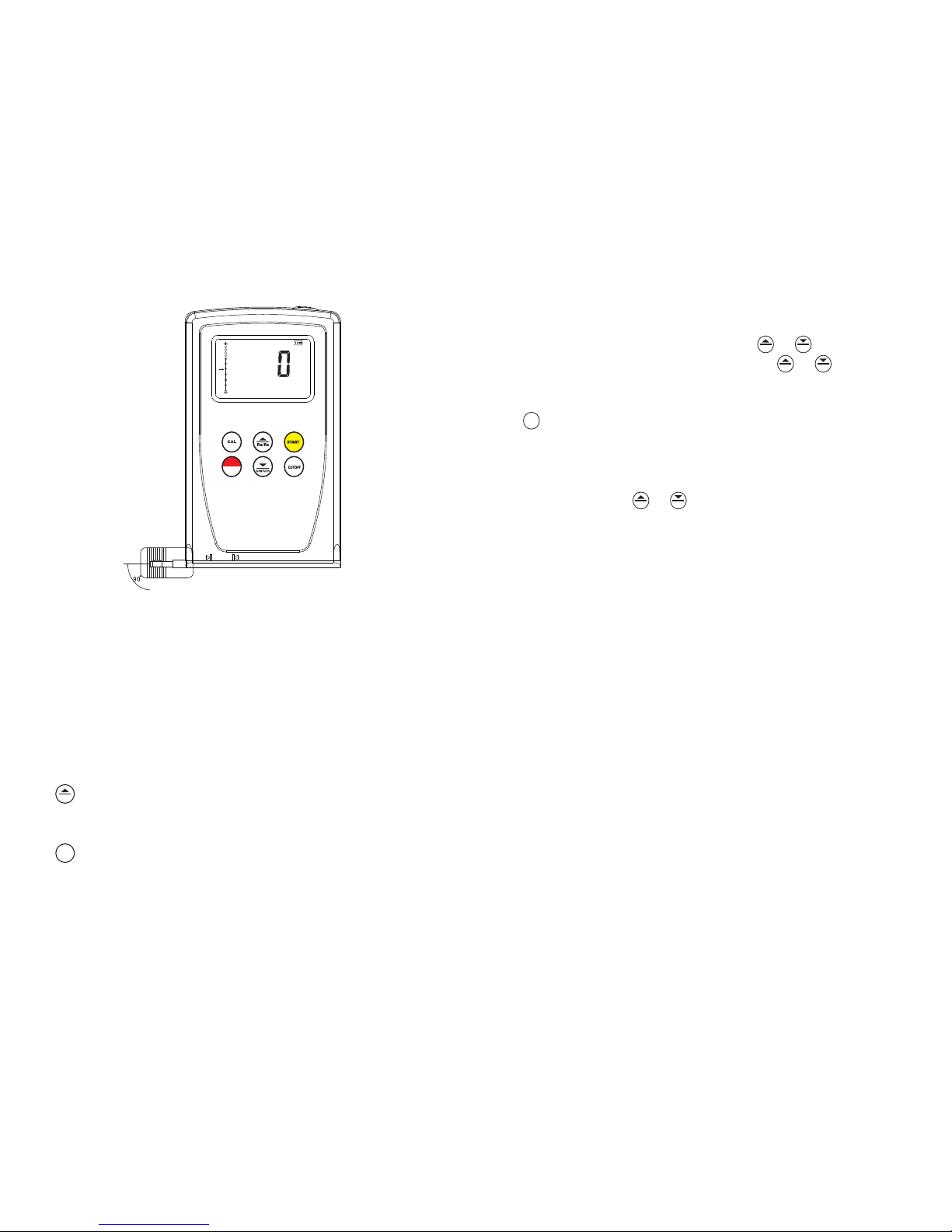
3. FRONT PANEL DESCRIPTIONS AND NAMES
OF EACH PARTS
3-8
3-10
3-9
Fig. 3-1
3-11
3-12
3-13
3-11
SURFACE ROUGHNESS TESTER
um
0.25mm
0
a
R
3-1
3-2
3-3
3-4
3-5
3-6
3-7
CAL
4

4. MEASURING PROCEDURES
4.1 Preparations for measurement
A. Switch on to test if the battery voltage is normal.
B. The instrument automatically restores conditions
of the last measurement before it is turned off since
these conditions are automatically stored. Before
taking measurement, preparations have to be made
and checked.
C. To check if the parameter selected is right. If not,
depress the key to select.
3-1
3-2
3-3
3-4
3-5
3-6
3-7
3-8
3-9
3-10
3-11
3-12
3-13
Calibration
Measurement
Position pointer
Parameters
Parameter Key & Up Key
CAL Key
Power Key
Battery
Unit
Cutoff
Start Key
Cutoff Key
um/uinch Key & Down Key
Ra/Rz
5
6
CUTOFF
Fig.4-1
D. To check if the cutoff length selected is right. if not,
depress the key to select. For the recommended
cut-off length, please see the table in 10.7on
page 13.
E. To check if the measurement unit selected is
right. If not, just press the key to switch between
the metric system and the British system.
F. To clear the surface of the part to be measured.
G. Refer to Figure 4-1 and Figure 4-2 to place the
instrument correctly, stably and reliably on the
surface to be measured.
H. Refer to Figure 4-2, the sliding trail of the
sensor must be vertical to the direction of process
line of the measured surface.
I. Adjustable leg and sheath of sensor
Um/Uin
7
Fig.4-2
4.2 Measuring
After preparations is done, just press Start key to
measureIf measuring conditions are not to be changed.
Firstly,you will see the “—” on the display and the probe
ismoving forward and sampling. Then you will see the
probe stop sliding and move backward. The
measurement result shows on the display after the
probe stop moving. You can browse measurement
values of different parameters once depressing the key
.
5. HOW TO SET THE EVALUATION LENGTH
To set or browse the evaluation length, just depress the
key and not release it until showing on the 'LEN'
display. It takes about 6 seconds from starting pressing
.
Ra/Rz
CAL
SURFACE ROUGHNESS TESTER
um
0.25mm
0
a
R
CAL
the key CAL. Then change the evaluationlength to the
desired length among 1~2Lby the key or . To save
or quit, just press any key except the key or .
6.HOW TO CALIBRATE THE TESTER
6.1 To enter the calibration state, just depressing the
key , The calibration state is marked by CAL“ ”.
6.2Take a measurement based on the Standard sample.
Contrast the measuring value with the value of standard
sample plate based on the same parameter.
6.3Depress the key or to adjust the reading to the
standard value.
6.4Just repeat 6.2 to 6.3 till the accuracy is ok.
6.5To quit, just press any key other than “START” key.
6.6 The instrument has been thoroughly tested before
delivery to ensure that the display value error is less
than 10%. The user is recommended not to use the
calibration function too often.
7. COMMUNICATE WITH PC
This tester can communicate with PC computer by use
of the optional communicating cable and software. For
detailed information, please see the instructions with
the optional software.
8. GENERAL MAINTENANCE
8.1 Avoid crashes, intensive vibration, heavy dust,
humidity, grease stains and strong magnetic fields.
8.2 The sensor is a precise part and should be protected
carefully. It is recommended to put it back in the box
after each operation.
8.3 Protect the standard sample plate belonging to the
instrument carefully to avoid calibration faults caused
Ra/Rz Um/Uin
Ra/Rz Um/Uin
CAL
Ra/Rz Um/Uin
8
by scratches.
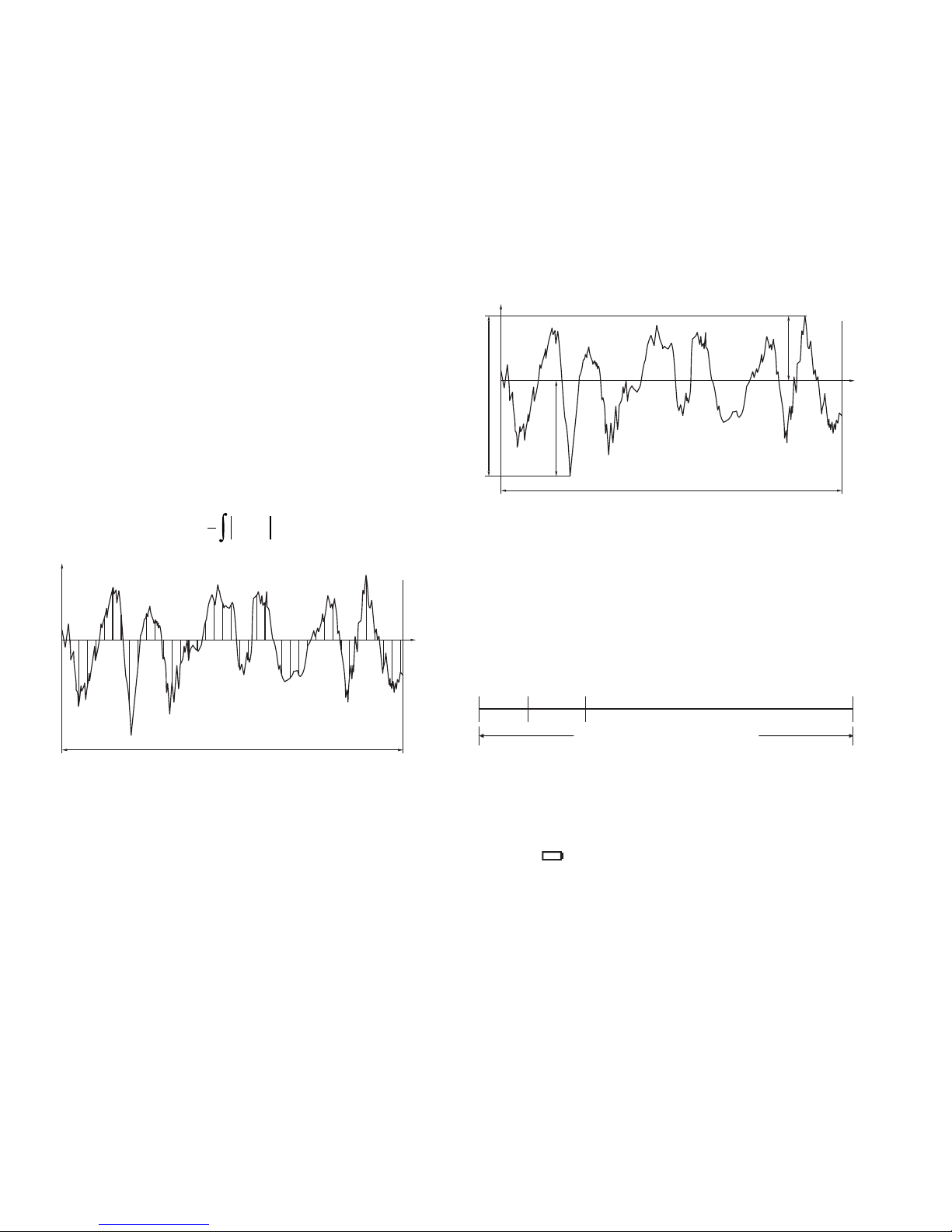
9. REFERENCES
9.1 Central line
This tester adopts minimum central line of Least
Square Algorithm.
9.2 Definition of roughness parameter
9.2.1 Ra arithmetical mean deviation of profile
Arithmetic value of mean deviation of profile
within sampling length.
9.2.2 Rz maximum height of profile
Sum of height of the largest profile peak height
Ypmax and the largest profile valley depth Yvmax
within a sampling length.
9
Sampling Length(l)
Y(x)
x
( ) dxxY
l
Ra
l
=
0
1
10. BATTERY REPLACEMENT
10.1 When it is necessary to replace the battery,
i.e battery voltage less then approx 5v, the battery
symbol ‘ ’ will appear on the Display.
10.2 Slide the Battery cover(3-6)away
from the instrument and remove the
ll
Traversing length
l×n
Approach
length
Pre-travel
length
Evaluation length
Origin Normal measuring
position
9.3 Code Standard Name
ISO 4287 International Standard
DIN 4768(2010-07-00) German Standard
JIS B601 Japanese Industrial Standard
ANSI B46.1 American Standard
9.4 Traversing length
L=sampling length
n=number of sampling length
l x n=evaluation length
10

Cutoff length
(mm)
batteries.
10.3 Install the batteries (4x1.5v AA/UM 3)
correctly into the case.
Cutoff length recommended
Please see the table on page 13.
>0.63~0.8
>0.5~0.63
>0.4~0.5
>0.32~0.4
>0.25~0.32
>0.2~0.25
>0.16~0.2
>0.125~0.16
>0.1~0.125
2.5
0.8
0.25
>0.63~1.25
>0.32~0.63
>0.25~0.32
Ra
(μm)
Rz
(μm)
>5~10
>2.5~5
>1.25~2.5
>0.20~0.25
>0.16~0.20
>0.125~0.16
>0.1~0.125
>0.08~0.1
>0.063~0.08
>0.05~0.063
>0.04~0.05
>0.032~0.04
>0.025~0.032
>0.02~0.025
>3.2~6.3
>1.6~3.2
>1.25~1.6
>20~40
>10~20
>6.3~10
>1.0~1.25
>0.8~1.0
11
Table of contents
Other PCE Americas Test Equipment manuals


