Cirris signature 1100R+ User manual

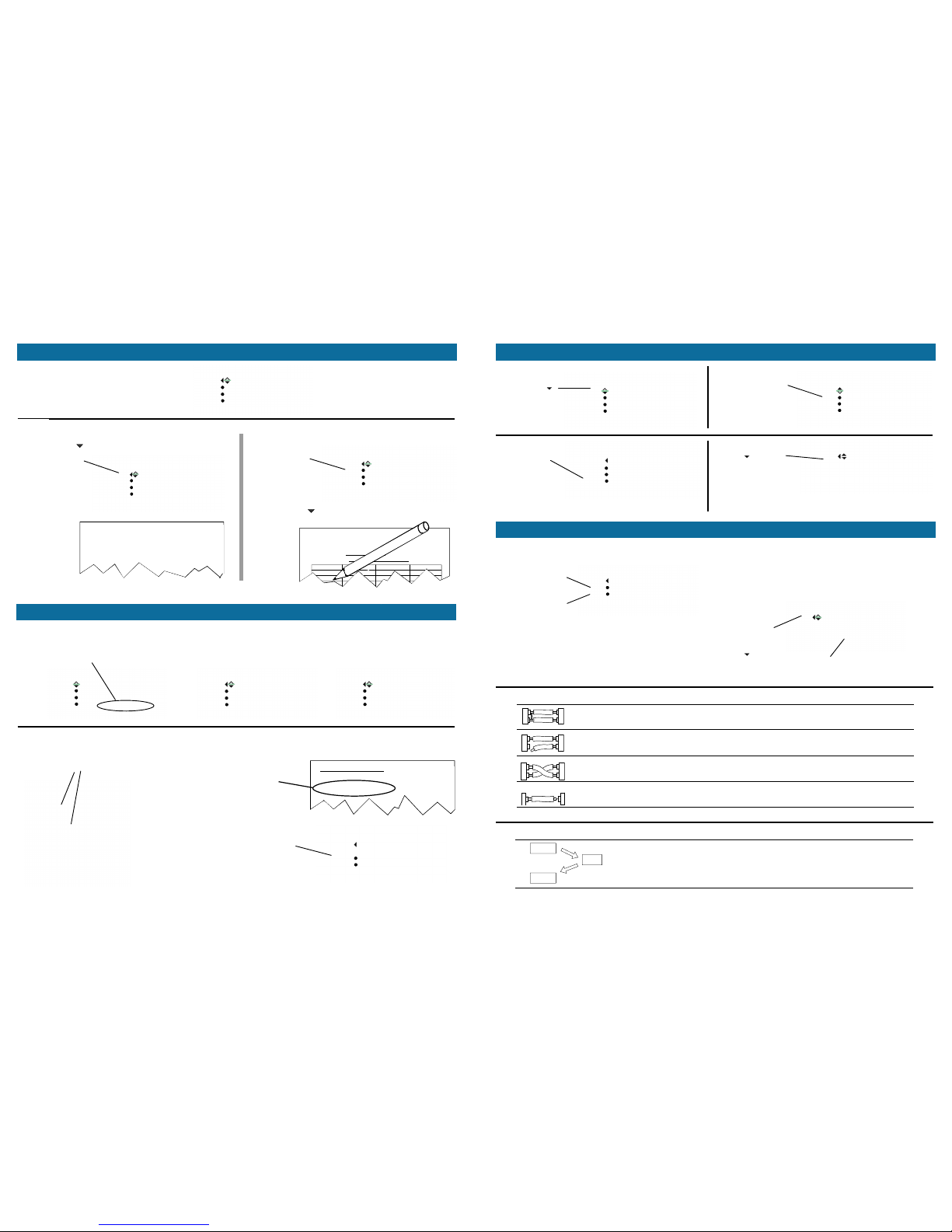
Bad Resistor
Bad Capacitor
The tester senses that the measured component is outside the 10%
tolerance programmed in the cable test.
Missing Resistor
Missing Capacitor
Missing Diode
The tester does not sense a component where it should be in the cable.
Leaky Diode The tester senses a greater than normal current flow through the diode’s
reverse bias.
Reversed Diode The senses a diode’s orientation is reversed.
Your 1100R+ Users Manual contains a more detailed explanation of this product. In addition a Cirris customer
support representative is always ready to assist you. For Customer Support in the USA call 1-800-441-9910.
Outside the USA locate the closest Cirris Sales Office by entering the URL www.cirris.com\contact.html.
Example of an error printout
J1-02 is open.
It should be connected
to J2-19.
Instead, J1-02 is
miswired to J2-02.
This shows that in net
#5 J1-05 is shorted to
J2-16
Since the cable has errors, the cable
signature will not match the signature in
the documentation. Instead, the tester
prompts an “Error Signature.”
-02 refers to pin #2 in
the connector.
J1 refers to the
position of the
adapter in the tester
This is the net
number, net #2.
CABLE ERROR SIGNATURE: EBF613-0706
2 J1-02
OPEN J2-19
MISWIRE J2-02
3 J1-03
OPEN J2-18
MISWIRE J2-02
4 J1-04
OPEN J2-17
MISWIRE J2-03
5 J1-05
SHORT J2-16
6 J1-06
OPEN J2-15
Cable/Harness testing made easy®
Getting More Help
Component Errors Quick Reference Guide
Basic Operation
Menu Title
Always on the top line in
capital letters.
Back Button
Returns to the
previous menu or
to the main menu.
Up/Down Buttons
Scroll menu options
and settings.
Selection Buttons
Select menu options.
Available Directional Buttons
Displayed on top line may include:
Top of list; more below
Scroll up or go back
STEP 1: Attach the cable to be learned.
2. Press Create New Test.*
3. Press LEARN.
1. Press Verify Test.*
2. Use the down button to check that the cable
signature, settings, and connections are correct.
Scroll either up or down
SIGNATURE 1100R+
Set User Preferences
Set Up Test Program
TEST: 1B4137-4Z20
2. Replace the
cover plate.
3. Connect a
sample cable.
STEP 2: Learn the sample cable.
STEP 3: Verify the learned cable is correct.
You’re ready to
save the learned
test in memory
For more information on saving and retrieving a cable in memory, see
the sections: Saving a Test to Memory and Retrieving a Test From
Memory.
*
If you have a connected printer, you may want to verify by printing.
For more information see the Documenting a Cable section.
*
During this process, you can change the learn settings for your cable
specifications. See Changing Setting for Learning and Testing.
*
start testing.
1. Install the correct adapters.
OR
1100R+
®
3. Use the back button to return to the CABLE
LEARNED menu.
SIGNATURE 1100R+
Set User Preferences
Set Up Test Program
TEST: 1B4137-4Z020
1. Press Set Up Test Program.
Creating a Test from a Cable
*
cover plate
Version 4.5d
CABLE LEARNED
Verify Test
Save Learned Test
TEST: 39E92F-4Z020
CABLE LEARNED
Verify Test
Save Learned Test
TEST: 39E92F-4Z020
Step 1: Create a test from a sample cable
as in the previous section.
2. Press Print.
If you have a printer connected: If you don’t have a printer connected:
Documenting a Cable
Step 2:
1. Press
Verify Test.
The document
is printed.
1. Press down
to view the print
option.
1100R+ Cable Documentation
Cable Signature: 39E92F−4Z020
Cable Description: Merrit Dialisis Power
Adapter Signature(s):
J1 03FAC1 J9 J17 J25
J2 B53FD7 J10 J18 J26
J3 J11 J19 J27
Step 1: Make sure the test program you want to use is loaded.
Creating a test from a cable.
1100R+ Cable Documentation
Cable Signature: 39E92F-42020
J1 Adapter Signature: F5B4E0
J2 Adapter Signature: 03FAC1
Connection Resistance: <Auto .5
Insulation Resistance: >50M
retrieving a test from memory.
OR
1100R+ Cable Report
Cable Signature: 39E92F-4Z020
J1 Adapter Signature: F5B4E0
J2 Adapter Signature: 03FAC1
Connection Resistance Threshold <= Auto .5
Insulation Resistance Threshold > 500K ohm
Testing a Cable
The loaded test is always displayed
on the main menu.
You can load a new test program by:
Step 2: Duplicate the adapter setup you had in the original test.
Refer to the documentation
you created for the test.
OR
1. Press Test for the loaded
test.
2. Press Show Required List.
3. After installing the correct
adapters, press RETRY to
check the setup.
To remember the correct adapter
positions in the tester:
Original adapter
positions
2. Scroll down , recording the information on a
1100R+ Cable Documentation Form.
creating a test from a cable
CABLE LEARNED
Verify Test
Save Learned Test
TEST: 39E92F-4Z020
CABLE LEARNED
Verify Test
Save Learned Test
TEST: 39E92F-4Z020
CABLE LEARNED
Verify Test
Save Learned Test
TEST: 39E92F-4Z020
SIGNATURE 1100H+
Set User Preferences
Set Up Test Program
TEST: 39E92F-4Z020
CABLE LEARNED
Verify Test
Save Learned Test
TEST: 39E92F-4Z020
TEST RETRIEVED
Print Test
Edit Retrieved Test
TEST: 39E92F-4Z020
INSTALL CORRECT
ADAPTERS TO TEST
Show Required List
RETRY
Step 1: From
the main menu
Scroll down .
Step 2: Press Do
File Management.
Whereas the cable’s connectors
and the wire pattern determine the
first part of the signature.
Interpreting Error Messages
Deleting a Test from Memory
SIGNATURE 1100R+
Set User Preferences
Set Up Test Program
TEST: 7EO1F7– 2J8NH
To See a Detailed Error Messages:
Step 3: Press
Delete a Test.
Step 4: Scroll
down to the
memory location.
Then press the
button for the
test to delete.
Low Voltage Errors
In this example we view
the first detailed error and
see NET 1 has a SHORT.
Press View Errors
OR
Press Print Errors
SHORT The tester senses an interconnection that should not exist in the cable.
OPEN The tester does not sense an interconnection that should exist in the cable.
MISWIRE The tester senses that a contact that should have a valid connection is
instead connected to a wrong contact.
HIGH
RESISTANCE
The tester senses a cable interconnection that has too much resistance.
Intermittent Errors
To be an Intermittent error the cable must be good, then go bad, then go
good again. Intermittent errors may be shorts, opens, miswires, and high
resistance — just like the Low Voltage errors above.
GOOD
BAD
GOOD
To see other
detailed errors,
we can scroll
down .
If Fault Location is ON, asterisks show
the short is closest to these two pins.
DO FILE MANAGEMENT
Print Mem Loc List
Save Current Test
Delete a Test
TEST TO DELETE
4: A39CB4-2J8NH
5: 8E10C4-2J8NH
6: B34892-6F8N0
SIGNATURE 1100R+
Do File Management
Version Information
PRINT: 7EO1F7– 2J8NH
FAILED LOW VOLTAGE
View Errors
Print Errors
Remove=> New Test
ERROR:BBF085-2X8NH
NET 1: SHORT
J1-001 *J3-001 TO
J1-002 *J3-002

Saving a Test to Memory
Step 1: After learning from a sample cable... or editing a test...
Step 2: Scroll to the desired memory location,
then press the button to save to that location.
If at any other time you need to save a test: (1) from the main menu, scroll down once, (2) press Do File Management, and then (3) press Save
Current Test.
Step 3: If desired, record the location of the test on
the Memory Location Listing for the tester.
Note: You can either select an empty location or overwrite an existing
cable test.
press the save option.
Step 1: From
the main menu
press Set Up
Test Program.
Step 2: Press
Load Test.
Step 3: Scroll
to the test’s
memory
location and
press the button
to retrieve it.
You may find the Memory Location Listing helpful to recall a cable test from
memory.
Mem.
Loc.
Cable
Description
Cable
Signature
1 EEC Lever Arm pn: 28−LV298 2833B6−6F8N0
2 Evans Air Simulator IV pn: 398793−4 3967B9−9G6BF
3 Evans Night Shield pn: 368494−3 F40963−9G6BF
4 Merrit Dialise Power Cable pn: 00560894 A39CB4−2J8NH
5 Merrit Display panel Cable pn: 00678904 8E
6 Dynonet add−on Cable pn E674−24 B34892−6F8N0
SIGNATURE 1100R+
Set User Preferences
Set Up Test Program
TEST: 7EO1F7– 2J8NH
Retrieving a Test from Memory
1100R+ Memory Location Listing
1100H+ Serial Number: 56832−11H
Mem.
Loc.
Part
Number
Cable
Description
Cable
Signature
1 28−LV298 EEC Lever Arm 2833B6−6F8N0
2 398793−4 Evans Air Simulator IV 3967B9−9G6BF
3 368494−3 Evans Night Shield F40963−9G6BF
4 00560894 Merrit Dialise Power Cable A39CB4−2J8NH
5 00678904 Merrit Display panel Cable 8E10C4−2J8NH
6 E674−24 Dynonet add−on Cable B34892−6F8N0
TEST EDITED
Print Test
Save Edited Test
TEST: 8E10C4-2J8NH
CABLE LEARNED
Verify Test
Save Learned Test
TEST: 8E10C4-2J8NH
SET UP TEST PROGRAM
Create New Test
Load Test
Edit: 7EO1F7– 2J8NH
SAVE: 7EO1F7–2J8NH
4:39CB4-2J8NH
5:
6: B34892-6F8N0
TEST TO LOAD
4: A39CB4-2J8NH
5: 8E10C4-2J8NH
6: B34892-6F8N0
If the cable passes: If the cable fails:
The screen displays
the type of error.
The red LED lights.
The tester sounds
Beep ...
The tester sounds
Tick Tick Tick ...
The green LED lights.
The screen displays,
PASSED ALL TESTS.
signifying the tester is
performing continuous
scans checking for
intermittent errors.
1 beep = opens
2 beep = short
3 beeps = miswire
FAILED: LOW VOLTAGE
View Errors
Print Errors
Remove => New Test
To get the detailed
error information
press View Errors or
Print Errors.
STEP 5: Remove the cable and connect the next one to the tester.
Step 3: Attach the cable to be tested and start the cable test.
When you remove the
cable the display tells
you to attach the next
cable.
1. Attach the cable
to be tested.
Note: If the User Preference Test Mode is set to CONTINUOUS the test will start auto-
matically. If Test Mode is set to SINGLE TEST, press START TEST to start the test.
2. If you haven’t already,
press Test for the
loaded test.
CABLE LEARNED
Verify Test
Save Learned Test
TEST: 39E92F-4Z020
PASSED ALL TESTS
Remove Cable
STOP TEST RUN
REPEAT HIPOT
CONTINUOUS TST MODE
Signature 39E92F-4Z020
** ATTACH CABLE **
Get Test Summary

To restore all Preferences and Settings to Factory Defaults:
To restore User Preferences and Learn settings.
1. From the main menu press Set User Preferences.
2. Scroll down once and press Set Factory Defaults.
3. Press RESET.
Changing User Preferences
User Preferences affect
the way the tester
performs and interacts
with the operator.
User Preferences do not
affect the critical charac-
teristics of the cable test.
To change the User Preferences:
1. Press Set User
Preferences.
SIGNATURE 1100R+
Set User Preferences
Set Up Test Program
TEST: 7EO1F7– 2J8NH
2. Use selection and arrow buttons to
change User Preferences.
Preference
Name
Description Factory
Default
Test Mode CONTINUOUS: Starts the cable test as soon
as a connection is sensed. At the end of the
cable test. the cable is scanned for intermit-
tents until removed .
SINGLE TEST: Tester waits to start the test
until the TEST is pressed.
CONTI-
NUOUS
Fault
Location
ON: The tester displays an asterisk next to
the pin(s) closest to an open, short or miswire.
OFF: No fault location information will be
displayed.
OFF
Auto Start ON: The tester will automatically start testing
using the loaded test.
OFF: Normal tester operation
OFF
Test
Count
ALL CABLES: The test summary includes
three counts: total cables tested, cables
tested good, and cables tested bad.
GOOD CABLES ONLY: The test summary
includes only the count for good cables.
ALL
CABLES
Auto Print ON: Allows you to select a report that will
automatically print while testing. Report for-
mats vary and will print after each cable,
passing cable, or failing cable.
OFF: Operator must press PRINT to print test
results.
OFF
Volume OFF, LOW, MEDIUM, HIGH: Allows you to
adjust the tester sound volume. See manual if
more volume is needed.
MEDIUM
Common User Preferences
Setting
Name
Description Factory
Default
Conn Res
(Connection
Resistance)
Cable connections must be lower than this
resistance to be learned and to pass the test.
10.0Ω
LV Insul
Res
(LV Insulation
Resistance)
Unintended connections are considered shorts
if under this resistance value. Also, intended
connections are considered opens as opposed
to having high resistance if over this resis-
tance.
100KΩ
Component
Resistance
Automatically set when learning components if
setting Learn Components is turned on. Com-
ponent are recognized as components if above
this setting value.
NONE
Learn
Compo-
nents
Only in learn settings. Allows the tester to
recognize passive components such as ca-
pacitors, diodes, and resistors.
OFF
To change the Learn Settings:
1. From the main menu press Set Up Test Program.
2. Press Create a New Test.
3. Press Set Learn Settings.
To change the Test Settings for the loaded test:
1. If the test you want to change is not loaded, make
it the loaded test by learning a sample cable or
retrieving a cable from memory.
2. From the main menu, press Set Up Test Program.
3. Press Edit XXXXXX-XXXXX.
Changing Settings for Learning and Testing
7E10F7-2J8NH
Learn/ Test Settings
Learn Settings affect how
a cable is learned.
After a cable is learned
these settings become the
Test Parameter Settings for
that cable.
Test Parameter
Settings affect how
a cable is tested.
The Test Parameter
Settings determine
the Parameter
Signature.
Remember, if editing a test program retrieved from
memory: The test program in a particular memory
location is not changed until the edited loaded test is
saved back to the test’s memory location.
Where XXXXXX-XXXXX is the
signature of the cable to edit.
Other manuals for signature 1100R+
1
Other Cirris Test Equipment manuals

Cirris
Cirris 4200 Series User manual

Cirris
Cirris CH2 User manual

Cirris
Cirris 4200 Series User manual

Cirris
Cirris easy-wire CR User manual

Cirris
Cirris CH2 User manual

Cirris
Cirris Touch1 LV Installation and operation manual

Cirris
Cirris CH2 User manual

Cirris
Cirris Easy-Touch Pro User manual

Cirris
Cirris CR User manual

Cirris
Cirris CH2 User manual

Cirris
Cirris CR User manual

Cirris
Cirris CH2 User manual

Cirris
Cirris CH2 User manual

Cirris
Cirris CH2 User manual

Cirris
Cirris Easy-Touch Pro User manual

Cirris
Cirris CH+ User manual

Cirris
Cirris 4200 Series User manual

Cirris
Cirris CR User manual

Cirris
Cirris Touch 1 User manual

Cirris
Cirris Touch1 LV Installation and operation manual


![OXO [T]Box RDM User instruction](/data/manuals/1q/n/1qnxm/sources/oxo-t-box-rdm-manual.jpg "OXO [T]Box RDM User instruction")