[EN] English - 3
K0405 Revision B
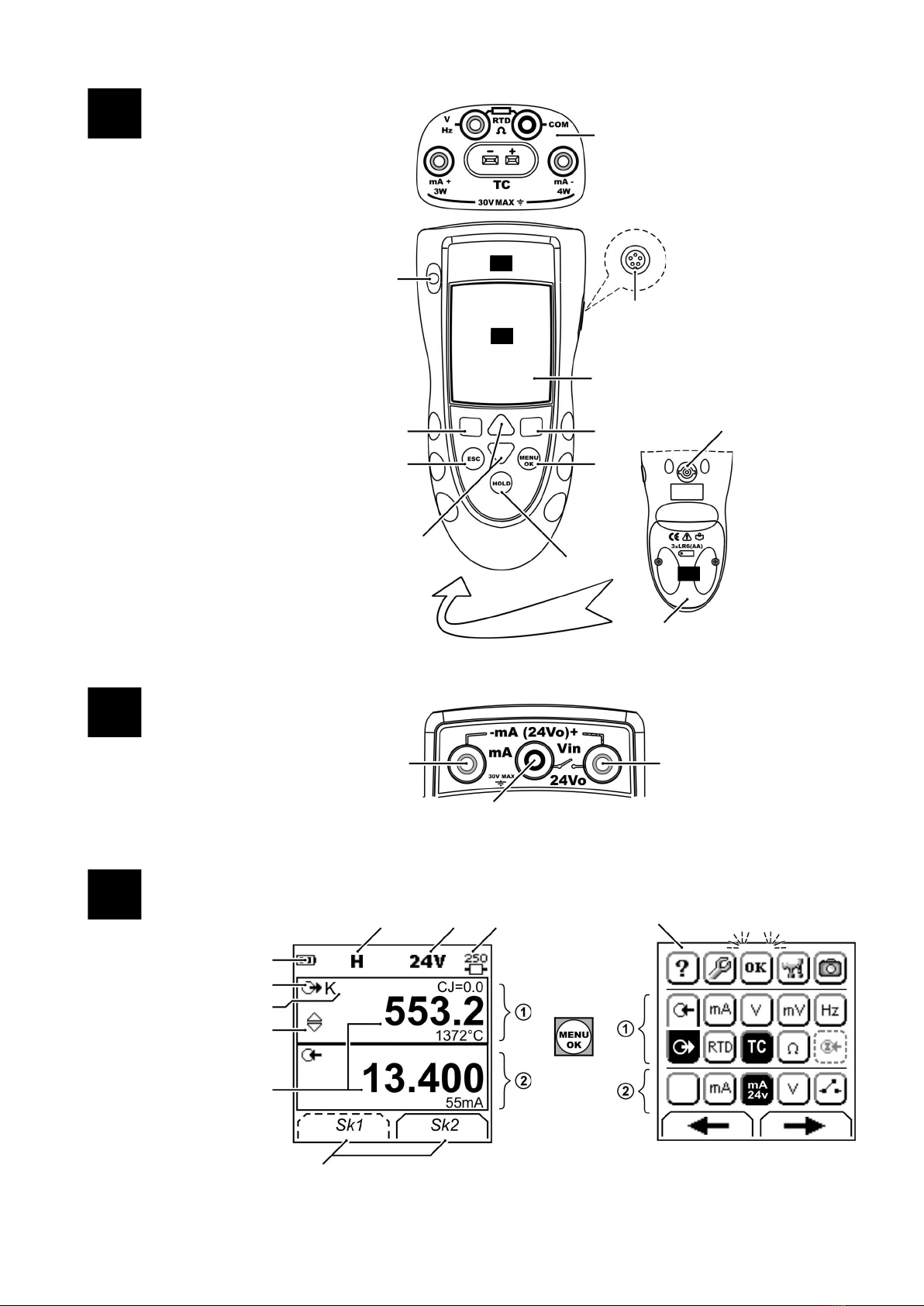
Key to figure A3 (Display)
Prepare the instrument
Before you use the instrument for the first time:
• Make sure that there is no damage to the instrument, and
that there are no missing items.
• Remove the plastic film that protects the display. Use the
tag ( ) in the top right-hand corner.
• Install the batteries (refer to B1). Then re-attach the cover.
Power on or off
To set the power on or off, press (A1 -item 1). The
instrument does a self test and then shows the applicable
data.
When the power is off, the last set of configuration options
stays in memory. Refer to “Maintenance”.
Set up the basic operation
Use the Set Up menu to set up the basic operation of the
instrument.
If there is additional data for a menu option, select
Settings () to see the values that are set up. If necessary,
adjust the values.
Table 1: Menu options - Set Up
Select a task (Measure and/or supply)
When the instrument is set up (Table 1), use the task
selection menu to select the applicable task.
If you attach a Universal Measurement Module (UMM) to the
communications port (A1 - item 9), the task selection menu
shows the applicable IDOS options.
Make the necessary selections from each area ( and ).
One task is permitted in each area.
Item Description
1. Task indication for the switch test.
= switch closed = switch open
UPM only. Task indication for the leak test.
There is a 250series resistor in the mA circuit.
Refer to: Table 2/3
2. The loop power supply is on.
Refer to: Table 2/3
3. The data on the display is on hold. To continue, press the
HOLD button again.
4. Shows the battery level: 0 to 100%.
5. Identifies the type of data.
= Input = Output
= IDOS input
Refer to: Table 2/3
21. to 22. The settings applied to the input or output:
6. K The thermocouple type (K, J, T ... ) - (Table 4/5).
CJ= ... The cold junction temperature (Table 1)
Pt... The RTD type (Pt50, ...) - (Table 4/5).
RTD input connections: 2, 3, or 4 (Figure 7)
5.0V ...V The input trigger level (Table 4) or the output
amplitude (Table 5).
7. , ... , = Output operation (Table 5)
8. 13.400
55mA
The measured values applicable to the task selections in
item 25, area and
+ the measurement range and units.
9. Sk1/2 A soft-key function. To select an available function, press
the soft-key below it. Example:
= Move left = Move right
10. The task selection menu. One task selection is permitted
in each area ( and ).
= cursor position (flashes on/off)
= a button or task selection is set in area or .
Sets the Dual Function, area selections to off. This
saves the battery power.
Refer to: Table 2/3
Help: Shows a connection diagram for the task
selections you have set.
Set Up: Shows the Set Up menu to set up the basic
operation. Refer to Table 1.
OK: Accepts the selections on the menu.
Note: MENU/OK also does this.
Utilities: Leak Test. Use this function with a UPM. Refer
to Figure 13.
Snapshot: Optional item - To use this facility, install the
data logging upgrade kit. Refer to the user manual -
K0397: DPI 800 series data logging upgrade kit.
1 2 Task selection
menu: 3Menu:
Set Up 4 5
+
(Table 2) (Table 1) []/[ ]
Options Description
... Scale To select the applicable international temperature
scale: IPTS 68 or ITS 90.
To add a 250 series resistor into the mA circuit. You
can then use this instrument together with a HART®
communicator to set up and calibrate HART® devices.
To select and set up the backlight facility + timer.
Additional data: Select Settings ( )
To select and set up the power off facility + timer.
Additional data: Select Settings ( )
To show the battery level (%).
To set the display contrast (%).
Increases %, decreases %
To set the time + date. The calibration facility uses the
date to give service and calibration messages.
To set the language option.
To calibrate the instrument.
Additional data: Refer to “Calibration”.
To select and show the applicable status data.
(Software Build, Calibration Due date, Serial Number,
IDOS Information).
1Task selection
menu: 2345
+
+
(Table 2/3) Task = mA output
Task selection
menu: 6Display:
mA output
(Table 2/3) Sk1 = Edit
Sk2 = Settings