PCE Health and Fitness PCE-HT 422 User manual

ENVIRONMENTAL DATALOGGER
PCE-HT 422
USER’S MANUAL
PCE Americas Inc.
1201 Jupiter Park Drive
Suite 8
Jupiter
FL-33458
USA
From outside US: +1
Tel: (561) 320-9162
Fax: (561) 320-9176
www.pce-instruments.com/english
www.pce-instruments.com
PCE Instruments UK Ltd.
Unit 11
Southpoint Business Park
Ensign way
Hampshire / Southampton
United Kingdom, SO31 4RF
From outside UK: +44
Tel: (0) 2380 98703 0
Fax: (0) 2380 98703 9

Contents
1. Application.......................................................................................................................................3
2. What is included...............................................................................................................................4
3. Basic requirements, operational safety.............................................................................................4
4. Fitting...............................................................................................................................................5
4.1. nstallation.................................................................................................................................5
4.2. External connections diagram...................................................................................................5
5. Operation..........................................................................................................................................6
5.1. Messages after Switching the Supply on..................................................................................6
5.2. Functions of the button..............................................................................................................7
5.3. Connection of the device – configuration.................................................................................8
5.4. Functions of the monitor...........................................................................................................9
5.5. Description of PCE-HT 422 monitor reading field..................................................................10
5.6. Ethernet 10/100-BASE-T........................................................................................................11
5.6.1. Connection of 10/100 BASE-T interface.........................................................................12
5.6.2. Ethernet interface default parameters...............................................................................13
5.6.2.1. Changing the parameters of Ethernet interface.........................................................14
5.6.3 Web Server........................................................................................................................14
5.6.3.1 General view...............................................................................................................15
5.6.3.2. Selection of Web server user.....................................................................................17
5.6.3.3. Messages to the user..................................................................................................18
5.6.3.4. Access to the archive file through the web server.........................................................19
5.6.3.5 Logic alarms..................................................................................................................20
5.6.4 FTP Server........................................................................................................................21
5.6.4.1 Selection of FTP user.....................................................................................................22
5.6.5 E-mail service.......................................................................................................................23
5.6.6 Modbus TCP/ P.....................................................................................................................25
5.6.6.1. Description of implemented functions.........................................................................26
5.6.6.2. Map of registers.............................................................................................................26
5.6.6.3. Read-only registers ......................................................................................................27
5.6.7 MQTT Protocol.....................................................................................................................28
5.7. Firmware upgrade....................................................................................................................29
5.8. Measured values archiving......................................................................................................30
5.8.1. The monitor memory structure.........................................................................................30
5.8.2. Configuration of archiving...............................................................................................31
5.8.3. File system internal memory............................................................................................31
5.8.4. Structure of archive files..................................................................................................32

PCE-HT 422 User’s Manua l
2
6.Technical data .......................................................................................................................34
7.
Ordering code.................................................................................................................................37

PCE-HT 422 User’s Manua l
3
1. Application
PCE-HT 422 monitor is designed for continuous measurement and
conversion of selected environmental parameters into a digital form (prot. Modbus
TC /I , Modbus RTU , HTT ). The monitor programming is possible with the
built-in web server. The monitor has an LCD display field with 2x16 characters. The
device allows you to send e-mail messages informing about the current environmental
parameters as well as events that cause exceeding the alarm values. The monitor is
powered via Ethernet - oE ( ower Over Ethernet) or standard DC jack.
Features of PCE-HT 422 monitor:
●measurement, display and archiving of ambient temperature, relative humidity, dew
point, absolute humidity, illuminance, total volatile organic compounds (TVOC),
CO2 concentration
●signaling of exceeding set alarm values
●programming logic alarm outputs with reaction to the selected input value.
●real-time clock function with clock supply support in case of the monitor power
failure
●registration of input signals in programmed time
●interface RS485
◦protocol: Modbus RTU
●Ethernet 10/100 BASE-T
◦protocol: Modbus TC /I , HTT , FT , MQTT
◦services: web server, ftp server, DHC client, SMT client,
Values measured and calculated by the monitor:
Temperature,
relative humidity,
dew point,
absolute humidity,
wet bulb temperature,
saturated vapor pressure,
enthalpy
illuminance
total volatile organic coumpounds (TVOC)
CO2 concentration.
All quantities and configuration parameters are available through the embedded Web
server, if the parameter is not visible, set it in the tab Settings-> registers on the website.

PCE-HT 422 User’s Manua l
4
Fig. 1. View of PCE-HT 422 monitor
1 pc.
2. What is included
●PCE-HT 422 monitor
●User’s manual
1 pc.
3. Basic requirements, operational safety
In terms of operational safety, the monitor meets the requirements of EN 61010-1.
Safety instructions
●The assembly and the installation of the electrical connections may be carried out
only by a duly qualified electrician.
●Before turning on the monitor verify the connections.
●The monitor is intended for installation and use in industrial electromagnetic
environments.
●A switch or a circuit-breaker should be installed in the building or facility. It should
be located near the device, easily accessible to the operator, and suitably marked.

PCE-HT 422 User’s Manua l
5
4. Fitting
4.1. Installation
PCE-HT 422 monitor is mounted on a wall using a screw connection. The
monitor housing consists of an upper and a lower part.
Fig. 2 Location of mounting holes
4.2. External connections diagram
The monitor has 3 external slots:
- Ethernet port 10/100 base-T
- DC power socket ɸ5.5 / 2.1 mm
- RS485 interface disconnectable socket
and 1 button to reset the device to the standard parameters - "Reset"

PCE-HT 422 User’s Manua l
6
Fig. 3. View of the upper part of PCE-HT 422 monitor
5. peration
After wiring, mounting and powering the monitor is ready to work with factory
settings. The monitor can be programmed using the built-in web server, free eCon
software or through access to MODBUS registers.
The following parameters can be programmed in the monitor:
•Ethernet interface settings,
•Modbus settings,
•Archive settings,
•alarm settings,
•SMT client settings - e-mail (only as unencrypted connection)
•MQTT settings
•system settings.
Caution: Do not remove the cover of the sensor as this may damage the device!
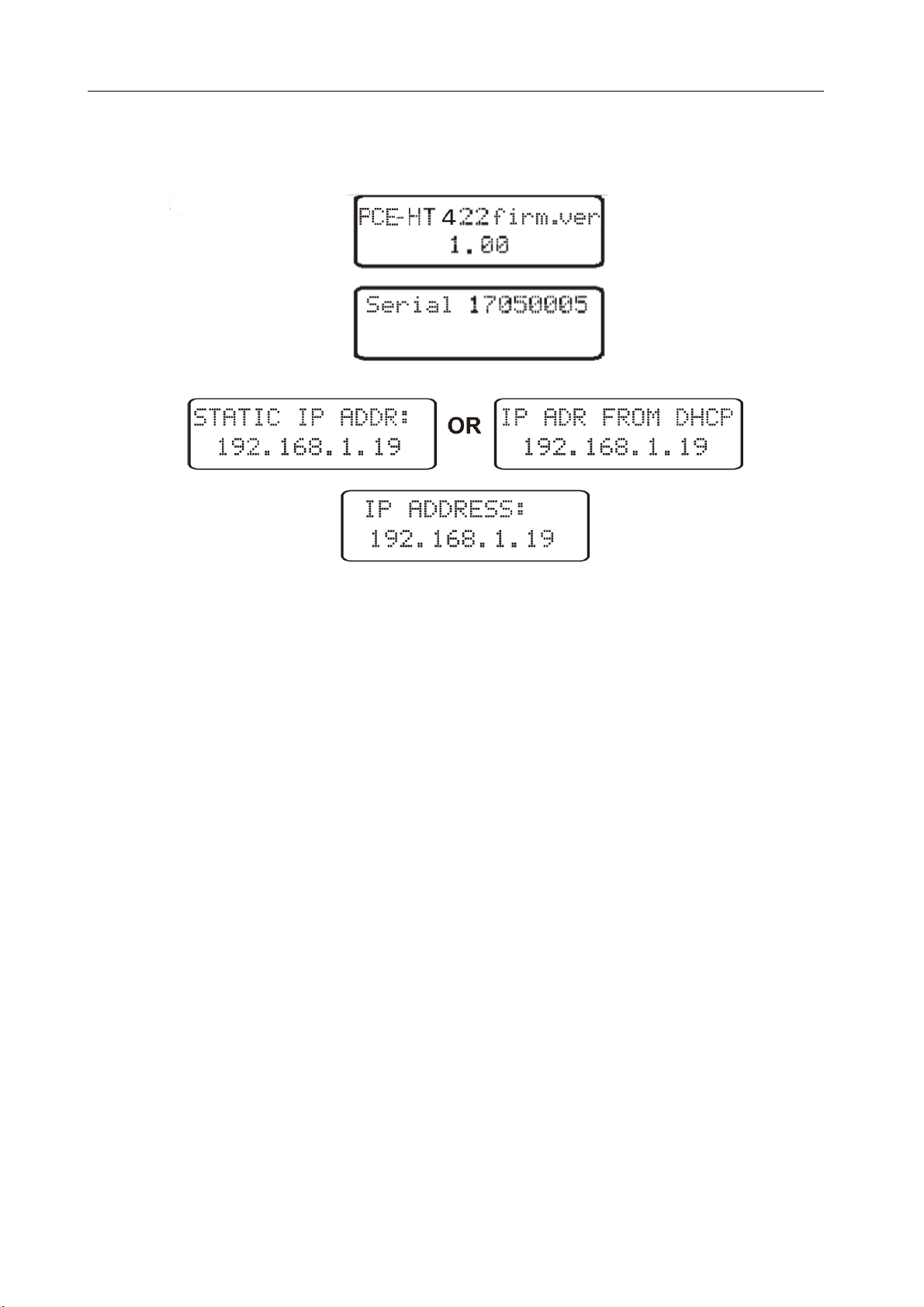
5.1. Messages after Switching the Supply on
After power is turned on the display shows the device and the manufacturer’s name
and software version. After about 4s the serial number of the device is displayed and after
subsequent 4s the I address in the network, if the device has been connected to Ethernet
network - the address can be static or obtained from DHC server.
PCE-HT 422 User’s Manua l
7
Fig. 4. Startup messages of PCE-HT 422 monitor
5.2. Functions of the button
The device contains one physical button for restoring the factory settings or
displaying the current I address of the monitor. This button is located on the connector
panel – fig. 3.
-restoring factory parameters - after pressing and holding the button for 10 seconds;
Note: each successive restoring of factory parameters enables or disables the service of
obtaining network address from a DHC server, i.e. if the DHC service is enabled and
restoring the factory parameters will be forced , the DHC service will be disabled (you will
be informed about the change by a message on the display) and default static I address
will be assigned to the device: 192.168.1.19 (subnet mask: 255.255.255.0), another
request for restoring the factory parameters will enable the DHC server service -
the network parameters will be obtained dynamically from the server;
-displaying the current IP address of the monitor – occurs after a short press
of the button – about 1 sec.

PCE-HT 422 User’s Manua l
8
5.3. Connection of the device – configuration
Configuration of the device is possible through free e-CON software, available on the
manufacturer's website (https://www.pce-instruments.com/english/download-win_4.htm).
Access to most configuration parameters is also available from the device's website via
the embedded HTT server.
5.3.1. onnection of the monitor to the network equipped with a DH P server
The easiest way to connect the PCE-HT 422 monitor to the Ethernet network is to
use an existing DHC server in the network, which assigns the communication
parameters to the devices connected, i.e. I address, subnet mask, gateway, DNS
address. In order to use the automatic configuration with DHC server, make sure the
monitor is running with DHC client service enabled - to do this, switch on the power of
the monitor and observe the initial messages:
a) message about the monitor operation with DHC
client enabled – the displayed I address is the current
address of the monitor acquired from DHC server;
b) message about the work of the monitor with disabled
DHC client service - the displayed I address is the
current address of the monitor set manually or the default
address (after restoring the default parameters); in order
to obtain the address from the DHC server, restore the monitor to the factory parameters,
point 5.2, and restart the device - then a) message should be displayed with the I
address obtained from the DHC server.
In order to further configure the device a computer (tablet, phone) must be
connected to the same Ethernet network (also with DHC client enabled - automatic
acquisition of I address), open a web browser and in the browser address field type the
I address displayed by PCE-HT 422. This will display the login screen to log the web server
that will allow further configuration - sign up to the administrator account, p. 5.6.3.2.
After gaining access to the full configuration we recommend that you disable the
DHC client, leaving the acquired network parameters unchanged – I address, subnet
mask, gateway, DNS address will be stored as static parameters.

PCE-HT 422 User’s Manua l
9
5.3.2. onnecting the monitor to the network without using DH P server
In order to use static configuration of network parameters, make sure the monitor is
running with the DHC client service disabled - to do this switch on the power of the
monitor and observe the initial messages:
a) message about the monitor operation with DHC client
service enabled – the displayed I address is the current
address of the monitor acquired from DHC server;
to set the a static I address factory parameters should be
restored, p. 5.2, and the device should be restarted – then a message should be displayed
b) with the static default I address.
b) a message about the monitor operation with disabled
DHC client service - the displayed I address is the current
address of the monitor set manually or the default I
address (after restoring the default parameters), if the
displayed address is different from 192.168.1.19 the factory
defaults should be restored twice, p. 5.2;
In order to further configure the device a computer (tablet, phone) must be
connected to the same Ethernet network (or directly to the monitor) and the automatic
acquisition of network parameters must be disabled. Then, the static parameters
corresponding to the default network parameters of PCE-HT 422 must be manually
entered into the computer (tablet, phone p. 5.6.2 (the same subnet mask and any I
address from the pool 192.168.1.X except for the address 192.168.1.19
assigned by default to PCE-HT 422). After the connection, open your web browser and
type in the address field of the browser the default I address 192.168.1.19. This will
display the login screen to log the web server that will allow further configuration - sign up
to the administrator account, p. 5.6.3.2. After logging in to the monitor web server it is
possible to change the network parameters according to our needs - especially the I
address must be changed to make sure that the monitor does not have the default I
address, otherwise the configuration of other monitors working in the same Ethernet
network will be difficult.
5.4. Functions of the onitor
Monitor PCE-HT 422 performs the following functions:
•measurement of the ambient temperature and relative humidity,
•measurement of luminous,
•measurement of the total amount of volatile organic compounds,
•measurement of CO2 concentration,
•calculation of selected physical quantities: absolute humidity, dew point
temperature, wet bulb temperature, saturated vapor pressure, enthalpy
•memory of minimum and maximum values measured and calculated:

PCE-HT 422 User’s Manua l
10
◦temperature,
◦relative humidity,
◦absolute humidity,
◦dew point.
5.5. Description of PCE-HT 422 onitor reading field
Fig. 5 escription of the PCE-HT 422 monitor reading field
The PCE-HT 422 monitor is equipped with a backlit LCD display consisting of two
lines of 16 characters each. The top line of the display is used for the presentation of
measured values - temperature and relative humidity and to display status pictographs
of the file system internal memory. The bottom line of the display shows the internal
memory usage, status of alarms, time and date. The display (top line) cyclically
changes the displayed parameters. The change interval and displayed parameters are
configurable items.
Table 1, 2 shows the symbols displayed on the LCD, and their meanings.
Table 1
Symbol Display mode Meaning
constant file system internal memory installed and ready
for operation
flashing error of file system internal memory
flashing file system internal memory full

PCE-HT 422 User’s Manua l
11
flashing file system internal memory installed and ready
for operation, active FT connection
constant Alarm activity indicator - alarms 1, 2 active
constant Alarm activity indicator - alarm 1 active
constant Alarm activity indicator - alarm 2 active
constant Alarm activity indicator - alarms inactive
Table 2
Symbol
ercentage of internal
memory usage
87.5…100%
75…87.5%
62.5…75%
50…62.5%
37.5…50%
25…37.5%
12.5…25%
0…12.5%
Measuring ranges exceedings are indicated by displaying special characters on the top
line of the LCD:
●- lower exceeding of the range of the displayed value
●- upper exceeding of the range of the displayed value
5.6. Ethernet 10/100-BASE-T
PCE-HT 422 monitors are equipped with Ethernet interface for the connection
(using RJ45 slot) to a local or global network (LAN or WAN) and the use of network
services implemented in the monitors: Web server, FT server, Modbus Slave TC /I ,
SMT client. In order to use the network services Ethernet parameters of the
monitor must be configured. Standard Ethernet parameters of the monitor are shown in
table 4. The basic parameter is the I address of the monitor - by default
192.168.1.19, which must be unique within the network to which we connect the
device. The I address can be assigned to the monitor automatically by DHC
server present on the network provided that the option to acquire I address from
DHC servers is enabled in the monitor.
PCE-HT 422 User’s Manua l
12
DHC service is disabled by default, then the monitor initializes with the default I address
allowing the user to change the I address through the website.
Caution: The monitor allows for up to 10 connections simultaneously!! The applications
implemented in the monitor use from 1 to 2 connections:
●Modbus TC /I - 1 connection
●Web server - minimum 1 connection
●FT server - 2 connections
●SMT client - 1 connection
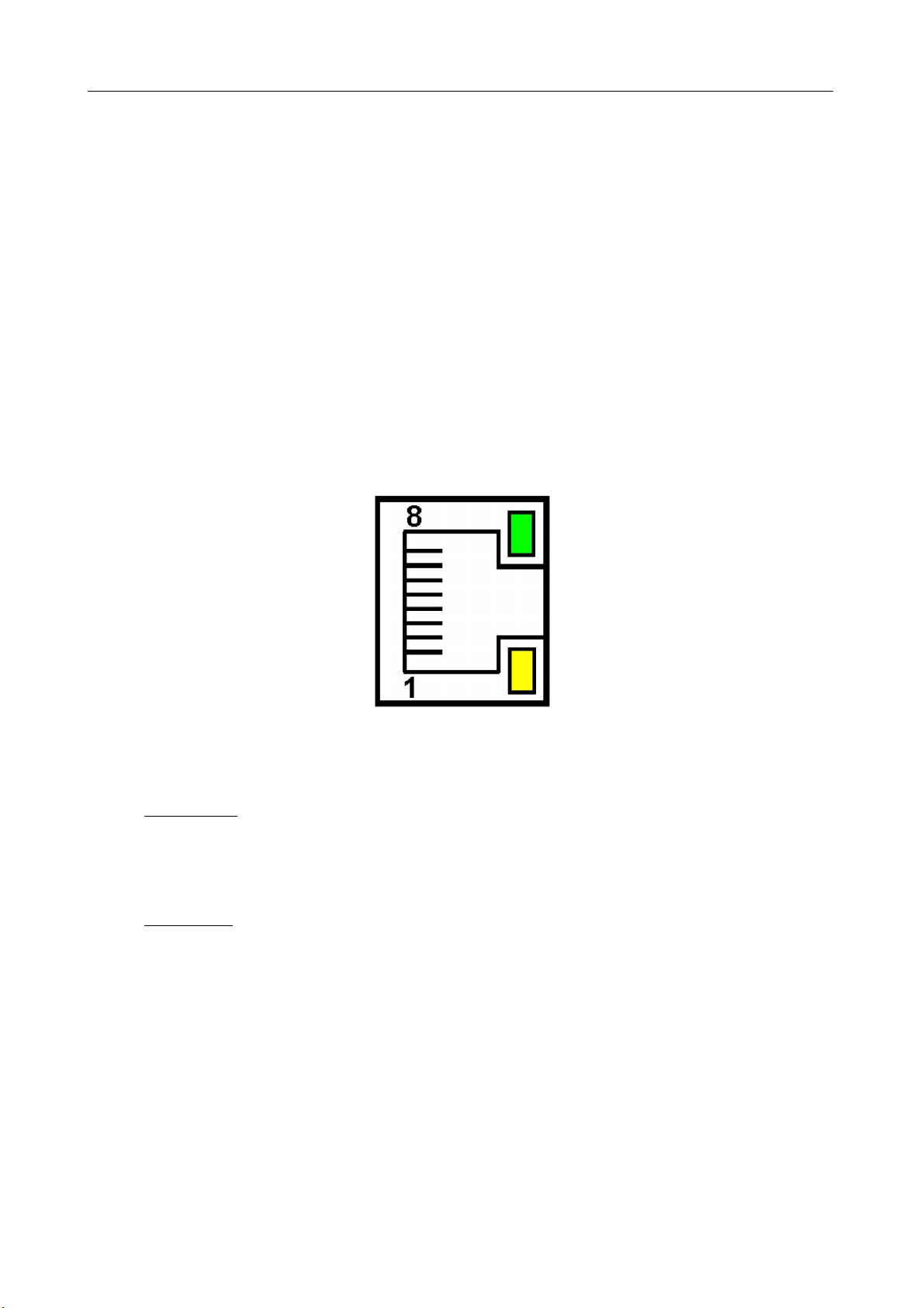
5.6.1. Connection of 10/100 BASE-T interface
To access the Ethernet services, it is required to connect the monitor to the network
via the RJ45 slot located at the top of the monitor, operating in accordance with TC /I .
Fig. 6 View and numbering of RJ45 slot pins
Description of the monitor RJ45 slot diodes function:
●yellow LED - illuminates when PCE-HT 422 is properly connected to the Ethernet
network
100 Base-T, does not light up when PCE-HT 422 is not connected to the network
or is connected to 10-Base-T network.
●green LED - Tx/Rx flickers when the monitor sends and receives data, illuminates
constantly when data is transmitted
In order to connect PCE-HT 422 to the network the user should use twisted pair cable.
●U/FT – twisted pair cable with each pair foiled,
●F/FT – twisted pair cable with each pair foiled, additionally cable with foil shield,
●S/FT (formerly SFT ) – twisted pair cable with each pair foiled, additionally cable
with wire mesh shield,

PCE-HT 422 User’s Manua l
13
●SF/FT (formerly S-ST ) – twisted pair cable with each pair foiled, additionally with
foil and wire mesh shield,
Categories of twisted pair cable according to the European standard EN 50173
minimum: Class D (category 5) - for high-speed local area networks, includes applications
using the frequency band up to 100 MHz. The description of the connection is shown in
table 3. For Ethernet interface the User should use twisted pair cable of ST type
(shielded) category 5 with RJ-45 connector with conductors colors (in accordance with the
colors described in table 3) acc. to the following standard:
●EIA/TIA 568A for both connectors at the so-called simple connection of PCE-HT
422 to the network hub or switch,
●EIA/TIA 568A for the first connector and EIA/TIA 568B for the second connector at
the so-called patch cord connection (crossover) used, among others, when
connecting PCE-HT 422 to a computer.
Table 3
Conductor
no.
Signal Conductor color acc. to standard
EIA/TIA 568A EIA/TIA 568B
1 TX+ white-green white-orange
2 TX- green orange
3 RX+ white-orange white-green
4 E WR+ blue blue
5 E WR+ white-blue white-blue
6 RX- orange green
7 E WR- white-brown white-brown
8 E WR- brown brown
5.6.2. Ethernet interface default parameters
Table 4
No. Name Default value
1. DHC Enabled or disabled
(cycled when default parameters restoration is forced)
2. I Address 192.168.1.19
3. Subnet mask 255.255.255.0
4. Default 192.168.1.1
5. DNS 8.8.8.8

PCE-HT 422 User’s Manua l
14
5.6.2.1. hanging the parameters of Ethernet interface
Changing the parameters of the Ethernet interface is possible through the built-in
web server.
Fig. 7. View of the window to change the parameters of the Ethernet interface
5.6.3 Web Server
PCE-HT 422 monitor provides its own Web server that allows remote
monitoring of measured values and remote configuration and readout of the monitor
status. With the web page the user can:
●obtain device information (serial number, execution code, firmware version,
bootloader version, variant (standard or special),
●preview the current measured values,
●read the status of the device,
●select the language for the Web page,
●perform configuration of most parameters.
PCE-HT 422 User’s Manua l
15
Access to the Web server is achieved by entering the monitor I address in the web
browser, e.g .: http://192.168.1.19 (where 192.168.1.19 is the monitor address).
The standard port for web server is port "80". Server port may be changed by the user.
Caution: For proper web page operation a browser with JavaScript enabled and
compatible with XHTML 1.0 is required (all popular browsers, Internet Explorer, version 8
minimum).
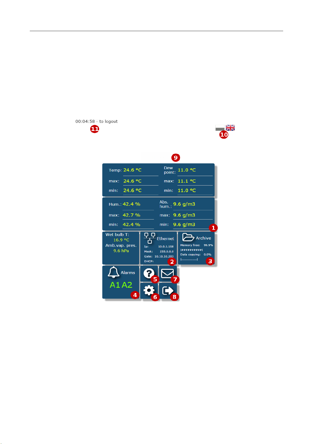
5.6.3.1 General view
Fig. 8. General view of the main website
The function of each tile of the website:
1) The view of measurements and after clicking on the tile displaying graphs with
trends.
2) Ethernet interface settings.
PCE-HT 42x

PCE-HT 422 User’s Manua l
16
3) Archive settings and information about memory usage and the process of data
dump to the file system memory.
4) Alarm settings and information about their status.
5) Information about the device, giving an individual name to the monitor.
6) Setting the time, LCD display and configuration of our displayed values - the groups
of 12 values of any registers of the monitor registers to which we can assign our
own name and display them as a separate tile on the website. Defined records can
be archived and control the alarms.
7) Email configuration.
8) Logging off, return to the login page.
9) Configurable device name
10) Changing the language
11) Time to log off during inactivity
Fig. 9. View of the window to configure the group of our own registers
PCE-HT 422 User’s Manua l
17
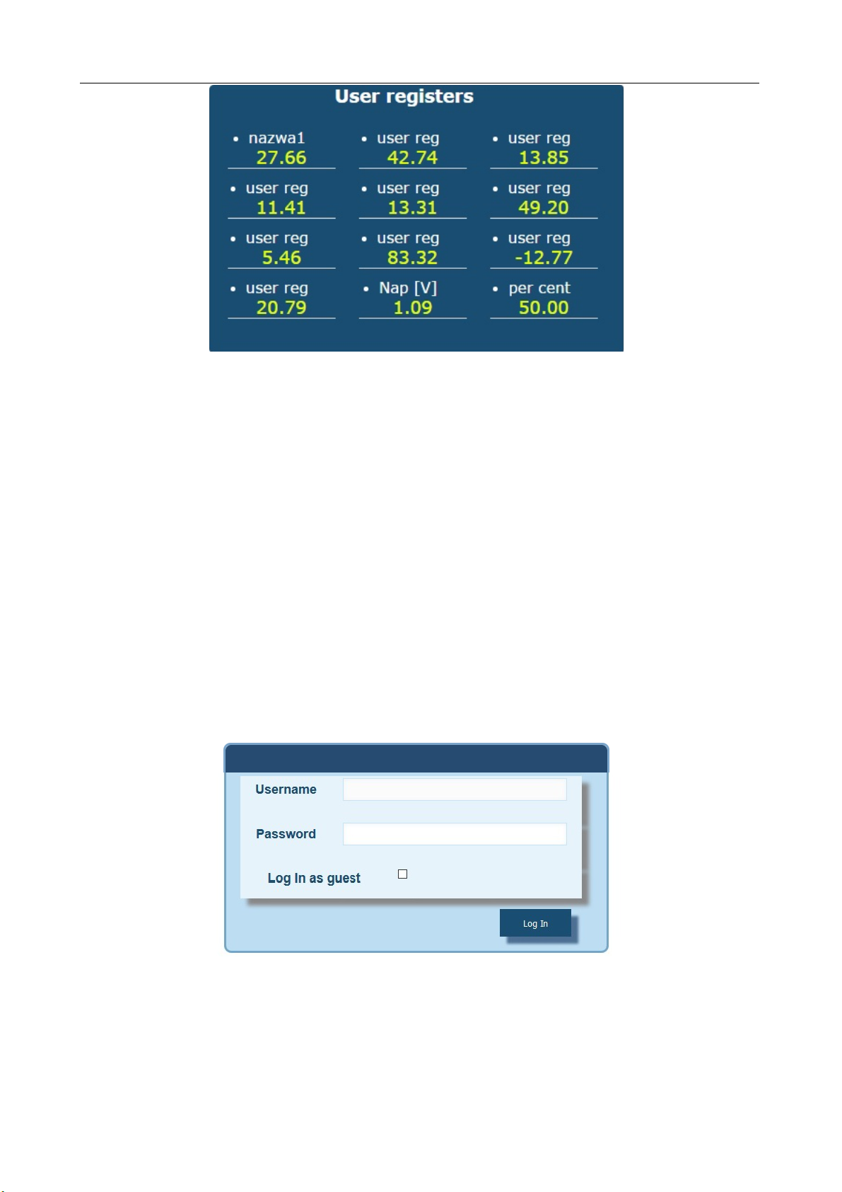
Fig. 10. View of a tile displaying a group of our 12 values
5.6.3.2. Selection of Web server user
The monitor has two user accounts for the Web server secured by individual
passwords:
●user: ”admin”, password: ”admin” - access to configuration and the preview of
parameters
●user: ”user”, password: ”pass” - access to the preview of parameters only.
●user: "guest" - access to the preview of the measured values on the home page
only, log on to the guest account does not require entering a user name or
password, it is enough to select "Login as a guest” and then click on "Login"
Fig. 11. View of the login window to the website
PCE-HT 422 User’s Manua l
18
Calling the monitor I address in the browser, for example http://192.168.1.19
will display the start window in the browser where the user must enter the name
and password. Additionally, you can log in to the "guest” account when you select “Login
as a guest” on the login page. "Guest” user account is
limited to view the measured values on the main page. Log off occurs after 5 minutes
of inactivity.
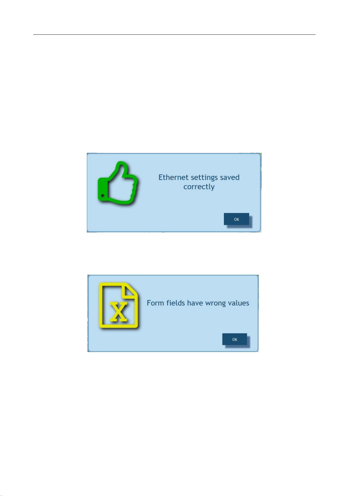
5.6.3.3. Messages to the user
The web server is equipped with a system of messages to the user. If the user tries
to save the settings into the monitor, a message is returned on the status of
such operation. For mobile applications there is a user notification system built-in
the web browser.
Fig. 12. View of the message window informing that parameters has been
correctly recorded in the device
Fig. 13. View of the message window informing about incorrect data
of the web form

PCE-HT 422 User’s Manua l
19
Fig. 14. View of the message window informing about lack of permission
to view the website content.
5.6.3.4. Access to the archive file through the web server
PCE-HT 422 allows for access to archive files through the file manager
implemented on the web server that allows the user to retrieve and delete individual
files. To start the archive file manager, click on the tile Archive, and then click the
button Browse arch. Files.
Fig. 15. View of the window of the file manager on the web server
In order to download the file, click the file icon, and to delete a file, click the trash
can symbol next to the file icon.
Table of contents
Other PCE Health and Fitness Data Logger manuals


Popular Data Logger manuals by other brands


NexSens
NexSens X2-CB user guide

NRG Systems
NRG Systems SYMPHONIEPLUS 3 instructions

MadgeTech
MadgeTech OctProcessV2 Product user guide

Calypso Instruments
Calypso Instruments ULTRASONIC Portable Solar user manual

Extech Instruments
Extech Instruments 42280A user manual

HyQuest Solutions
HyQuest Solutions iRIS 350FX user manual