Chauvin Arnoux K 1 User manual

1
■■
■■
■SONDE DE COURANT AC/DC
■■
■■
■AC/DC CURRENT PROBE
■■
■■
■AC/DC STROMSONDE
■■
■■
■SONDA AMPEROMETRICA AC/DC
■■
■■
■SONDA DE CORRIENTE AC/DC
K1
K2
OL
ON
10 mV/mA
300V CATII
OFF
AC/DC CURRENT PROBE
K2
CHAUVIN
ARNOUX
OL
ON
1 mV/mA
OFF
AC/DCCURRENTCLAMP
K1
CHAUVIN
ARNOUX
FRANCAIS
ENGLISH
DEUTSCH
ITALIANO
ESPAÑOL
Mode d'Emploi
User's manual
Bedienungsanleitung
Libretto d'Istruzioni
Manual de Instrucciones

2
CONSULTER LE MODE D’EMPLOI AVANT D’UTILISER L’APPAREIL.
Dans le présent mode d’emploi, les instructions précédées de ce symbole, si elles
ne sont pas bien respectées ou réalisées, peuvent occasionner un accident corporel
ou endommager l’appareil et les installations.
LIRE LES INSTRUCTIONS AVANT D’UTILISER L’APPAREIL !
Vous venez d’acquérir une sonde de courant K1 ou K2 et nous vous remercions de votre
confiance.
Pour obtenir le meilleur service de votre appareil :
■lisez attentivement ce mode d’emploi,
■respectez les précautions d’emploi.
PRECAUTIONS D’EMPLOI
■Ne pas utiliser les sondes K1 et K2 sur des conducteurs non isolés portés à un potentiel
supérieur à 300 V par rapport à la terre.
■S'assurer que l'appareil de mesure associé présente les mêmes caractéristiques de
protection électrique que la sonde de courant.
■Pourlesmesuresencourantcontinu,s'assurerduzérodelasortie.Leréglersinécessaire
(voir "Procédure d'emploi").
■Ne pas exposer la sonde à des chutes d'eau.
■Maintenir l'entrefer en parfait état de propreté (voir § 5.2. Entretien).
POUR COMMANDER
Sonde de courant K1 .......................................................................................P01.1200.67
Sonde de courant K2 .......................................................................................P01.1200.74
Livrées en malette de transport avec :
- 1 mode d'emploi en 5 langues,
- 1 pile 9V alcaline,
- 1 jeu d'étiquettes à coller sur l'appareil,
- 1 certificat de vérification.
Rechange :
- Pile 9V alcaline ..............................................................................................P01.1006.20
- Mallette de transport ......................................................................................P01.2980.22

11
CONSULT THE USER’S MANUAL BEFORE USING THE INSTRUMENT.
In the present User’s Manual, the instructions preceded by this symbol, if they are
not respected or followed correctly, may give rise to bodily injury or damage the
instrument and installations.
READ THE INSTRUCTIONS BEFORE USING THE INSTRUMENT !
You have just acquired a K1 or K2 current probe and we thank you for your confidence.
To get the best service from your instrument :
■read carefully this user manual
■respect the safety precautions
SAFETY PRECAUTIONS
■Do not use the K1 and K2 probes on uninsulated conductors at a potential greater than
300 V in relation to the earth.
■Ensure that the associated measurement instrument has the same electrical protection
specifications as the current probe.
■For measurements in DC current, ensure zero value at the output. Set if necessary (see
“How to use”).
■Do not expose the probe to running water.
■Keep the jaw faces perfectly clean (see Ch.5.2 Cleaning).
TO ORDER
K1 current probe ............................................................................................. P01.1200.67
K2 current probe ............................................................................................. P01.1200.74
Supplied in a carrying case with :
- 1 user manual in 5 languages,
- 9V alkaline battery,
- 1 set of labels to stick on the instrument,
- 1 test certificate.
Spares :
- 9V alkaline battery ........................................................................................ P01.1006.20
- Carrying case................................................................................................ P01.2980.22
English

12
SUMMARY
1. Presentation.................................................................................................................................... 13
2. Description...................................................................................................................................... 13
3. How to use...................................................................................................................................... 14
3.1. Switchingon ........................................................................................................................ 14
3.2. AdjustingDC zero current.................................................................................................... 14
3.3. Measurement ....................................................................................................................... 14
3.4. Overloadindication .............................................................................................................. 14
4. Specifications ................................................................................................................................. 15
4.1. Referenceconditions ........................................................................................................... 15
4.2. Operatingconditions ............................................................................................................15
4.3. Metrologicalconditions ........................................................................................................ 16
4.4. Mechanicalconditions.......................................................................................................... 18
4.5. Electrical specifications........................................................................................................ 18
4.6. Electromagneticcompatibility............................................................................................... 18
5. Maintenance ................................................................................................................................... 19
5.1. Changingthe battery............................................................................................................19
5.2. Cleaning............................................................................................................................... 19
5.3. Metrologicalcheck ............................................................................................................... 19
6. Warranty ......................................................................................................................................... 19
6.1 Repair .................................................................................................................................. 19
7. Appendices ..................................................................................................................................... 47
7.1 Error as a function of a DC primary current ......................................................................... 47
7.2 Error as a function of AC primary current............................................................................. 48
7.3 Max error as a function of the frequency.............................................................................. 49
7.4 Phase shift as a function of the frequency ........................................................................... 50
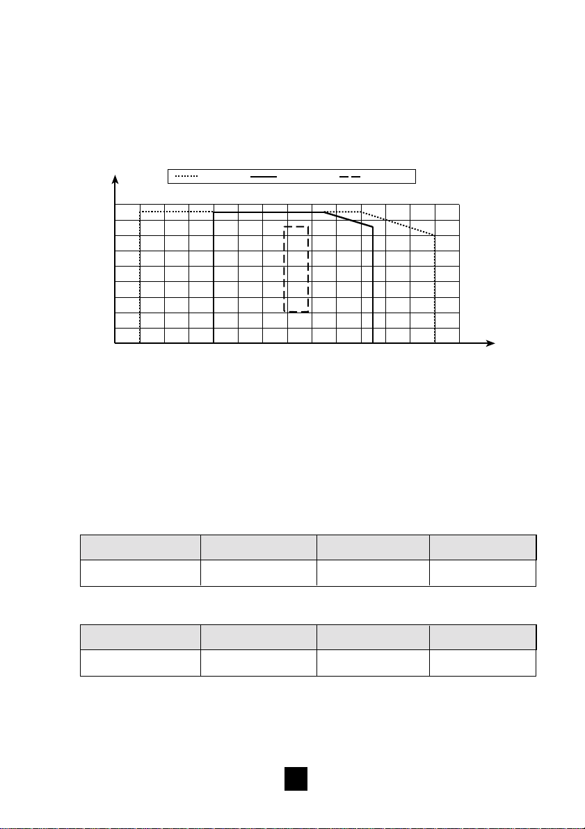
7.5 Maximumpermittedpeak current onpermanentoverload ................................................... 50
7.6 Description........................................................................................................................... 51

13
1. PRESENTATION
The K1 and K2 current probes enable the measurement of low DC or AC currents, without
opening the circuit being worked on.They connect to a multimeter or any other instrument
that has a voltage input and output impedance ³1 MW£100 pF.
These probes measure on one hand, DC currents from 1 mA to 4.5 A for the K1 probe and
from 0.1 to 450 mA for the K2 probe, and on the other hand, sinusoidal AC currents from
1 mA to 3 A for the K1 probe and from 0.1 to 300 mA for the K2 probe.
These probes output the current measured in the form of a voltage that is the image of the
primary current, in form and amplitude.
They have a single 1 mV/mA range for the K1 and 10 mV/mA range for the K2.
Both are equipped with an On/Off switch, a zero reset thumbwheel and two light indicators,
one for overload, the other for the voltage of the battery power supply.
The probe is in the form of a small clamp with a clamping capacity of 3.9 mm diameter. It
is connected to an adapter case by a multiconductor attached lead, shielded and insulated,
length 1.5 m.
In this case are the electronics of the probe and the 9V battery power supply (type 6LR61,
6LF22 or NEDA 1604). The battery life is approximately 20 hours with an alkaline battery.
The measurement output is ensured by two male safety plugs Ø4 mm, standard 19 mm
spacing, attached to the case. This case plugs directly into the associated measurement
instrument and thus leaves the user’s hands free to manipulate the clamp.
2. DESCRIPTION
The K1 and K2 consist of a sensor linked to an adapter unit by an attached cable (see
diagram on the last page of the user manual).
Sensor :
➊Passage of conductor
➋Jaws
➌Hand-held part
➍Cable attached to the sensor/case
Adapter case :
➎Adjust zero DC thumbwheel
➏On/Off switch
➐Battery “ON”indicator
➑“OL”overload indicator
➒4 mm Ømeasurement output sockets

14
3. HOW TO USE
Do not use the K1 and K2 current probes on cables or conductors at a potential
in relation to the earth , greater than 300 V.
3.1. SWITCHING ON
Put the sliding switch ➏to the appropriate position (1 mV/mA for the K1 and 10 mV/mA for
the K2).Correct operation is shown by the green “ON”light ➐which indicates good battery
condition. If this indicator does not light, or goes out, it is necessary to change the battery
(see Ch. 5.1).
3.2. ADJUST ZERO DC
■Ensure that the jaws of the clamp are correctly closed and they do not enclose any
conductor.
■Plug the output connectors ➒of the adapter case of the probe into your measurement
instrument. Switch on the probe (see Ch. 3.1).
■Select the most sensitive voltage range of your measurement instrument.
■Press the DC zero thumbwheel ➎and at the same time rotate it to obtain zero on the
display.
3.3. MEASUREMENT
After having switched on the probe :
■Connect the measurement instrument with the appropriate voltage range and adjust
zero DC (refer to Ch.3.1. and 3.2. above).
■Enclosethe conductor to measurebetweenthe jaws➊of the clamp.The valuemeasured
is displayed directly on the associated instrument as a function of the input/output ratio
of the probe.
■To obtain the value of the current in the cable, apply to the value measured, the
appropriate conversion ratio, as a function of the voltage range selected on the
measurement instrument and the sensitivity of the clamp.
3.4. OVERLOAD INDICATION
The detection of overload or overrange of the range of the probe, is signalled by the red
coloured “OL”indicator ➑. This indicator lights up for a peak current greater than 4.5 A for
the K1 and 450 mA for the K2.

15
4. SPECIFICATIONS
■Measurement range
Current DC AC Peak
K1 1 mA…4.5 A 1 mA…3 A 1 mA…4.5 A
K2 0.1…450 mA 0.1…300 mA 0.1…450 mA
■Input/output ratio K1 : 1 mV/mA
K2 : 10 mV/mA
■Rise time from 10 to 90% Vs : < 200 µs
■Rise time from 90 to 10% Vs : < 200 µs
■Output noise from DC to 3 kHz K1 : 100 µV
K2 : 1mV
■Output impedance K1 : 220 W ±15%
K2 : 220 W ±15%
■Zero adjust K1 : ±30 mA
K2 : ±15 mA
■Rollover* K1 : ±0.3% from 120 mA to 4,5 A
K2 : ±0.3% from 20 mA to 450 mA
*
Difference in measurement of 2 currents of the same value but opposite direction.
4.1. REFERENCE CONDITIONS
■Temperature : 18...28°C
■Humidity rate : 20...75% RH
■Battery voltage : 9 V ± 0.1 V
■Magnetic field : Earth’s DC field
■Impedance of the measurement instrument : •³1 MW £100 pF
■Absence of external AC magnetic field
■Absence of electric field
■Measurement for a DC current or a sinusoidal AC current 45...65 Hz
4.2. OPERATING CONDITIONS
The instrument must be used in the following conditions to satisfy the safety of the user
and the metrological performance.
■Use indoors
■Altitude : £2000 m
■Temperature : -10...+55°C
■Relative humidity
:
<85%RH ( £35°C)with linear decrease to 75%RH at 55°C
■Storage : -40...+80°C / RH £85%
■Transportation altitude : £12000 m

16
Graph of climatic conditions
Relative humidity in % of RH
0
10
20
30
40
50
60
70
80
90
-50 -40 -30 -20 -10 0 10 20 30 40 50 60 70 80 90
Storage
Use Reference
Temperature in °C
4.3. METROLOGICAL SPECIFICATIONS
Intrinsic errors
The errors specified below, correspond to measurements made in the reference conditions
(see Ch. 4.1).
■On DC current
• K1 probe
Primary current 1…10 mA 10…120 mA 120 mA…4.5 A
Error ± (2% Vs ± 0.2 mV) ± (2% Vs ± 0.1 mV) ± 1% Vs
•K2 probe
Primary current 0.1…1 mA 1…12 mA 12…450 mA
Error ± (3% Vs ± 2 mV) ± (2% Vs ± 2 mV) ± 1% Vs
Graph of max. error as a function of a DC primary current : see in appendices,
page 47.

17
■Intrinsic error on AC current 45...65 Hz
•K1 probe
Primary current 1...10 mA 10...120 mA 120 mA...3 A
Error ± (3% Vs ± 0.3 mV) ± (3% Vs ± 0.1 mV) ±1% Vs
Phase shift - -9°maxi
•K2 probe
Primary current 0.1...1 mA 1...12 mA 12...300 mA
Error ± (3% Vs ± 0.5 mV) ± (2% Vs ± 0.5 mV) ±1% Vs
Phase shift - -9°maxi
Graph of max. error as a function of an AC primary current (45...65 Hz) : see in
appendices, page 48.
Distortion parameters
■Influence of frequency on the measurement (add to the error in the field of reference) :
2% VS from 65...440 Hz
< 3 dB de 440 Hz…1.5 kHz.See graph of max error as a function of the frequency, in
appendices, page 49.
■Influence of the frequency on the phase shift : see graph of phase shift as a function
of the frequency for a current of 1 A RMS for K1 probe, and 0.1 A for K2 in appendices,
page 50.
■Battery voltage : £0.1% Vs/V
■Temperature : K1 £1% Vs/10°C
K2 £0.7% Vs/10°C
■Humidity 10...90% RH at ambient temperature : £0.2% Vs

18
4.4. MECHANICAL SPECIFICATIONS
■Drop height : 1 m on oak receptacle on concrete to IEC 1010
■Protection from shocks : 100 g to IEC 68-2-27
■Vibrations : 5...15 Hz : 1.5 mm peak
15...25 Hz : 1 mm peak
25...55 Hz : 0.25 mm peak
sweep speed 1 octave/min, duration 10 min
for each axis (3 axes) to IEC 68-2-6
■Watertightness : IP 40 to IEC 529
■Dimensions : probe (W x H x D): 111 x 15 x 25 mm
case (W x H x D) : 135 x 64 x 28 mm
cable attached probe/case : 1.5 m
■Weight of set : 250 g
4.5. ELECTRICAL SPECIFICATIONS
Permanent overload
See graph of maximum permitted peak current on permanent overload, in appendices,
page 50.
The K1 and K2 probes conform to IEC 1010-2-031 / 300 V / Installation category II.
4.6. ELECTROMAGNETIC COMPATIBILITY
■Immunity
Generic standard : EN 50082.1
Fundamental standard : IEC 1000-4-3, aptitude criteria A
with maximum degradation of :
K1 probe : - DC current : 15 mV at zero
- AC current (60 Hz) : 2 dB from 10 mA...4.5 A
K2 probe : - DC current : 100 mV at zero
- AC current (60 Hz) :2 dB from 1 mA…450 mA
■Emissivity :
Generic standard : EN 50081.1 negligible level of emissivity of the probe

19
5. MAINTENANCE
For maintenance, use only specified spare parts. The manufacturer will not
be held responsible for any accident occuring following a repair done other
than by its after sales service or approved repairers.
5.1. CHANGING THE BATTERY
When the probe is in the "On" position, if the green “ON”indicator is out, it means that the
battery is dead. To change it proceed as follows :
■Completely disconnect the probe from the circuit to measure and the measurement
instrument it is connected to.
■Undo the screws holding the base of the case in place.
■Change the 9 V battery (type 6LF22, 6LR61 or NEDA 1604).
■Put the base of the case back in place and retighten the screws.
5.2. ENTRETIEN
The probe must not enclose a cable and must be disconnected from the
measurement instrument. Never run water on the probe.
■Keep the jaw faces perfectly clean
■Cleaning the body of the probe, the case and the lead with a damp cloth moistened
with soapy water.
■Rinsing is also done with a damp cloth moistened with clear water.
5.3. METROLOGICAL CHECK
It is essential that all measuring instruments are regularly calibrated.
For checking and calibration of your instrument, please contact our accredited laboratories
(list on request) or the Chauvin Arnoux subsidiary or Agent in your country.
6.WARRANTY
Our guarantee is applicable for twelve months after the date on which the equipment
is made available (extract from our General Conditions of Sale, available on request).
■Repair under warranty or out of warranty
For any operation under warranty or out of warranty, please return the product to your
distributor.
This manual suits for next models
1
Table of contents
Other Chauvin Arnoux Tools manuals