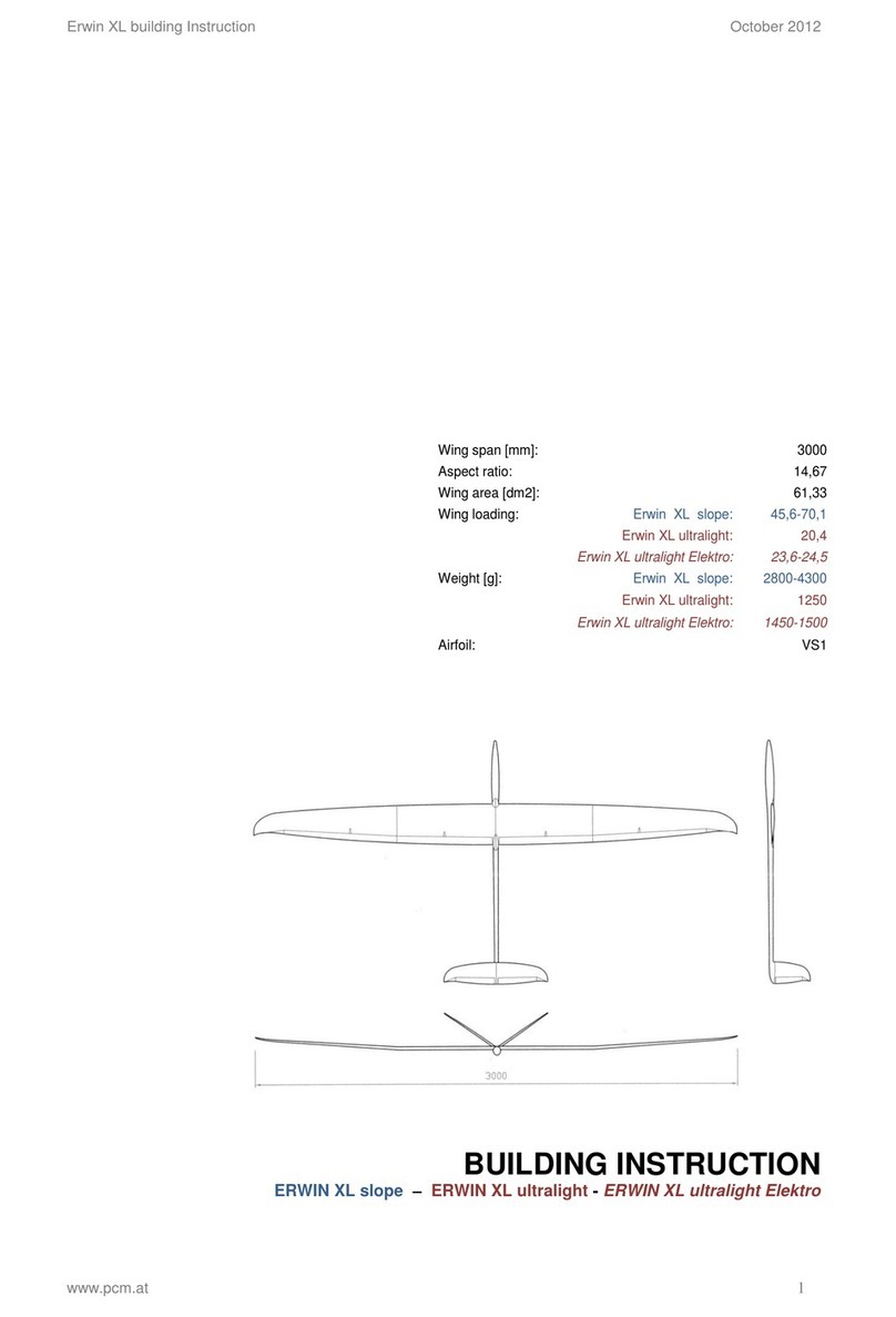
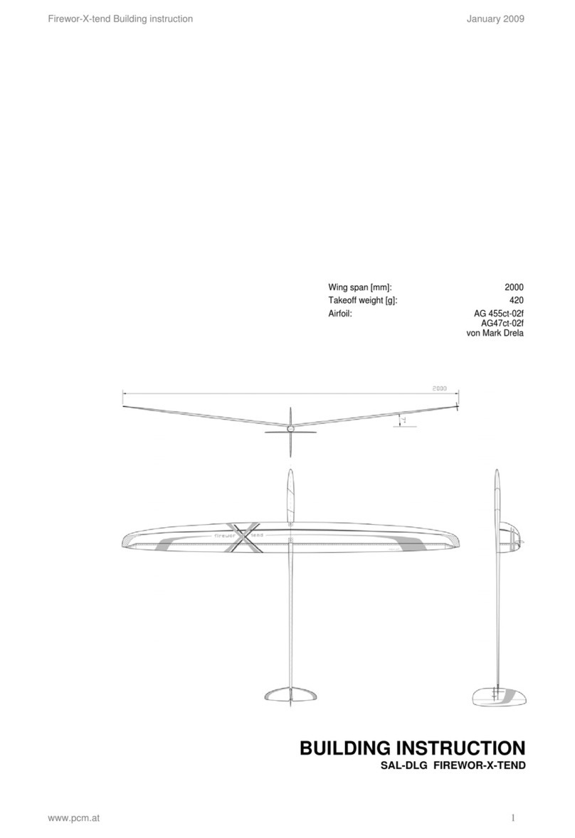
PCM FW6 Instruction Manual

FW6 Building Instruction February 2015
www.pcm.at 1
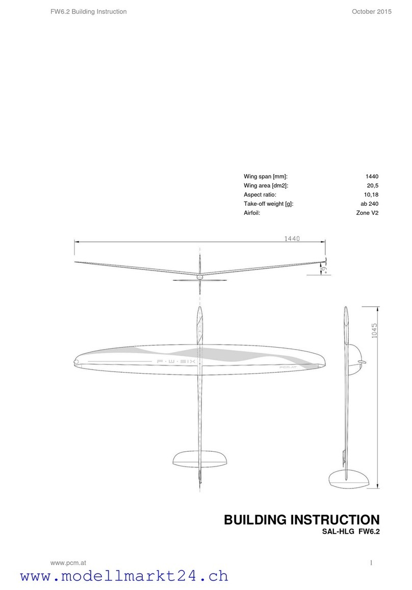
Wing span [mm]:
1440
Wing area [dm2]:
20,5
Aspect ratio:
10,18
Take-off weight [g]:
ab 240
Airfoil:
Zone V2
BUILDING INSTRUCTION
SAL-HLG FW6

FW6 Building Instruction February 2015
www.pcm.at 2
CONTENTS
DATA
1. Kit –contents
2. What else do you need?
3. Electronic equipment
ASSEMBLING THE MODEL
4. General
5. Wing
5.1 Controlling the ailerons
5.2 Installation of throwing blade
6. Fuselage
6.1 Radio board
6.2 Push rods for ailerons
6.3 Gluing the radio board
7. Installation of the CFR-stabs
7.1 Installation of torsion springs
7.2 Connection of the wires
8. Ballast
9. Battery shape and installation of receiver
10. Settings for the first flight
11. Tuning und tips
11.1 Flying weight und centering masses
11.1.1 Flight path during launch
11.2 Gigaflaps
OTHER
12. Check list before starting
13. Notes for the use
3
3
3
4
4
5
5
7
8
8
9
10
12
12
13
14
16
17
19
19
19
19
20
20
20

FW6 Building Instruction February 2015
www.pcm.at 3
DATA
1. Kit –contents
Fuselage + canopy
Wing
Rudder and elevator CFR
Radio board
CFR ballast tube
Lever for controlling rudder, 1 pc.
Lever for controlling elevator, 1 pc.
Kevlar wire for controlling rudder and elevator
Steel wire for torsion springs, 2 pc.
Brass pipes for levers of ailerons, 2 pc.
Aluminium pipes for push rods for ailerons, 2 pc.
1mm steel wire for controlling ailerons, 4 pc.
2mm carbon tubes for controlling ailerons, 2 pc.
Screws for fixing wing, 2 pc.
Nylon screws for fixing elevator, 2 pc.
Throwing blade, 1 Stk.
Lead balls for ballast
1,5mm flexible steel wire for ballast
1,5mm normal steel wire for ballast hook
Bowden cable inner tube, 3cm
D47 Servo support
Micro ball connectors
Building instruction (for download from our website)
2. What else do you need:
Epoxy-glue (for example UHU 300 endfest or Pattex Stabilit)
Super glue, both runny and thick
Carbon rovings
Electrical equipment (On/Off-switch, cables, plug...)
Electronic equipment
Shrinking tube...
3. Electronic equipment
Servo aileron:
- Graupner DS 281 (cuttings on radio board are prepared for this
servo)
Servo rudder and elevator:
- Dymond D-47 (cuttings on radio board are prepared for this servo)
Same style:
- Futaba FS31
- Modell Expert X31
Accumulators:
- GP NiMH Accu 35AAAH, Weight/cell 6g
(1,2 Volt 0,35 Ah 1/2AAA)
Receiver:
- 2,4GHz possible due to kevlar fuse cone
- Futaba R6106HFC FASST
- Multiplex RX-5 light M-link
- Mulitplex RX-6 light M-link
- Spektrum AR6115e
- Orange RX DSM2
Apart from RX-6 all receivers must be removed from their casings and
covered with heat shrink tube. See Chapter receiver installation.
FW6 Building Instruction February 2015
www.pcm.at 4
ASSEMBLING THE MODEL
4. General information on DLG-models
DLG-models are constructed strong enough to withstand the demands of starting, flying and landing
and at the same time light enough to achieve the least possible flying weight. Each part is dimensioned
to its possible minimum and produced using lightest and fewest material.
In order to continue this concept, please account the following when you assemble the model:
- Always use glue sparingly. Grind all gluing spots thoroughly, before you apply the glue.
- Electronic components should be placed as far as possible to the front, as you normally need
additional lead in the nose of the fuselage to achieve the necessary centre of gravity.
- For the same reason try to save weight especially when you finish and mount the stabilizer.
As FW6 has developed from the Fireworks-family, you will find some pictures of Fireworks 4, FW5 and
also Mini-Fireworks in the following instruction. Don’t let yourself be confused by this, the way of building
described is quite the same.

FW6 Building Instruction February 2015
www.pcm.at 5
5. FW6 wing
5.1 Controlling the ailerons
The levers of the ailerons are a brass tube and a brass M2
control horn.
For exact fixing it into the right position a plywood template is
enclosed.
The brass tubes are glued directly to the ailerons. Therefore
you have to grind the tubes and the ailerons well to guarantee a
good gluing. Use a good epoxy glue for a durable connection
(UHU 300 Endfest or Stabilith)
If the space for the brass tubes is not long enough, please extend
it as shown in the picture.

FW6 Building Instruction February 2015
www.pcm.at 6
For easy and accurate applying of the glue use the edge of a
plastic bag.
For holding the right position during the curing of the glue,
prepare distance sheets. Use them under the tube and in front
of the tube to place the tube as high as possible to the upper
edge of the aileron. Note that there is enough space near the
hinge to guarantee the free movement of the brass tube.
During curing of the glue put a strip of tape over everything to
secure the correct position of the parts.
Now you can shorten the
control horns and glue
them into the tube.

FW6 Building Instruction February 2015
www.pcm.at 7
5.2. Installation of throwing blade
The throwing blade has a molded adhesive flap. By this,
installation is greatly simplified.
Grind the gluing spots on wing and blade well and free them
from sanding dust. Then fix the throwing peg with epoxy glue.

FW6 Building Instruction February 2015
www.pcm.at 8
6. Fuselage
6.1 Radio board
First of all, push the ballast
tube into the fuselage. For
safety, you should only
stick it when all parts are
well positioned.
At the moment we
recommend the servo
Graupner DES 281.
Therefore the radio board
which is enclosed in the kit
has cuttings prepared for
this servo.
In order to utilize the
available space optimally,
we tilt the radio board
slightly. (If you look in
flight direction, the upper
edge is shifted to the right,
the lower edge to the left.)
In addition, we bend the
servo levers easily. By
this, the maximum
deflections can be
achieved.
For the rudder and
elevator we still
recommend D47 from
Dymond.
The assembly plates of the
D47 are situated a bit
deeper than the ones of
the Graupner servos.
Therefore we supply a U-
formed part to put below
the assembly plates and
lift the D47 to the same
height.
These are the tried and
tested lengths for the
levers of the servos:
Lever for aileron: 13mm
Lever for elevator: 10mm
Lever for rudder: 9mm

FW6 Building Instruction February 2015
www.pcm.at 9
6.2 Push rods for ailerons
In contrast to previous
models, we have
increased the diameter of
the pushrod and avoided
bends. By this, the
maximum force can be
transmitted without bending
of the push rods.
For this we need a special
small ball connector and
a handmade direct linkage
made of aluminum tubes.
Glue the brass part of the ball connector into the aluminium
tube. We recommend to use epoxy glue, as superglue might be
too brittle for this small joint may be too brittle.
At the other end we chose the standard version with 1mm steel
hook and securing wire. At the other servo-connection you can
just make an S-hook.
Push the steel hooks into the carbon tubes and the carbon
tubes into the aluminium tubes. Grind all gluing spots and use
epoxy glue for this bonding.
In order to achieve the correct length of the push rods, let this last
bonding harden in the assembled position. The servos and
ailerons must of course be put in zero position.
A 0.3mm steel wire will serve as protection against dismantling.
The parts are held together with a shrinking tube. Fix it the wire
with a drop of super glue.

FW6 Building Instruction February 2015
www.pcm.at 10
6.3 Gluing the radio board
Before you fix the radio
board in the fuselage, grind
all gluing spots thoroughly.
In order to gain full
strength, it is absolutely
necessary to fix the radio
board in the fuselage!
The fuselage breaks when
the servoboard is not
glued well. because of that
you have to strengthen
the gluing also with a
carbon roving.
Before you glue the radio
board, you should first find
out the optimal position.
To do so, place the radio
board inside the fuselage
without gluing and mount all
servos. The front aileron
servo should be situated
130 mm from the fuselage
tip.
You can fix the radio board
with a drop of super glue
to make the position check
easier.
Make sure that all levers
are freely movable (also
with canopy mounted), and
that the deflections of the
levers are big enough.
If necessary, the edges of the servo arms can be ground down
a bit.
Only now you can you fix the ballast tube with thin super glue.
Glue the servo board carefully with epoxy-glue (for example
UHU 300 endfest or Stabilit, no fast hardening epoxy resin).

FW6 Building Instruction February 2015
www.pcm.at 11
You can fill the glue into a small plastic bag and cut a whole
on one corner. By this, it will be easier to apply the glue
exactly.
Add carbon rovings left and right of the gluing spots for
additional strength. Best way to apply is together with
gluing of the board.
If you have a hard landing, always check if the radio board is
still fully glued before you make the next start!
Here you see how the carbon roving is placed.
The carbon roving has to be at the left and right and the upper
and lower side of the servoboard.

FW6 Building Instruction February 2015
www.pcm.at 12
7. Installation of the CFR-stabs
We use an asymmetric vertikal stab for FW6. So, first of all,
please check, if you have the correct stab for left- or
righthander.
Vertical stab for right handers: has the hinge line on the left
(seen in flight direction), see 3rd picture
Vertical stab for left handers: has the hinge line on the right
(seen in flight direction), see 3rd picture
Rudder for right-handers (view from above)
Kevlar wire to the right!
Cut a slot in the rudder in extension of the axis of the fuselage.
It is advisable to leave the lower laminate uncut. Next, glue the
lever into the slot. The hole of the lever should be located just
above the hinge line.
7.1 Installation of torsion springs:
Bend the wire according to the drawing below. Then, tip back
the control surface of the vertical stab completely. Stick the
spring into the rudder, one end into the unmoved part, one end
into the control surface near the lever.
The length of the spring should be 20mm.

FW6 Building Instruction February 2015
www.pcm.at 13
Then harden the spots with super glue.
Push the vertical stab (first for a test) into the oval end of the
boom until ist stops. Then check, if the stabilizer is aligned
correctly to the wing.
It has proven to put the entire model in a supine position on a
flat surface and then to set up the stab with an angle meter.
If you want to work quickly and build light, you can stick the stab
with thin super glue. But since the super glue is brittle, you will
certainly achieve a better bonding with epoxy glues. (UHU
300 endfest, Pattex Stabilit or similar .)
7.2 Connection of the wires
Drill a hole in the boom to lead the wire inside the fuselage to
the servo.
We stick a bowden cable into the hole, so that the rope does
not rub against the carbon edge and to reduce the weakening of
the fuselage due to the hole. This is the white pipe, which you
can see in the picture.
The small carbon lever is for the rudder and the long one for
the elevator.
Now you can hook in the kevlar wire into the lever.
Make a loop, twist the end and fix it with a drop of super
glue.
Note: Don’t use a shrinking tube, as the kevlar wire could be
damaged by the high temperature during shrinking.
Complete the elevator in the same way.

FW6 Building Instruction February 2015
www.pcm.at 14
If you want to make the most beautiful solution, you can lead
the wire out of the pylon and place the lever right behind. But
you have to shorten the lever a little for that.
8. Ballast:
As ballast we use lead balls from the fishing shop. You can
easily assemble and vary this kind of ballast.
The balls are strung on a steel wire of 1,0mm diameter. Bend
the end of the wire to a small hook. With this hook the ballast
pack can be locked on the radio board.
To locate the exact position of the ballast inside the fuselage,
lay the model on a device for measuring the centre of gravity
(see picture). Move the ballast until you get the desired centre
of gravity.
When bending the wire you should make sure that you don’t
create 180 ° curves, as the wire may break then.
Put a drop of thin super glue onto the first and the last lead
ball to fix their position. As you must curve the ball chain for
threading it into the ballast tube, bend the wire in the desired
curvature when you glue the balls.
Insert the ballast through the left opening of the fuselage into
the ballast tube.
.

FW6 Building Instruction February 2015
www.pcm.at 15
The hook of the ballast package is locked in the servo board.

FW6 Building Instruction February 2015
www.pcm.at 16
9. Battery shape and installation of receiver
Depending on the size of battery and receiver different shapes
of battery packs are possible.
In any case we recommend to assemble the battery with tape
and make a test for fitting with the receiver inside the fuselage
before you solder the battery pack.
On the right side you see two possible battery shapes
If you absolutely want to install a great 8 channel 2.4GHz
receiver, it is also possible to remove the power strip and solder
the servos directly to the board. This is quite normal with our
indoor-colleagues.
To the right a few receivers that fit well in the fuselage
(without housing):
From left to right:
- Multiplex RX-5 light M-link
- Multiplex RX-6 light M-link
- Spektrum AR 6115e
- Orange RX DSM2
Here once again these receivers, partly without housing:
- Multiplex RX-5 light M-link (without housing, housing right next
to it)
- Multiplex RX-6 light M-link
- Spektrum AR 6115e (without housing)
- Orange RX DSM2 (without housing, housing right next to it)
-Futaba R 6106HFC FASST (with and without housing)

FW6 Building Instruction February 2015
www.pcm.at 17
10. Settings for the first flight
Centre of gravity: 68-70mm (measure from the leading edge of the wing to the back)
Expo at app. 50%
Ailerons (measure near fuselage)
Flaps negative (start, speed, fast thermal search) (measure near fuselage)
Flaps positive (fast thermal search, gentle circling) (measure near fuselage)
Flaps positive (thermalling) (measure near fuselage)
Landing position (measure near fuselage)

FW6 Building Instruction February 2015
www.pcm.at 18
Snap Flap (measure near fuselage)
Snap Flap negative (for better leveling out of the flight path at the highest point of the launch)
(measure near fuselage)
Rudder (measure at deepest point)
Set the elevator on 0 at your first flight.
Don’t make a SAL-start at your first flight. Hold the glider on the fuselage and throw it gently.

FW6 Building Instruction February 2015
www.pcm.at 19
11. Tuning and tips
11.1 Flying weight and centering the masses
Our long experience has shown that the take-off weight and
centering of the masses are the most important factors to
optimize the starting height.
The model should be light.
The mass of the model should be well centered.
A lower mass can be accelerated to a higher top speed during
the discus rotation. The higher top speed, in turn, has a
significantly higher impact on the resulting kinetic energy than
the mass of the airplane. To be precise a square. Ekin = m * v²
Due to the good mass centering the oscillation of the model
after release is reduced. This means, the better the centering of
masses is, the less it slows down.
The centering of masses is also improved by loading more
ballast. This increases the flying weight, but everyone should try
out, what is his personal optimum. Every pilot has his own
optimal weight of glider, which he can accelerate best.
In addition, the amount of ballast depends of course on the
strength of wind and thermals. The Zone V2 can tolerate ballast
very good, and you should not fly with too little weight at higher
wind speeds.
As you can see, there is still plenty of room to optimize.
To put it into numbers, Mark Drela has developed a method to
measure the yaw of gyration. This defines how good or bad a
glider has centred its masses:
Hang your model upside down on two 1,5m long threads, which
you fix 30mm from the centre of gravity. Now move the glider
for 45° and the let it swing. Take the time of 5 swings. Repeat
this process several times to get an average value.
The faster the model swings, the faster it will stabilize after the
launch and the higher it will start.
11.1.1 Flightpath during start
You could reach more starting height when you adjust the
flightpath to the wind strength. When the wind is weak you
should start very steep into the sky. And when the wind is
strong the flightpath should be much more flat.
11.2 Gigaflaps (triangular ends)
In order to move the triangular ends of the ailerons , use a piece
of adhesive tape to connect the triangle to the aileron.
Always TEST THE RECEPTION on ground before you fly!

FW6 Building Instruction February 2015
www.pcm.at 20
OTHER
12. Check list before starting:
1. Check centre of gravity
2. Check control surfaces:
Do control surfaces move in the correct direction?
Check the greatest swings
3. Check reception
4. Check control surfaces before each flight.
Do all control surfaces still move correctly?
Is there enough power in the accumulator?
Are the brakes retracted?
You can save the retraction of the brakes in your start
setting. By this, you can never start with extended
brakes.
5. Gentle launch from the fuselage. No DLG-launch at your
first flight. If there are some wrong settings, everything
will go too fast at the disc-launch to correct these
failures by steering.
13. Notes for the use
To avoid heating of the carbon surface, models with carbon
wings should not lie in the sun.
During flight heating by the sun is no problem, as the model is
cooled by the wind. On ground the glider should be kept
inside protective bags or in the shade.
After every ungentle landing, you must check your model for
possible damage, such as:
- Is the radio board still glued thoroughly?
- Did the leading edge of the wing burst open?
- Did rudder or elevator get damaged?
Even a small damage could lead to write-off at your next
launch!
Table of contents
Other PCM Toy manuals

PCM
PCM ERWIN XL slope User manual

PCM
PCM ERWIN XL slope User manual

PCM
PCM FW5 FloW Instruction Manual

PCM
PCM SAL-DLG FIREWOR-X-TEND Instruction Manual

PCM
PCM Erwin XL User manual

PCM
PCM DV8R Technical specifications

PCM
PCM Erwin XL Ultralight Electro User manual

PCM
PCM FW6.2 User manual

PCM
PCM ELVIRA User manual

PCM
PCM GLIDER MINI-RACE User manual
Popular Toy manuals by other brands

marklin
marklin 24611 instruction manual

Bengtson Company
Bengtson Company Mister Mulligan instructions

Eduard
Eduard He 111 H-6 seatbelts STEEL manual

Eduard
Eduard SM-79-II Sparviero Exterior Assembly instructions

Mega Bloks
Mega Bloks Barbie Build'n Play Bakery Shop manual

GREAT PLANES
GREAT PLANES helicat instruction manual