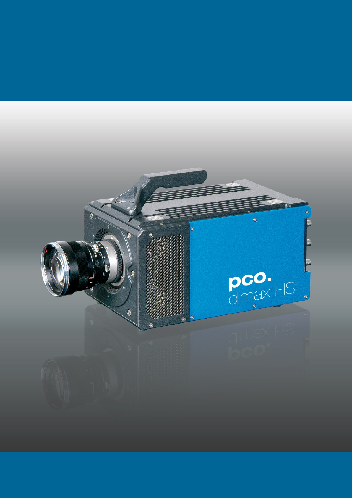
Pco dimax S User manual

pco.
dimax family
S / HD / HS
pco.
user manual

PCO asks you to carefully read this manual before using the
pco.dimax camera system and follow the instructions.
In case of any questions or comments, contact us at PCO.
telephone +49 (0) 9441 2005 50
fax +49 (0) 9441 2005 20
email info@pco.de
postal address PCO AG
Donaupark 11
93309 Kelheim, Germany
The cover photo shows an exemplary PCO camera system.
The lens is sold separately.
Copyright © 2017 PCO AG (called PCO in the following text), Kelheim,
Germany. All rights reserved. PCO assumes no responsibility for errors or
omissions in these materials. These materials are provided as is without
warranty of any kind, either expressed or implied, including but not limited to,
the implied warranties of merchantability, fitness for a particular purpose, or
non-infringement. PCO further does not warrant the accuracy or
completeness of the information, text, graphics, links or other items
contained within these materials. PCO shall not be liable for any special,
indirect, incidental, or consequential damages, including without limitation,
lost revenues or lost profits, which may result from the use of these materials.
The information is subject to change without notice and does not represent a
commitment on the part of PCO in the future. PCO hereby authorizes you to
copy documents for non – commercial use within your organization only. In
consideration of this authorization, you agree that any copy of these
documents, which you make, shall retain all copyright and other proprietary
notices contained herein. Each individual document published by PCO may
contain other proprietary notices and copyright information relating to that
individual document. Nothing contained herein shall be construed as
conferring by implication or otherwise any license or right under any patent or
trademark of PCO or any third party. Except as expressly provided, above
nothing contained herein shall be construed as conferring any license or right
under any PCO copyright. Note that any product, process, or technology in
this document may be the subject of other intellectual property rights
reserved by PCO, and may not be licensed hereunder.
Released September 2017 © PCO AG
pco.dimax User Manual V2.14 © PCO AG, Germany

3
TABLE OF CONTENTS
1. INTRODUCTION 5
1.1 MAIN FEATURES 5
1.2 INTENDED USE 6
2. SAFETY INSTRUCTIONS 7
3. SYSTEM COMPONENTS 8
4. INSTALLATION 9
4.1 DRIVER 9
4.2 CAMWARE 10
5. QUICK START 11
5.1 PREPARATION 11
5.2 START 11
5.3 FIRST IMAGE 12
6. CAMWARE 4 SOFTWARE13
6.1 CHAPTER OVERVIEW 13
6.2 CAMERA OVERVIEW / LIST 14
6.3 CAMERA PROPERTIES 16
6.3.1 TIMING 17
6.3.2 IMAGE SIZE 24
6.3.3 SENSOR CONTROL 25
6.3.4 MEMORY 26
6.3.5 RECORDING CONTROL 26
6.3.6 STATUS 30
6.3.7 HARDWARE I/O CONTROL 31
6.3.8 CONVERT CONTROL 33
6.4 IMAGE OVERLAY 35
6.5 RECORDER TOOLS 36
6.6 VIEW WINDOW 38
6.7 RECORDER (IMAGES) 39
6.8 SETTINGS OVERVIEW 41
6.8.1 AUTO SAVE 42
6.9 CAMWARE MENU TABS & FEATURES 44
6.9.1 DEMO MODE 44
6.9.2 FILE MENU 45
6.9.3 CAMERA MENU 47
6.9.4 ACQUISITION MENU 48
6.9.5 VIEW MENU 48
6.9.6 WINDOW MENU 50
6.9.7 HELP MENU 50
6.9.8 VIEW WINDOW MENU 51
6.9.9 ADDITIONAL FEATURES 53

4
APPENDIX 54
A1 TECHNICAL DATA 55
A1.1 SPECIFICATIONS 55
A1.2 REAR PANEL 56
A1.2.1 RJ45 TO LEMO ADAPTER 57
A1.2.2 PIN ASSIGNMENT OF LEMO CONNECTOR 58
A1.3 MECHANICAL DIMENSIONS 59
A1.4 INPUT WINDOW FILTER 59
A1.5 F-MOUNT ADAPTER 60
A1.5.1 PCO F-MOUNT ADAPTER 60
A1.5.2 CHANGE F-MOUNT ADAPTER 61
A2 INTERFACES 62
A2.1 CABLING 62
A2.2 USB 2.0 / 3.0 63
A2.3 GIGABIT ETHERNET 64
A2.3.1 QUICK INSTALLATION GUIDE 64
A2.3.2 NETWORK INTERFACE CARD 65
A2.3.2.1 IP ADDRESS CONFIGURATION 66
A2.3.2.2 JUMBO PACKETS / BUFFER SETTINGS 67
A2.3.2.3 RECOMMENDED HARDWARE 68
A2.3.2.4 NETWORK ENVIRONMENT/PATCH CABLE 68
A2.3.2.5 CABLE LENGTH 68
A2.3.3 SINGLE/MULTIPLE CAMERA OPERATION 69
A2.3.3.1 SINGLE CAMERA 69
A2.3.3.2 MULTIPLE CAMERAS 70
A2.3.3.3 SWITCH 70
A2.3.3.4 SEVERAL NICS 71
A2.3.4 DRIVER INSTALLATION 72
A2.3.4.1 UNINSTALL DRIVER 73
A2.3.4.2 DE/ACTIVATING FILTER DRIVER (WIN7/8) 73
A2.3.5 CALIBRATION TOOL 74
A2.3.5.1 FIRMWARE WARNING 75
A2.3.5.2 BLOCKED ACCESS 75
A2.3.5.3 NETWORK AND PACKET DELAY 76
A2.3.5.4 SET CAMERA IP ADDRESS & PACKET DELAY 77
A2.3.5.5 IMAGE DATA TRANSFER RATE 78
A2.3.5.6 CAMERA TEST 78
A2.3.5.7 TOOL TIPS 79
A2.3.6 HELP GUIDE 79
A2.3.7 PERFORMANCE 80
A2.4 CAMERA LINK 81
A2.4.1 FRAME GRABBER INSTALLATION 81
A2.4.2 MICRO DIAGNOSTICS TOOL 82
A2.5 HD-SDI 83
A3 BATTERY OPERATION 84
A4 IMAGE FILE FORMATS86
A5 CUSTOMER SERVICE 88
A5.1 SERVICE 88
A5.2 MAINTENANCE 88
A5.3 RECYCLING 88
A5.4 LOGFILE / SUPPORT FILE 89
A5.5 TROUBLE SHOOTING 90
A6 INDEX 91
ABOUT PCO 92

5
1 INTRODUCTION
1. INTRODUCTION
High-speed meets high resolution.
This high-speed 12 bit CMOS camera family incorporates
advanced CMOS and electronics technology. It is perfectly
suited for high-speed camera applications such as material
testing, off-board crash or impact tests or super slow motion
movie clips. The camera systems feature also a variety of
trigger options to cover all off-board applications required by
the automotive industry.
1.1 MAIN FEATURES
pco.dimax
S1 / S4
pco.dimax
HD / HD+
pco.dimax
HS1/2/4 (mono)
Maximum
resolution
(pixel)
S1: 1008x1008
HD: 1920x1080
HS1: 1000x1000
HS2: 1400x1050
S4: 2016x2016
HD+: 1920x1440
HS4: 2000x2000
Maximum
speed
@full resolution
(fps)
S1: 4467
HD: 2128
HS1: 7039
S4: 1279 (mono)
HS2: 5469
S4: 1102 (color)
HD+: 1603
HS4: 2277
•12 bit dynamic range
•Color or monochrome image sensor versions available
•Correlated Double Imaging for superior image quality
•Exposure time range 1.5 μs - 40 ms
•Integrated image memory (RAM up to 36 GB)
•Double shutter operation (standard for S/HS, optional for HD)
•GigE and USB 2.0/3.0 or Camera Link data interfaces
(HD-SDI optional)
•Multiple trigger interface
•Smart battery control (optional) for 1h full operation or 6h data
backup
•IRIG-B (standard for S, HS - optional for HD/HD+) B000 through
B007; B120 through B127

6
1.2 INTENDED USE
This camera system is designed for use by technicians, engineers
and scientists. It is a scientific measuring instrument, which provides
images. The camera may only be used according to the instructions
of this manual. Provisions, limitations and operating conditions stated
in this manual must be respected. Unauthorized modifications and
alterations of the device are forbidden for safety reasons.
Areas of Application
•high-speed particle image
velocimetry (PIV)
•short time physics
•spray analysis
•hyper velocity impact studies
•automotive crash tests
•material testing
•tensile tests
•airbag inflation
•fast flow visualization
•3D high-speed
photogrammetry
•hydrodynamics
•fuel injection
•sparks in electronic
switches
•combustions imaging
•semiconductor quality
control
•fast events in nature and
industry
•super slow motion movie
clips
•ballistics

7
2 SAFETY INSTRUCTIONS
2. SAFETY INSTRUCTIONS
Read the safety instructions completely.
DAMAGED POWER CABLE OR POWER PLUG
Danger to life due to electrical shock!
Each time the camera is used, check the power cable for
damage.
ELECTRIC SHOCK WARNING DUE TO VOLTAGE PARTS INSIDE
Risk of injury due to electrical shock!
Never slide any items through slits or holes into the camera.
MOISTURE
Risk of injury due to electric shock if moisture enters the camera.
To avoid the risk of water condensation, protect the camera
against extreme changes of ambient temperature.
TRIPPING HAZARD
Risk of injury from tripping over loose cables.
Never position the cable in a way that it could become a
tripping hazard.
HUMIDITY, DUST OR RADIATION
Humidity, dust or X-rays could damage the camera.
Never operate the camera in humid or dusty environments
or in places with high levels of x-ray radiation.
SHOCK & VIBRATION
To avoid damaging the camera it must be firmly mounted and
protected against strong shocks or vibrations.
Use the camera's mounting threads to secure it.
LENS MOUNTING
Do not force the lens onto the camera.
To protect the lens connector thread from damage, use
minimal force when attaching a lens to the camera.
LIQUIDS DAMAGE CAMERA
If liquids have penetrated the device.
Switch the camera off immediately, detach it from power and
contact PCO's customer support.
DAMAGED CAMERA HOUSING
If the camera has been dropped or the camera body is damaged.
Switch the camera off immediately, detach it from power and
contact PCO's customer support.
IF CAMERA IS NOT WORKING PROPERLY
In case all actions following this manual to get the camera working
properly were unsuccessful... If, after thoroughly reviewing the
instruction manual, the device is still not operating properly.
Switch the camera off immediately, detach it from power and
contact PCO's customer support.
NOTICE
NOTICE
NOTICE
NOTICE
NOTICE
NOTICE
DANGER
WARNING
CAUTION
CAUTION

8
3. SYSTEM COMPONENTS
The camera system includes following parts
Camera
F-mount optical connection, see A1.5
Rear panel connections (see A1.2)
•Power Input (12-36 VDC)
•ON/OFF Switch
•Dust Filter (exchangeable)
•Interface (GigE – USB 2.0/3.0 – CameraLink – HD-SDI optional)
•Lemosa Connectors (Automotive / industrial applications)
•LED indicates camera status
•Serial Number Tag
•Input/Output BNC connectors (Trigger – Acquire – IRIG-B –
Status – Sync-in/out)
Mounting Thread
3x 3/8
''-
16 UNC and 4x M8 threads (bottom) and 2x 1/4"- 20 UNC (top)
Battery Pack (optional)
Lithium Iron Phosphate (LiFePO4) battery, see A3
Power Supply
24V AC external Power Supply ETF150-24
Power Cord
Standard IEC13 connector
Cable
Depending on your interface, see A2.1
Digital Camera Tools (USB flash drive content)
•Camware: software for camera control & image acquisition
•Manuals
•Driver & tools
•Software Development Kit (SDK) & demo programs in C and C++

9
4 INSTALLATION
4. INSTALLATION
You will find all necessary files on the accompanying USB flash drive.
You may also download the latest versions of our software, camera
driver and third party software drivers from our website.
Minimum system requirements:
•Clock speed > 2.4 GHz (Intel Core i7)
•RAM 4 GB
•Windows 7 or higher (no server version)
•HD-resolution display
•USB 2.0 or GigE (1000Mbps network interface card)
4.1 DRIVER
Interface:
Install the appropriate driver for the interface you want to use.
The pco.dimax camera has many different interfaces, read chapter
A2. This chapter describes configuration and installation of all
different interfaces is described
•USB 2.0 / 3.0 A2.2
•GigE A2.3
•Camera Link A2.4
•HD-SDI A2.5
NVIDIA Cuda Driver:
Update your NVIDIA driver for Camware 4 GPU Processing will not
work and therefore slow image processing.
Check if GPU Processing is activated by having
a look into the Proc config settings in the
Convert Control window (see Convert
Control chapter 6.3.8).
If GPU Processing is disabled and shown
grayed, update your NVIDIA driver or check the
website of the computer manufacturer for
graphic card driver updates. Your NVIDIA driver
version must be at least 333.11 or higher.
NOTE
Using Camware with more than one interface, connect your
cameras only with the same data interface. Only use one single
interface: CameraLink or GigE/USB. Priority of USB over GigE
when both connections are used at the same time! Commands
over GigE will be ignored
1
2
1
2

10
4.2 CAMWARE
The Camware Windows application software enables you to control
every camera parameter or setting. Images can be displayed on a
monitor and may be downloaded and stored. The USB flash drive
contains the software installation files for latest Windows operating
systems in 32 & 64 bit.
After a successful installation, you will find the program file Digital
Camera Toolbox in your program directory and a Camware 32/64
button on your desktop. Other helpful tools are also installed in the
same directory.
To uninstall the Camware program, use the Software feature under
Windows’ System Control.
Follow the installation wizard
-Install Camware as Admin to install to program folder, otherwise
it will be installed only to user folder
-Choose install directory
-Choose components: select additional drivers for Camera Link
Interface
-After the next two screens installation is complete
1
2
3
4
1
1
2
3
4

11
5 QUICK START
5. QUICK START
In order to get familiar with your new camera and software it might be
helpful, first to aim the camera at an object easy to focus and visible
at normal light conditions.
5.1 PREPARATION
•Computer is turned on
•Installation is finished (see chapter 4)
•An appropriate lens is attached (remove cap) or the camera is
attached properly to the microscope, spectrograph or other
scientific device
•Camera is connected to the power supply
•Camera is connected to the computer and switched on
•Camera is booted and ready after 40s when a beep sounds
5.2 START
Start Camware and the graphical user interface will start up:
NOTE
Always install latest Camware version to get the full functionality of
your camera (www.pco.de/support).

12
5.3 FIRST IMAGE
Follow the instructions:
•Camware must be started
•A view window is shown automatically, if not open a new one
•Start live preview
•Right-click into the view window and apply Continuous Auto
Range
•You may have to adjust exposure time , aperture and focus
•Now you should clearly see the object in the window
If you need to change
exposure time (e.g. the image
is still either too dark or too
bright), go to chapter 6.3.2.
For recording and saving
images, see chapter 6.3.8 and
chapter 6.6 for detailed
information.
NOTE
Live preview: Useful for fast and easy camera adjustment and
focusing. Does not record or store images.
2
3
4
5
6
2
3
6
4
5
1
1

13
6 CAMWARE 4 SOFTWARE
6. CAMWARE 4 SOFTWARE
PCO’s Camware is an outperforming software for camera
control, image acquisition and archiving of images in various
file formats. This chapter provides a detailed description of all
Camware functions.
Camware works with any kind of PCO camera. Visit PCO
website for the latest version of this software.
6.1 CHAPTER OVERVIEW
Chapter 6.2: Camera Overview / List: shows all connected cameras
and all set recording profiles
Chapter 6.3 describes the Camera Properties window.
6.3.1 TIMING
Exposure time / FPS based /
Trigger modes/ Synchronization
6.3.2 IMAGE SIZE
ROI
6.3.3 SENSOR CONTROL
CDI / Double image / BW noise
filter
6.3.4 MEMORY
Camera internal memory (RAM)
6.3.5 RECORDING CONTROL
Recorder mode / Acquire mode /
Timestamp / Sequence trigger
6.3.6 STATUS
Temperature
6.3.7 HARDWARE I/O CONTROL
Input / Output options
6.3.8 CONVERT CONTROL
Contrast / Saturation / Gamma
Chapter 6.4 / 6.6 / 6.7 / 6.8 describe the recording functions
6.4 IMAGE OVERLAY
Overlay for recorded images
6.5 RECORDER TOOLS
Record / Play / Settings
6.6 VIEW WINDOW
View window functions
6.7 RECORDER (IMAGES)
Preview of recorded images
6.8 SETTINGS OVERVIEW
Overview of all parameter settings /
Auto Save
Chapter 6.9 introduces to further Camware features:
6.9.1 DEMO MODE
If no camera is connected
6.9.2 FILE MENU
Open / Save / Print files / Direct
record to file / Options / AVI Codec
Dialog / Lookup table
6.9.3 CAMERA MENU
Camera control / Close / Rescan
6.9.4 ACQUISITION MENU
Live preview / Acquire sequence /
Auto camera RAM segment
switching
6.9.5 VIEW MENU
B/W or Color window / Convert
Control / Toolbars / Application
Look / Reset layout to default
6.9.6 WINDOW MENU
New / Close / Split window
6.9.7 HELP MENU
Create Support file/ Logging /
Support mail / About Camware
6.9.8 VIEW WINDOW MENU
Right-click menu: Zoom; Flip;
Mirror; Rotate…
6.9.9 ADDITIONAL FEATURES
White Balance, Contrast, ROI by
Mouse, Short-cut list

14
6.2 CAMERA OVERVIEW / LIST
If closed, open the Camera Overview
window by selecting the View tab and
Toolbars and Docking Windows →
Camera Overview.
The Camera Overview window supports management of more
than one PCO cameras and displays a list of the connected ones.
It displays a list of all connected PCO cameras. Camware is able
to scan 2 for connected cameras or close a connected camera. It
allows to define several different Settings for each camera (max.
30 sets per camera →add new set 3 ).
New view windows 4can be opened and the Live Preview 5
function started. When opended up, the Preview shows a small
preview window 6 (always monochrome) integrated in the
camera list.
Live preview facilitates the aperture and focus adjustment,
allowing a first look at your object. During live preview no images
are saved neither in the computer's nor in camera's RAM.
During Live preview Trigger and Acquire mode are set to Auto.
Camera Setting: all Presettings in the Camera Properties (see 6.3)
are saved to Camera Settings. Define different Settings with
different Preferences in Camera Properties for each of your
experiments. Settings can be switched easily at any time (not during
record) and copied to other cameras.
Link Preview Set to ‘Preview’
When Link Preview Set to Preview is ticked the Preview will
always be active with the set parameters when starting a Live
Preview 5 .
In case this function is deactivated, the Live Preview will always
show live images with the parameters of your active setting.
Setting a higher exposure time for Preview set and linking it to
the preview function is beneficial if preview light conditions are
different from those in recording situations.
1
1
3
5
2
2
3
4
5
6
6
4
5

15
6 CAMWARE 4 SOFTWARE
1
2
3
Click and drag camera setting: copy e.g. Camera Setting 1 to
Camera Setting 4, just drag & drop Setting 1 to Setting 4 and
Camware will ask if you want to copy the settings. Confirm it. It is
possible to copy each setting to every camera.
Master Sets
This function facilitates the image acqusition with multiple
cameras. Defining two or more Master Sets allows easy
switching between different predefined settings for each camera
during an experiment.. Each image acquisition or experiment can
be recorded with its own Master Set.
To display Master Sets, right-click in the Camera Overview
window and select Show Master Sets.
Master Set window
Define different Master Sets. Select individual Camera Settings
within each Master Set.
Functions:
Add Master Set or Remove active master .
Activate it by clicking on one of your sets .
1
2
3

16
1
2
3
6.3 CAMERA PROPERTIES
The Camera Properties window in Camware is the main interface for
all camera settings. The active set in Camera list is adjusted here.
The former topic Camera Control (known from Camware 3.x) and
the Convert Control (see 6.3.8) can be opened additionally.
Three view options with various functions can be selected: Basic,
Custom and Expert.
Basic mode 1 only shows camera infos, exposure time / delay time,
image size (ROI – Region of Interest) and temperature settings. In
Basic Mode the frame rate is always calculated automatically based
on the selected exposure time, i.e. while exposure time is increased,
frame rate decreases. It is recommended for Camware beginners.
Custom mode shows several more setting possibilities and
functions are hidden or shown by the Custom Properties Button.
Beside to the Basic mode many more options are selectable.
Expert mode (for advanced users) shows all possible camera
feature settings.
An explanation for each feature is displayed below the properties
dialog.
2
3
4
4
1

17
6 CAMWARE 4 SOFTWARE
Exposure
n
Read-
out
n + 1
n + 2
n
n + 1
n + 2
t
exp
t
readout
6.3.1 TIMING
General Information
The most important parameter for a high-speed camera is the
frame rate. The upper limit of the frame rate is defined by the
exposure time and the readout time.
In this context trigger means exposure trigger, i.e. the trigger
signal controls the exposure of a single image.
Exposure and readout of one image are done simultaneously,
i.e. while image nis being read out from the sensor, image n+1
is already integrated within the sensor’s pixel elements.
In case of short exposure times, the readout time is the limiting
factor, i.e. a new image can only be recorded, if the last image
is read out.
For long exposure times, the exposure time is the limiting factor:
Trigger Modes
Auto Sequence:the camera optimizes the image recording to
achieve the best possible frame rate. In the Auto Sequence mode,
the camera determines the highest possible frame rate against the
set exposure time and the time required for a frame readout. Upon a
start command the sequential recording starts and lasts until a stop
command.
Soft Trigger:single images are recorded by this Camware
command. A single image is acquired by pressing the Single Trigger
button. This button appears after pressing the Start Record button.
Other signals have no influence on this operating mode.
Ext. Synch.(BNC Exp. Trig.): in addition to the Master / Slave
camera synchronization mode (see Camera Synchronization p.19)
the pco.dimax also uses an external synchronization signal feeding a
phase-locked loop (PLL) in the camera.
NOTE
As the pco.dimax is a
high-
speed camera,
triggering single im-
ages using the Soft
Trigger button will
result in a significantly
degraded image qua-
lity (noisy images).
Exposure
n
Readout
n + 1
n
n + 1
n - 1
t
exp
t
sys
1
1

18
NOTE
If the trigger rate of
the external signal is
very near to the maxi-
mum possible frame
rate
(difference <
1/1000), then it will be
random, whether or
not a trigger is ac-
cepted!
Advantages of the PLL (External synchronization) solution:
•Availability: Only for frequencies of 100 or 1000Hz
•Reliability: In case of dropouts of the external synchronization signal, the
synchronization is kept internally by the PLL signal with only small
deviation.
•Noise immunity: Interference on the signal is automatically detected and
discarded.
•Flexibility: The cameras can even be set to different frame rates, as long
as all frame rates are an integer multiple of the synchronization frequency.
External Exposure Start The image acquisition is triggered by
an external signal. The single trigger button acquires a single
image for a test.
In the External Exposure Start exposure control mode, single
image recording is started by the falling or rising edge of the
voltage signal at the BNC Exposure Trigger input (see Appendix
A1.2. The frame rate cannot be set, as the frame rate is defined
by the frequency of the external signal. However the exposure
time and ROI settings affect the maximum possible frame rate.
A new trigger is possible after treadout or (texp + tsys) (whichever is longer)
after the preceeding trigger. The Busy Status signal (see chapter
6.3.6) indicates whether a new trigger is accepted. The maximum
achievable frame rate in External Trigger mode is negligibly less
(about 0.1%) than in Auto Sequence mode. If the trigger rate of the
external signal is higher than the maximum possible frame rate, then
every second trigger pulse is ignored. Therefore the actual frame rate
drops to ½ of the external trigger rate. If the trigger rate is increased
further, only every 3rd, every 4th etc. trigger edge will be accepted.
In order to avoid trade-offs at maximum frame rate use either the
Busy Status signal (see chapter 6.3.6) or make sure the external
trigger rate follows this condition: External Trigger Rate ≤fmax / 1.001
Exposure
Trigger (in)
Exposure
Status (out)
Busy
Status (out)
accepted
accepted
accepted
not accepted
Busy
Status (out)
accepted
not accepted
Exposure
Trigger (in)
Exposure
Status (out)
accepted
not accepted
accepted

19
6 CAMWARE 4 SOFTWARE
External Exposure Control (Ext. Exp. Ctrl)An external signal,
applied to the trigger input (BNC exposure trigger), controls
start and duration of the exposure (see chapter 6.3.6).
In trigger mode External Exposure Control a new exposure
starts by the falling or rising edge of the voltage signal at the
BNC input (see 6.3.6). The exposure ends when the opposite
edge is detected. Thus in this mode, the start as well as the
length of the exposure time can be controlled externally. No
further settings can be made, as the image timing is completely
controlled by the exposure trigger signal yet. There is a maximum
exposure time. If the trigger pulse is longer than 20ms, the integration
will be stopped at 20ms.
A new trigger is possible after treadout or (texp + tsys) (whichever is longer)
following the preceding trigger. The Busy Status signal (see chapter
6.3.6) indicates whether a new trigger is accepted.
Detailed Timing for External Exposure Start /Control
The detailed timing for external trigger includes system delay times,
an adjustable additional delay time and the jitter.
Parameters for the following tables:
•Width of the selected ROI (see 6.3.2) must be a multiple of 24,
minimum is 96.
•Data is not applicable for trigger mode external exposure start.
•Trigger edges occurring within tdelay + 200ns after a previous
trigger are ignored.
NOTE
There is no specified
timing for the soft-
ware trigger. The
software trigger is not
recommended for
applications where an
exact timing is re-
quired!
tjit:
-0 /+25ns
tdelay
configurable 0…1ms
trsys + tfsys system delay times depending on ROI (see next page)
t
fsys
Exposure
Exposure
Trigger (in)
t
rsys
t
jit
t
jit
t
delay
t
delay
Exposure
Trigger (in)
Exposure
Status (out)
Busy
Status (out)
t
readout
accepted
accepted
accepted
not accepted

20
List of examples for different ROIs:
pco.dimax S1, S4, HD, HD+
Double Image Mode
CDI Mode
pco.dimax HS1, HS2, HS4
Double Image Mode
Model
ROI
trys (μs)
tfsys (μs)
HS1
HS2
HS4
2000 (HS4)
1.716
2.068
1440 (HS2/HS4)
1.556
1.908
960
1.396
1.748
720
1.300
1.652
CDI Mode
Model
ROI
t
rys
(μs)
t
fsys
(μs)
HS1
HS2
HS4
2000 (HS4)
3.860
2.068
1440 (Hs2/HS4)
3.540
1.908
960
3.220
1.748
720
3.028
1.652
Further timing settings for all pco.dimax versions available on
demand.
Model
ROI (width in pixel)
trrsys (μs)
tfsys (μs)
S1 Color
S1 BW
S4 BW
2000 (only S4)
2.377
2.729
1440 (only S4)
2.004
2.356
960
1.684
2.036
720
1.524
1.876
S4 Color
HD/HD+
2000 (only S4)
2.724
3.124
1920
2.663
3.064
1440
2.300
2.700
960
1.936
2.337
720
1.755
2.155
Model
ROI (width in pixel)
trys (μs)
tfsys (μs)
S1 Color
S1 BW
S4 BW
2000 (only S4)
5.183
3.081
1440 (only S4)
4.436
2.708
960
3.796
2.388
720
3.476
2.228
S4 Color
HD/HD+
2000 (only S4)
5.948
3.524
1920
5.827
3.464
1440
5.100
3.100
960
4.373
2.736
720
4.009
2.555
This manual suits for next models
2
Table of contents
Other Pco Digital Camera manuals