Pco pco.panda 4.2 User manual
pco.
panda
pco.
user manual

PCO asks you to carefully read this manual before using the
pco.panda camera system and follow the instructions.
In case of any questions or comments, contact us at PCO.
telephone +49 (0) 9441 2005 50
fax +49 (0) 9441 2005 20
email info@pco.de
postal address PCO AG
Donaupark 11
93309 Kelheim, Germany
The cover photo shows an exemplary PCO camera system.
The lens is sold separately.
Copyright © 2018 PCO AG (called PCO in the following text), Kelheim,
Germany. All rights reserved. PCO assumes no responsibility for errors or
omissions in these materials. These materials are provided as is without
warranty of any kind, either expressed or implied, including but not limited to,
the implied warranties of merchantability, fitness for a particular purpose, or
non-infringement. PCO further does not warrant the accuracy or
completeness of the information, text, graphics, links or other items
contained within these materials. PCO shall not be liable for any special,
indirect, incidental, or consequential damages, including without limitation,
lost revenues or lost profits, which may result from the use of these materials.
The information is subject to change without notice and does not represent a
commitment on the part of PCO in the future. PCO hereby authorizes you to
copy documents for non – commercial use within your organization only. In
consideration of this authorization, you agree that any copy of these
documents, which you make, shall retain all copyright and other proprietary
notices contained herein. Each individual document published by PCO may
contain other proprietary notices and copyright information relating to that
individual document. Nothing contained herein shall be construed as
conferring by implication or otherwise any license or right under any patent or
trademark of PCO or any third party. Except as expressly provided, above
nothing contained herein shall be construed as conferring any license or right
under any PCO copyright. Note that any product, process, or technology in
this document may be the subject of other intellectual property rights
reserved by PCO, and may not be licensed hereunder.
Released: July 2018 © PCO AG
pco.panda User Manual V1.00 © PCO AG, Germany

3
TABLE OF CONTENTS
TABLE OF CONTENTS
1. INTRODUCTION 5
1.1 INTENDED USE 5
1.2 CONVENTIONS 5
2. SAFETY INSTRUCTIONS 6
3. SYSTEM COMPONENTS 7
4. INSTALLATION 8
4.1 DRIVER 8
4.2 CAMWARE 9
5. QUICK START 10
5.1 PREPARATION 10
5.2 START 10
5.3 FIRST IMAGE 11
6. CAMWARE 4 SOFTWARE 12
6.1 CHAPTER OVERVIEW 12
6.2 CAMERA OVERVIEW / LIST 13
6.3 CAMERA PROPERTIES 15
6.3.1 TIMING 16
6.3.2 ROLLING SHUTTER 18
6.3.3 IMAGE SIZE 22
6.3.4 SENSOR CONTROL 23
6.3.5 RECORDING CONTROL 23
6.3.6 STATUS 25
6.3.7 HARDWARE IO CONTROL 26
6.3.8 CONVERT CONTROL DIALOG 28
6.4 IMAGE OVERLAY 29
6.5 RECORDER TOOLS 30
6.6 VIEW WINDOW 32
6.7 RECORDER (IMAGES) 33
6.8 SETTINGS OVERVIEW 35
6.8.1 AUTO SAVE 36
6.9 CAMWARE MENU TABS & FEATURES 38
6.9.1 DEMO MODE 38
6.9.2 FILE MENU 39
6.9.3 CAMERA MENU 41
6.9.4 ACQUISITION MENU 42
6.9.5 VIEW MENU 42
6.9.6 WINDOW MENU 44
6.9.7 HELP MENU 44
6.9.8 VIEW WINDOW MENU 45
6.9.9 ADDITIONAL FEATURES 47
TOP

4
APPENDIX 48
A1 TECHNICAL DATA 49
A1.1 DATA SHEET 49
A1.2 QUANTUM EFFICIENCY CURVE 50
A1.3 MECHANICAL DIMENSIONS 50
A1.4 REAR PANEL 51
A2 HARDWARE MOUNTING 52
A2.1 USB CARD INSTALLATION 52
A2.2 MOUNTING OF THE PCO.PANDA 53
A3 F-MOUNT ADAPTER (OPTIONAL) 54
A3.1 PCO F-MOUNT ADAPTER 54
A3.2 CHANGE FROM C-MOUNT TO F-MOUNT 55
A4 IMAGE FILE FORMATS 56
A5 CUSTOMER SERVICE 58
A5.1 SERVICE 58
A5.2 MAINTENANCE 58
A5.3 RECYCLING 58
A5.4 TROUBLE SHOOTING 59
A6 INDEX 60
ABOUT PCO 61

5
1. INTRODUCTION
1. INTRODUCTION
Advantages of the pco.panda
Features
The pco.panda joins the ranks as our newest member of PCO’s
state-of-the-art sCMOS sensor camera systems, which have
revolutionized the scientific camera market since their introduction in
2010.
Despite small-size dimensions of roughly 65 x 65 x 65 mm³, the new
pco.panda camera system provides high quantum efficiency with low
readout noise making it suitable for countless applications.
The addition of the USB 3.1 interface has inherent advantages as it
enables a new generation of cameras with ultra-speed data transfer
and direct power via the USB cable, making external power supplies
redundant.
Main Features
•Ultra-compact size: 65 x 65 x 65 mm³
•Resolution: 2048 x 2048 pixels
•Superior quantum efficiency up to 80%
•4000:1 dynamic range
•Superior low noise of 2.1 e-med
•USB 3.1 interface
1.1 INTENDED USE
This camera system is designed for use by technicians, engineers
and scientists. It is a scientific measuring instrument, which provides
images. The camera may only be used according to the instructions
of this manual. The disclosures and operating conditions in these
operating instructions installation must be respected. Unauthorized
modifications and changes of the device are forbidden for safety
reasons.
1.2 CONVENTIONS
The following typographic conventions are used in this manual:
bold italics
Terms that can be found in the software Camware.
Features
Heading within a chapter
A1.4
Bold chapter: hyperlink to a chapter
Numbers that help to find functions quickly
Notes that must be observed
1
1
6
2. SAFETY INSTRUCTIONS
Read the safety instructions completely and follow them strictly.
DAMAGED POWER CABLE OR POWER PLUG
Danger to life due to electric shock.
Each time the camera is used, check the power cable for
damage.
ELECTRIC SHOCK WARNING DUE TO VOLTAGE PARTS INSIDE
Risk of injury due to electric shock.
Never slide any items through slits or holes into the camera.
MOISTURE
Risk of injury due to electric shock if moisture enters the camera.
To avoid the risk of water condensation, protect the camera
against extreme changes of ambient temperature.
TRIPPING HAZARD
Risk of injury from tripping over loose cables.
Never position the cable in a way that it could become a
tripping hazard.
HUMIDITY, DUST OR RADIATION
Humidity, dust or X-rays could damage the camera.
Never operate the camera in humid or dusty environments
or in places with high levels of x-ray radiation.
JOLT & VIBRATION
To avoid damaging the camera it must be firmly mounted and
protected against strong shocks or vibrations.
Use the camera's mounting threads to secure it.
LENS MOUNTING
Screw in the lens gently to avoid thread damage.
To protect the lens connector thread from damage, use
minimal force when attaching a lens to the camera.
LIQUIDS DAMAGE CAMERA
If liquids have penetrated the device.
Switch the camera off immediately, detach it from power and
contact PCO's customer support.
DAMAGED CAMERA HOUSING
If the camera has been dropped or the camera body is damaged.
Switch the camera off immediately, detach it from power and
contact PCO's customer support.
IF CAMERA IS NOT WORKING PROPERLY
In case all actions following this manual to get the camera working
properly were unsuccessful.
Switch the camera off immediately, detach it from power and
contact PCO's customer support.
NOTICE
NOTICE
NOTICE
NOTICE
NOTICE
NOTICE
DANGER
WARNING
CAUTION
CAUTION
7
3. SYSTEM COMPONENTS
3. SYSTEM COMPONENTS
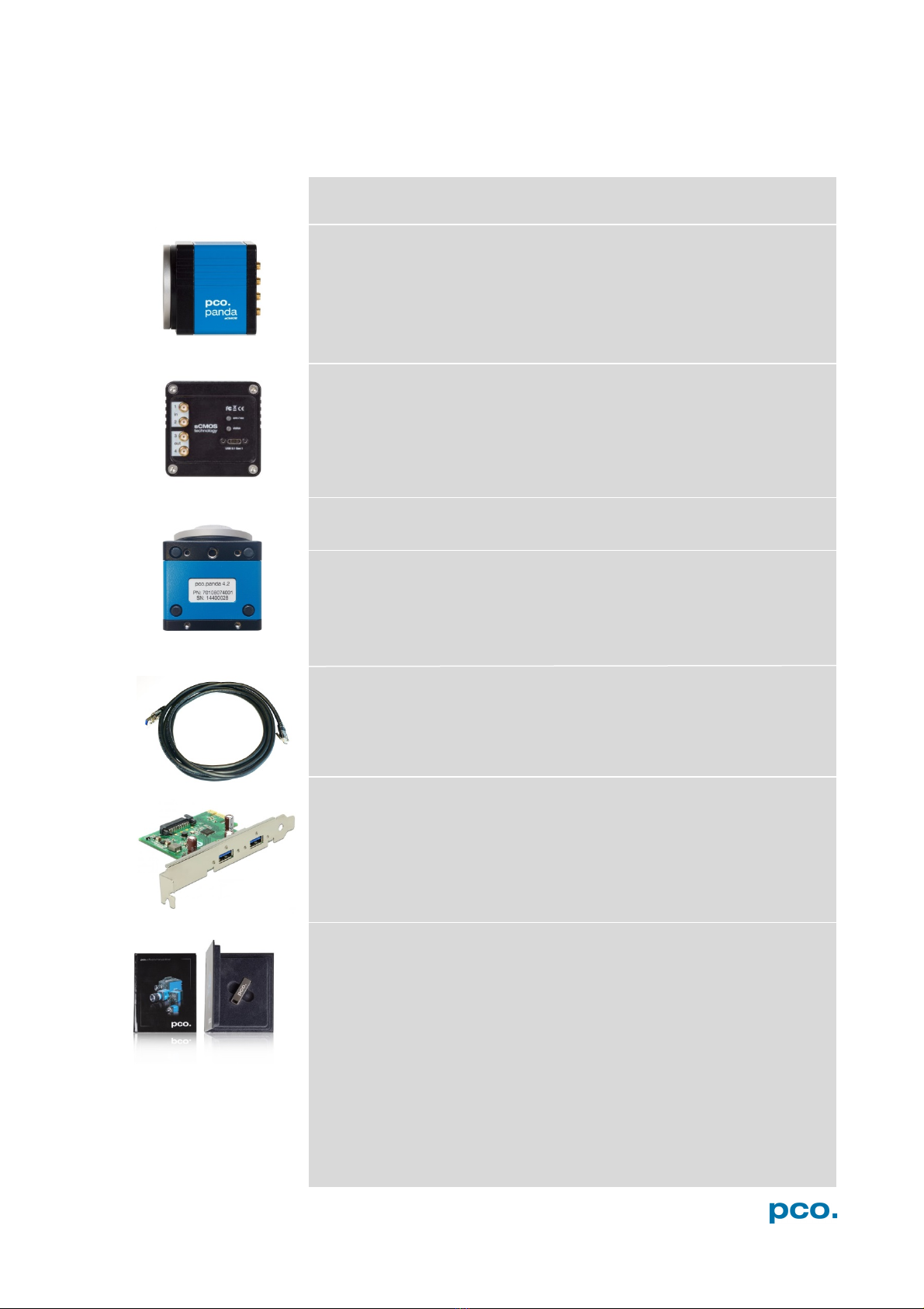
The camera system includes the following parts.
Camera
•C-mount optical connection
•F-mount adapter optional
•For standard C-mount / F-mount lenses and adapters
Rear Panel
•USB 3.1 Type C connector
•LED indicates camera status (see A1.4)
•SMA connectors
Serial Number Tag
Mounting Thread
•4x M4 (4)
•1/4"- 20 UNC (7)
USB 3.1 Cable
•USB Type A / USB Type C screwable cable
•Length 3 m
USB 3.1 Interface Card
•2x USB Type A socket
•PCI Express x1 V2.0
Digital Camera Tools (USB flash drive content)
•Camware: software for camera control & image acquisition
•Camera driver & tools
•Software Development Kit (SDK) & demo programs in C and C++
8
4. INSTALLATION
You find all necessary files on the accompanying USB flash drive.
You may also download the latest versions of our software, camera
driver and third party software drivers from our Website
(www.pco.de).
Minimum system requirements:
•Intel® Core™ i7
•Full-HD resolution display
•RAM > 8 GB DDR3
•USB 3.1 Gen1
•Windows 7 or higher
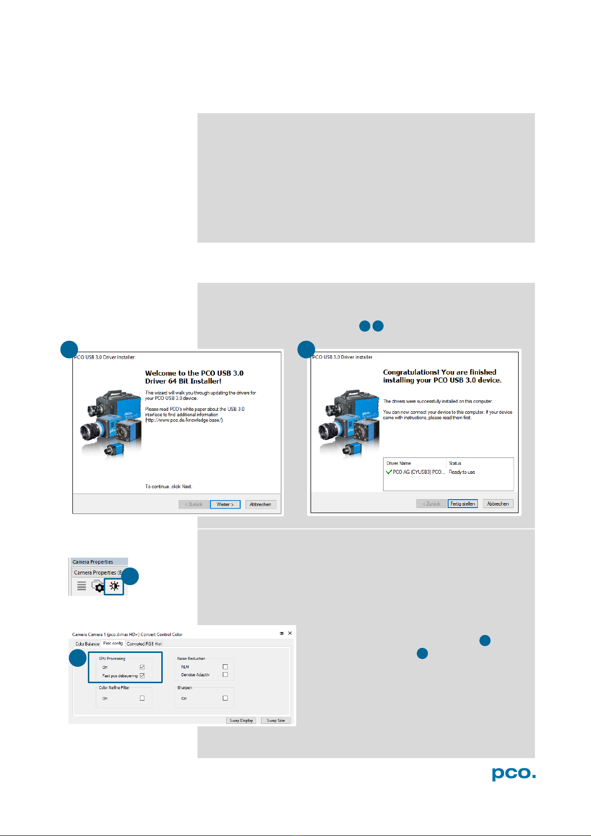
4.1 DRIVER
Install PCO USB 3.0 Driver
Always install the latest USB driver version. After these two screens
the driver is completely installed.
NVIDIA Cuda Driver
Only relevant if an NVIDIA graphics card is used! GPU Processing is
only working with NVIDIA graphics cards.
Update your NVIDIA driver for Camware 4. In case of an old driver
version GPU Processing is not working. Therefore image processing
is slow.
Check if GPU Processing is activated by having
a look into the Proc config settings in the
Convert Control window (see chapter 6.3.8).
If GPU Processing is disabled and greyed out,
update your NVIDIA driver.
3
4
3
4
1
2
1
2

9
4. INSTALLATION
4.2 CAMWARE
The Camware application software enables to control every camera
parameter or setting. Images can be displayed on a monitor and may
be downloaded and stored. The USB flash drive contains the
installation files for the software for latest Windows operating
systems in 32 & 64 bit.
After a successful installation, you find the program file Digital
Camera Toolbox in your program directory and a Camware 32 / 64
button on your desktop.
To uninstall the Camware program, use the software feature under
Windows’ system control.
Follow the Installation Wizard
•Install as admin to install to program folder, otherwise it is
installed only to user folder
•Choose install directory
•Choose components: select additional drivers (not
recommended)
•After the next two screens installation is complete
1
2
3
4
1
1
2
3
4
10
5. QUICK START
In order to get familiar with your new camera and software it might be
helpful, if you first aim at an object that is easy to focus and that can
be seen at standard light conditions.
5.1 PREPARATION
•Computer is turned on
•Installation is finished (see chapter 4)
•An appropriate lens is attached (remove cap) or the camera is
attached properly to the microscope, spectrograph or other
scientific device
•Camera is connected to the PC
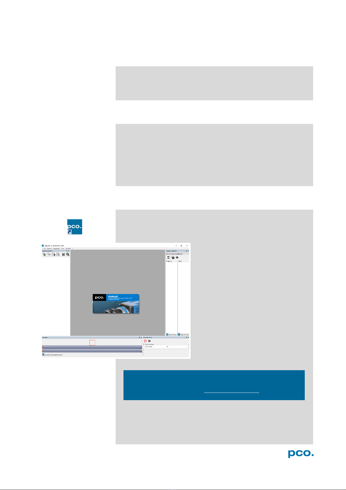
5.2 START
Start Camware and the graphical user interface starts up:
NOTE
Always install latest Camware version to be able to use full
function of your pco camera (www.pco.de/support).
11
5. QUICK START
7
6
2
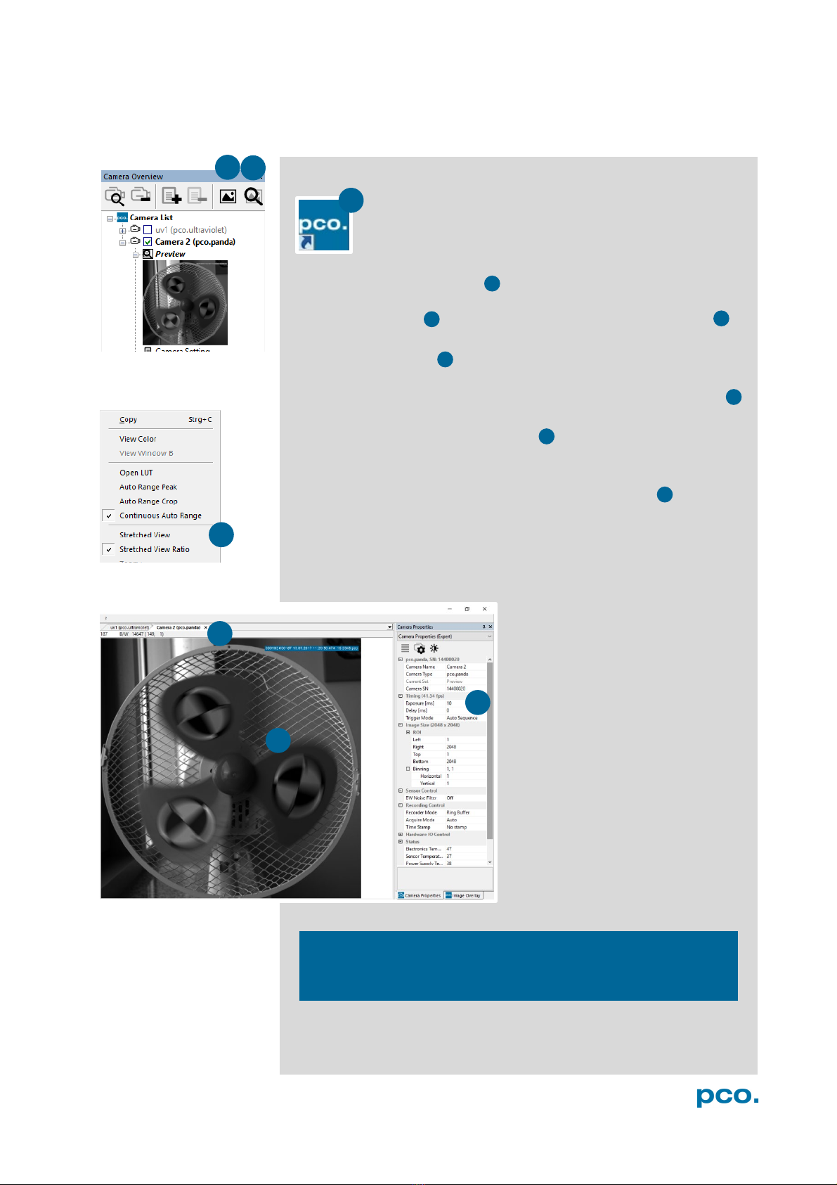
5.3 FIRST IMAGE
Follow the Instructions
•Camware must be started
•A View Window is shown automatically or open a new one
•Start Live Preview
•Right-click in the view window & apply Continuous Auto Range
•You may adjust Exposure time , aperture and focus of the
mounted lens
•Now you should clearly see the object in the window
To change Exposure time (e.g. the
image is still either too dark or too
bright), see chapter 6.3.1.
To record and save images, see
chapter 6.3.5 and chapter 6.9.2 for
detailed information.
NOTE
Live preview: useful for fast and easy camera adjustment and
focusing.
2
4
5
6
7
3
4
5
1
1
3

12
6. CAMWARE 4 SOFTWARE
PCO’s Camware is excellent software for camera control,
image acquisition and archiving of images in various file
formats. This chapter provides a detailed description of
all Camware functions.
Camware works with any kind of PCO camera. See PCO
website for the latest version of this software.
6.1 CHAPTER OVERVIEW
Chapter 6.2: cameras detected in Camware
6.2 Camera Overview/List
Preview / Connected cameras / Recording
profiles
Chapter 6.3: camera settings
6.3.1 Timing
Exposure Time / Trigger Modes
6.3.2 Rolling Shutter
Explanation / Timing
6.3.3 Image Size
ROI / Binning
6.3.4 Sensor Control
Offset Control / BW Noise Filter
6.3.5 Recording Control
Recorder Mode / Aquire Mode /
Timestamp
6.3.6 Status
Temperature
6.3.7 Hardware IO Control
Exposure Trigger / Aquire Enable / Status
Busy / Status Expos
6.3.8 Convert Control
Contrast / Saturation / Gamma…
Chapter 6.4 / 6.5 / 6.6 / 6.7 / 6.8 recording
6.4 Image Overlay
Overlay for recorded images
6.5 Recorder Tools
Record / Play / Settings
6.6 View Window
View Window Functions
6.7 Recorder (Images)
Preview Recorded Images
6.8 Settings Overview
Overview of all Parameter Settings / Auto
Save
Chapter 6.9software menus
6.9.1 Demo Mode
No camera connected
6.9.2 File Menu
Open / Save Raw / Export / Options
6.9.3 Camera Menu
Setup / Close / Rescan
Live Preview / Acquire Sequence
6.9.4 Acquisation Menu
Rec. Memory Settings
6.9.5
View Menu
New Window / Convert Control / Multi
Window / Toolbar / Application Look
6.9.6 Window Menu
New / Close / Split window
6.9.7 Help Menu
Logfiles / Support file / About
6.9.8 View window menu
Right-click: Zoom / Flip / Mirror / Rotate /
Line Profile / Properties
6.9.8 Additional features
Contrast / Short cut list
13
6. CAMWARE 4 SOFTWARE
2
3
4
5
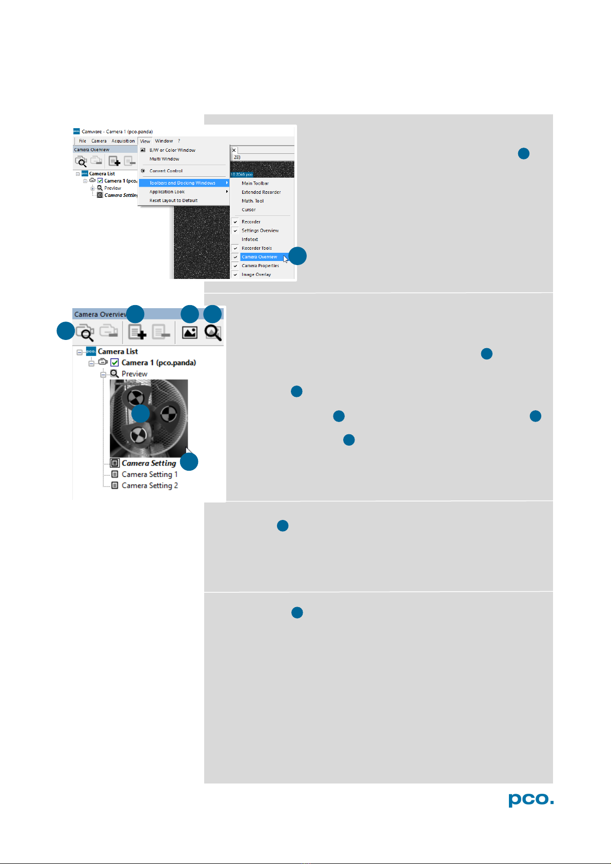
6.2 CAMERA OVERVIEW / LIST
If closed, the Camera Overview window can be
opened by selecting the View tab and Toolbars
and Docking Windows →Camera Overview .
Camera Overview
The Camera Overview window supports management of more
than one PCO cameras and displays a Camera List of the
connected ones. Camware is able to Scan Cameras 2 or close a
connected camera. It allows to define several different Camera
Settings for each camera (max. 30 sets per camera
→Add Set 3 ).
New View Windows 4 can be opened and the Live Preview 5
function started. When opened up, the Live Preview shows a
small Preview window 6 (always monochrome) integrated in the
Camera List.
Live Preview
Live Preview facilitates the aperture and focus adjustment, allowing
a first look at your object. During Live Preview Trigger Mode is set
to Auto Sequence.
Camera Setting
All presettings, such as resolution and frame rate, in the Camera
Properties (see 6.3) are saved to Camera Settings. Define different
Camera Settings with different Preferences in Camera Properties
for each of your experiments. Camera Settings can be switched at
any time (not during record) and copied to other cameras.
1
1
2
3
4
5
6
7
6
5
7

14
9
10
11
8
Link Preview Set to ‘Preview’
When Link Preview Set to ‘Preview’ is ticked the Preview is
always active with the set parameters when starting a Live
Preview 8 .
In case this function is deactivated, the Live Preview always
shows live images with the parameters of your active setting.
Setting a higher exposure time for Preview Setand linking it to
the Preview function is beneficial if Preview light conditions are
different from those in recording situations.
Copy Settings to Current Set
To copy e.g. Camera Setting 1 to Camera Setting 4, just drag and
drop Camera Setting 1 to Camera Setting 4 and Camware asks to
confirm it. It is possible to copy each setting to every camera.
Master Sets
This function facilitates the image acqusition with multiple
cameras. Defining two or more Master Sets allows easy
switching between different predefined settings for each camera
during an experiment. Each image acquisition or experiment can
be recorded with its own Master Set.
To display Master Sets, right-click in the Camera Overview
window and click Show Master Sets.
Define different Master Sets. Select individual Camera Settings
within each Master Set.
Functions:
Add Master Set or Remove Active Master .
Put it to active status by clicking on one of your sets .
Important Setting (for cameras without internal memory)
Memory Allocation Dialog
If you want to change the number of recorded images in
Camware, you have to open the Acquisition menu (see 6.9.4)
and choose Rec. Memory Settings.
This sets the number of images recorded in one sequence. The
maximum is defined by approved RAM size.
9
10
11
8
15
6. CAMWARE 4 SOFTWARE
1
2
3
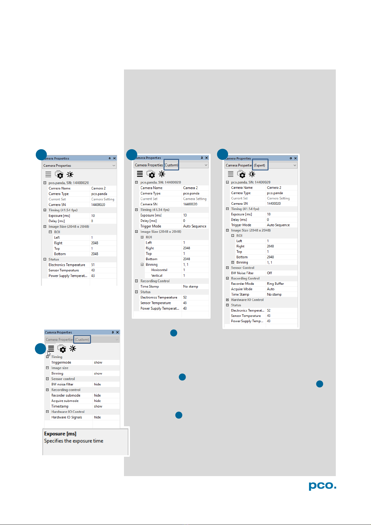
6.3 CAMERA PROPERTIES
The Camera Properties window in Camware is the main interface for
all camera settings. The active set selected within Camera List is
adjusted here.
The former main instance Camera Control (known from Camware
3.x) and the Convert Control (see 6.3.8) can be opened additionally.
Three view options with various functions can be selected: Basic,
Custom and Expert.
Basic mode 1 only shows camera name, type, set, serial number
and exposure time. In Basic mode the frame rate is always calculated
automatically based on the selected exposure time, i.e. if exposure
time is increased, frame rate decreases. It is recommended for
Camware beginners.
Custom mode shows several more setting possibilities and
functions are hidden or shown by the Custom Properties button.
Additional to the Basic mode, Trigger Mode, Image Size and
Recording control options are selectable.
Expert mode (for advanced users) shows all possible camera
feature settings.
An explanation for every setting is displayed below the Camera
Properties dialog.
1
2
4
3
4

16
2
1
6.3.1 TIMING
This chapter explains the timing of the pco.panda in Camware.
To basically understand the timing of the camera, read the
chapter 6.3.2 ROLLING SHUTTER.
Trigger Mode
In this context trigger means exposure trigger, i.e. the trigger
signal controls the exposure of a single image (light integration
time).
Auto Sequence:the camera optimizes the image recording to
achieve the best possible frame rate.
In the Auto Sequence mode, camera determines the highest
possible frame rate against set exposure time and the time
required for a frame readout.
Upon a start command the sequential recording starts and lasts
until a stop command.
Soft Trigger:single images are recorded with this Camware
command. A single image is acquired by pressing the Software
Trigger button, which appears after pressing the Record button (see
6.4 ). Other signals have no influence on this operating mode.
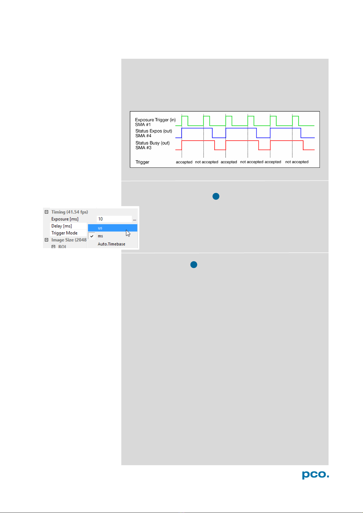
Ext. Exp. Start: in the External Exposure Start exposure control
mode, single image recording is started by the falling or rising edge of
the voltage signal at the SMA input #1(see 6.3.7). The frame rate
cannot be set, as the frame rate is defined by the frequency of the
external signal. However the predefined exposure time and ROI
settings affect the maximum possible frame rate.
The Status Busy signal at SMA #3 (see 6.3.7) indicates whether a
new trigger is accepted.
The maximum achievable frame rate in external trigger mode is lower
than in Auto Sequence mode, since the camera only starts exposing
after the readout of the previous image is completed.
Example calculation for exposure time 10 ms:
•Line time: 12.136 µs
•Readout time full resolution (readout time depends on vertical
resolution):
oImage size: 2048 x 2048 pixels
oReadout time: 2048 x 12.136 µs = 24.85 ms
•Calculation: 1 / (24.85 ms + 10 ms) = 28.69 fps
1
3
17
6. CAMWARE 4 SOFTWARE
If the trigger rate of the external signal is higher than the maximum
possible frame rate, every second trigger pulse is ignored. Therefore
the actual frame rate drops to half of the external trigger rate. If the
trigger rate is increased further, then only every third, every fourth etc.
trigger edge is accepted.
Exposure Time and Time-base
It is possible to change time-base from automatic to µs or ms. If
your input is out of the range of the camera, it is automatically
changed to the next possible setting. The exposure time and
delay time can be adjusted in steps of 10 μs. The jitter of the
actual exposure start edge is about 12 µs.
Maximum Frame Rate
Camware automatically calculates and displays the maximum
achievable frame rate based on the timing and ROI settings.
2
3

18
6.3.2 ROLLING SHUTTER
The pco.panda uses the rolling shutter mode. In this mode the pixel
reset and exposure start is carried out line by line. Each line has the
same exposure time, but a different start and end of exposure. Within
one line, the exposure starts simultaneously for all pixels.
The exposure time of each line starts with the corresponding reset of
the line. Then after a predefined time (exposure time), the exposure is
stopped. The light induced accumulated charge carriers of the pixels
in a line are recorded into memory in a low noise (readout) mode. This
way the content of the pixels is assembled in the memory to form the
complete image.
The diagram shows different signal timing settings (see chapter
6.3.7). During Show common time of ‘All Lines’ the image sensor is
completely exposed to light. The labels Show time of ‘First Line’
and ‘Last Line’ are the setting for the first / last exposed line and
Show overall time of ‘All Lines’ for the entire exposure period.
There are two different timing cases for rolling shutter mode, which
are explained on the following pages:
•exposure time > sensor readout time
•exposure time < sensor readout time
Rolling Shutter General Timing Diagram
Timing
Camera
Exposure time
Delay time
Line time
pco.panda 4.2
USB 3.1 10 µs … 5 s 0 … 5 s 12.136 µs
NOTE
The
exposure and
delay time can be
adjusted in steps of
one line time.
19
6. CAMWARE 4 SOFTWARE
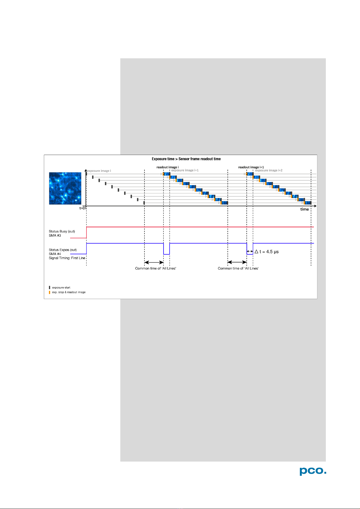
Exposure time > Sensor frame readout time
In case the required exposure time is longer than the frame readout
time, the image sensor is completely exposed to light for some time
(Show common time of ‘All Lines’ also see General Timing
Diagram). In case of a triggered flash illumination, this would be the
best moment to illuminate the image sensor. The hardware signal for
the time Show common time of ‘All Lines’ is available on connector
#4 (see 6.3.7).
This is an example timing diagram for Trigger Mode Auto
Sequence, SMA explanation see 6.3.7
20
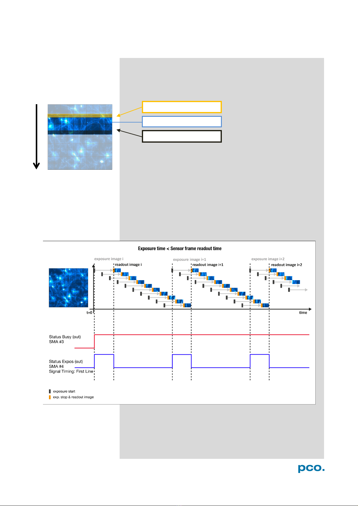
Exposure time < Sensor frame readout time
In case the required exposure time is shorter than the frame readout
time, the image is readout through an exposure band moving from
the top to the bottom of the sensor.
For example the shortest exposure time in rolling shutter is 10 µs for
the pco.panda 4.2.
The band of simultaneous exposure is in this case (smallest possible
height) at full resolution:
For example: pco.panda 4.2: 10 µs / 12.136 µs (line time) = 1 →
number of simultaneous lines.
This is an example timing diagram for Trigger Mode Auto
Sequence, SMA explanation see 6.3.7
exposure stop & readout
reset & exposure start
band of simultaneous exposures
Other manuals for pco.panda 4.2
2
Table of contents
Other Pco Digital Camera manuals


