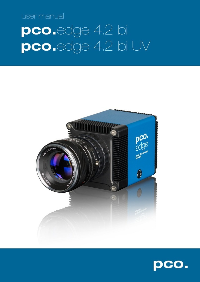
Pco edge 26 User manual

pco.
edge 26
pco.
user manual

PCO asks you to carefully read and follow the instructions in this
manual before using the pco.edge camera system.
For any questions or comments, contact us at PCO.
telephone +49 (0) 9441 2005 50
fax +49 (0) 9441 2005 20
email [email protected]
postal address PCO AG
Donaupark 11
93309 Kelheim, Germany
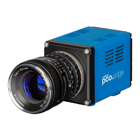
The cover photo shows a real-world use of a PCO camera system.
The lens is sold separately.
Released: Jan 2020 © PCO AG
pco.edge 26 User Manual V1.00 © PCO AG, Germany
This work is licensed under the Creative Commons Attribution-
NoDerivatives 4.0 International License. To view a copy of this
license, visit http://creativecommons.org/licenses/by-nd/4.0/ or
send a letter to Creative Commons, PO Box 1866, Mountain View,
CA 94042, USA.

3
1. INTRODUCTION 4
1.1 INTENDED USE 4
1.2 CONVENTIONS 4
2. SAFETY INSTRUCTIONS 5
3. SYSTEM COMPONENTS 6
4. INSTALLATION 8
4.1 DRIVER 8
4.2 CAMWARE SOFTWARE 9
5. QUICK START 10
5.1 PREPARATION 10
5.2 START 10
5.3 FIRST IMAGE 11
6. GLOBAL SHUTTER 12
7. CAMWARE 4 SOFTWARE 14
7.1 HARDWARE IO CONTROL 14
APPENDIX 16
A1 TECHNICAL DATA 17
A1.1 DATA SHEET 17
A1.2 MECHANICAL DIMENSIONS 18
A1.3 REAR PANEL 19
A2 HARDWARE MOUNTING 20
A2.1 USB CARD INSTALLATION 20
A2.2 CABLE MOUNTING 21
A3 F-MOUNT ADAPTER 22
A3.1 PCO F-MOUNT ADAPTER 22
A3.2 CHANGE FROM F-MOUNT TO C-MOUNT 23
A4 WATER COOLING OPTION PCO.AQUAMATIC II 24
A4.1 SYSTEM COMPONENTS 24
A4.2 FIRST TIME INSTALLATION 25
A4.3 OPERATION 26
A4.4 DIMENSIONS 27
A4.5 USING YOUR OWN COOLING SYSTEM 27
A5 CUSTOMER SERVICE 28
A5.1 SERVICE 28
A5.2 MAINTENANCE 28
A5.3 RECYCLING 28
A5.4 TROUBLESHOOTING 29
A6 INDEX 30
ABOUT PCO 31
TABLE OF CONTENTS

4
1. INTRODUCTION
The pco.edge 26
Welcome to the pco.edge 26 system. This manual should help
you to familiarize yourself with the camera and its functions. If you
have any questions, please contact PCO directly.
Main Features
•True charge domain global shutter
•Ultra high resolution: 5120 x 5120 pixel
•Exposure time: 5 µs ... 60 s
•Pixel size (h x v): 2.5 µm x 2.5 µm
•Dynamic range 66 db
•Compact design
•Adjustable: from - 20 °C to + 20 °C peltier with forced air
(fan) and water cooling
•Up to 72 % quantum efficiency
•USB 3.1 Gen 1 data interface
1.1 INTENDED USE
This camera system is designed for use by technicians, engineers
and scientists. It is a scientific measuring instrument, which also
provides images.
The camera may only be used according to the instructions of this
manual. Operator agrees to respect the disclosures and operating
conditions in these operating instructions. To ensure safe use,
unauthorized modifications and changes to the device are forbidden.
1.2 CONVENTIONS
The following typographic conventions are used in this manual:
bold italics
Terms that can be found in the software pco.camware
Features
Heading within a chapter
A1.3
Bold chapter: hyperlink to a chapter
Numbers direct to corresponding function
Notes that must be observed
1 1

5
2. SAFETY INSTRUCTIONS
Read the safety instructions completely. Failure to follow them can
result in injury or death.
DAMAGED POWER CABLE OR POWER PLUG
Mortal danger due to electric shock.
Check the power cable for damage each time the camera is
used.
ELECTRIC SHOCK WARNING DUE TO VOLTAGE PARTS INSIDE
Risk of injury due to electric shock.
Never slide any items through slits or holes into the camera.
MOISTURE
Risk of injury due to electric shock if moisture enters the camera.
To avoid the risk of water condensation, protect the camera
against extreme changes of ambient temperature.
TRIPPING HAZARD
Risk of injury from tripping over loose cables.
Never position the cable in such a way as to become a
tripping hazard.
HUMIDITY, DUST OR RADIATION
Humidity, dust or X-rays can damage the camera.
Never operate the camera in humid or dusty environments
or in places with high levels of x-ray radiation.
VIBRATION
Camera must be firmly mounted and protected against strong
shocks or vibrations to avoid damage.
Use the camera's mounting threads to secure it.
LENS MOUNTING
Screw in the lens gently to avoid thread damage.
Use minimal force when attaching a lens to the camera to
protect the lens connector thread from damage.
LIQUIDS DAMAGE CAMERA
If liquids have penetrated the device:
Switch the camera off immediately, detach it from power and
contact PCO's customer support.
DAMAGED CAMERA HOUSING
If the camera has been dropped or the camera body is damaged:
Switch the camera off immediately, detach it from power and
contact PCO's customer support.
IF CAMERA IS NOT WORKING PROPERLY
If the troubleshooting steps in this manual are unsuccessful:
Switch the camera off immediately, detach it from power and
contact PCO's customer support.
NOTICE
NOTICE
NOTICE
NOTICE
NOTICE
NOTICE
WARNING
CAUTION
CAUTION
DANGER
N

6
3. SYSTEM COMPONENTS
The camera system includes the following parts.
Camera
•F-mount / C-mount optical connection
•For standard C-mount / F-mount lenses and adapters
Rear Panel
•USB 3.1 Type C connector
•LED indicates camera status (see A1.3)
•SMA connectors
•Power connector
Serial Number Tag
Mounting Thread
•1x 1/4"- 20 UNC
USB 3.1 Cable
•USB Type A / USB Type C screwable cable
•Length 3 m
USB 3.0 / 3.1 Gen1 Interface Card
•2x USB Type A socket
•PCI Express x1 V2.0
Power Supply & Power Cord
•Output: 24 VDC / 36W / 1.5A
•Connector: Lemo FGG.0B
•Voltage input: 115 VAC - 230 VAC; IEC 60320 C14 plug
•Power cord IEC 60320 C13

7
Digital Camera Tools (USB flash drive content)
•pco.camware: software for camera control & image acquisition
•Camera driver & tools
•Software Development Kit (SDK) & demo programs in C and C++

8
4. INSTALLATION
All necessary files can be found on the accompanying USB flash
drive. You may also download the latest versions of our software,
camera driver and third party software drivers from our Website
(www.pco.de).
Minimum system requirements:
•Intel® Core™ i7
•Full-HD resolution display
•RAM > 8 GB DDR3
•
USB 3.1 Gen1
•Windows 7 or higher
4.1 DRIVER
Install PCO USB 3.0/3.1 Driver
Always install the latest USB driver version. Install the driver from
screen . You will see screen after the driver is successfully
installed.
NVIDIA Cuda Driver
This is only relevant if an NVIDIA graphics card is used! GPU
Processing only functions with NVIDIA graphics cards.
Update your NVIDIA driver for pco.camware. If an old driver version is
installed, GPU Processing will not function, and image processing
will be slow.
Check if GPU Processing is activated from the
Proc config settings in the Convert Control
window (see pco.camware manual).
If GPU Processing is disabled and greyed out,
update your NVIDIA driver.
1 2
3
1
4
2
4
3

9
4.2 CAMWARE SOFTWARE
The pco.camware software controls every camera parameter or
setting. Images can be displayed on a monitor and may be
downloaded and stored. The USB flash drive contains the installation
files for Windows operating systems in 32 & 64 bit.
After a successful installation, you will find the program file Digital
Camera Toolbox in your program directory and a pco.camware 32 /
64 button on your desktop.
To uninstall the pco.camware program, navigate to Windows’ Add or
remove programs from system settings.
Follow the Installation Wizard
•Install as admin to install to program folder, otherwise it is
installed only to user folder
•Choose install directory
•Choose components: select additional drivers (not recommended
for pco.edge 26)and select Install
•Installation is complete
1
2
3
4
1
1 2
3 4

10
5. QUICK START
To familiarize yourself with your new camera and software it might be
helpful to first aim at an object that is easy to focus on and that can
be seen in standard light conditions.
5.1 PREPARATION
Before beginning, ensure that:
•Computer is turned on
•Installation is finished (see chapter 4)
•An appropriate lens is attached (remove cap) or the camera is
attached properly to the microscope, spectrograph or other
scientific device
•Camera is connected to the PC
5.2 START
Start pco.camware to begin working with the graphical user interface:
NOTE
Always install the latest version of pco.camware to access full
function of your camera (www.pco.de/support).

11
7
6
2
5.3 FIRST IMAGE
Follow the Instructions
•Start pco.camware
•A View Window is shown automatically or open a new one
•Start Live Preview
•Right-click in the view window & apply Continuous Auto Range
•You may adjust Exposure time , aperture and focus of the
mounted lens
•You should clearly see the object in the window
To change Exposure time (e.g., the image is still
either too dark or too bright) and to record and
save images, see pco.camware manual for
detailed information.
NOTE
Live preview: useful for fast and easy camera adjustment and
focusing.
2
4 5
6
7
3 4
5
1
1
3

12
6. GLOBAL SHUTTER
The pco.edge 26 uses the global shutter mode for image acquisition.
First, all pixels are globally reset and its reset values are stored
internally on the sensor. The image exposure starts. After exposure
and readout, the sensor completes the correlated double sampling
(CDS). During the readout phase, a new exposure can start.
Timing
The exposure and delay time can be adjusted in a step size of 30 µs.
Camera Exposure time Delay time
pco.edge 26
20 µs … 60 ms
0 µs … 1 s

13

14
1
2
3
4
7. CAMWARE 4 SOFTWARE
This chapter contains only camera-specific additions to the
pco.camware manual. All main functions and explanations can be
found in the pco.camware manual.
7.1 HARDWARE IO CONTROL
Settings can be changed with a drop-down
menu.
Exposure Trigger
If On, a signal for External Exposure Start Trigger Mode is
accepted at the Exposure Trigger SMA input #1.
Exposure Trigger: On; Off
Signal Polarity: Rising; Falling
Acquire Enable
If On, a signal for Acquire Mode is accepted at the Acquire Enable
SMA input #2.
Acquire Enable: On; Off
Signal Polarity: High; Low
Status Busy
If On, a signal indicating busy status is provided at the Status Busy
output. Once an acceptable trigger edge is received, ‘busy’ goes to
status high. As soon as ‘busy’ goes low again, a new trigger edge is
accepted.
Status Busy: On; Off
Signal Polarity: High; Low
Status Expos
If On, a signal indicating exposure or line status is given at the status
output. Status Expos indicates the actual exposure window for one
frame.
Select IO Signal: Status Expos;
Signal timing:Show time of ‘First Line’; Show common time of ‘All
lines’; Show time of ‘Last line’; Show overall time of ‘All lines’
Status Expos: On; Off
Signal Polarity: High; Low
2
1
3
4
1 2 3 4

15
Enabling and Polarity of IO Signals
The polarity of the input and output signals indicating their active
states is selectable (positive or negative logic).
The polarity of level-sensitive signals can be set to High (positive
logic) or Low (negative logic).
The polarity of edge-sensitive signals can be set to Rising (positive
logic) or Falling (negative logic).

16
APPENDIX
APPENDIX
A1 TECHNICAL DATA 16
A1.1 DATA SHEET 17
A1.2 QUANTUM EFFICIENCY CURVE 17
A1.3 MECHANICAL DIMENSIONS 18
A2 HARDWARE MOUNTING 19
A2.1 USB CARD INSTALLATION 19
A2.2 MOUNTING OF THE PCO.EDGE 26 21
A3 F-MOUNT ADAPTER 22
A3.1 PCO F-MOUNT ADAPTER 22
A3.2 CHANGE FROM C-MOUNT TO F-MOUNT 23
A4 WATER COOLING OPTION PCO.AQUAMATIC II 24
A4.1 SYSTEM COMPONENTS 24
A4.2 FIRST TIME INSTALLATION 25
A4.3 OPERATION 26
A4.4 DIMENSIONS 27
A4.5 YOUR OWN COOLING SYSTEM 27
A5 CUSTOMER SERVICE 28
A5.1 SERVICE 28
A5.2 MAINTENANCE 28
A5.3 RECYCLING 28
A5.4 TROUBLESHOOTING 29
A6 INDEX 29
ABOUT PCO 31

17
A1 TECHNICAL DATA
A1 TECHNICAL DATA
A1.1 DATA SHEET
Image sensor
pco.edge 26
Type of sensor
customized sCMOS
Resolution (h x v)
5120 x 5120 pixel
Pixel size (h x v)
2.5 µm x 2.5 µm
Sensor format / diagonal
12.8 x 12.8 mm / 18.1 mm
Shutter mode
Global/Snapshot Shutter (GS)
MTF
200 lp/mm (theoretical)
Camera
Frame rate
7.1 fps @ full resolution
Exposure / shutter time
5 µs ... 60 ms
Dynamic range A/D
12 bit
Binning (h x v)
1x1 ... 4x4
Cooling method
adjustable: from -20°C to +20°C
peltier with forced air (fan) and water
cooling. Calibration setpoint: -10°C
Trigger input signals
frame trigger, sequence trigger,
programmable input (SMA connectors)
Trigger output signals
exposure, busy, programmable output
(SMA connectors)
Data interface
USB 3.1 Gen1
Timestamp
in image (1 µs resolution)
General
Power delivery
power over USB 3.1 Gen1 and power
connector (24 VDC +/- 10%)
Power consumption
typ. 4.5 W over USB 3.1 Gen 1 and
typ. 10.0 W (max. 22.0 W) overpower
connector
Weight
970 g
Operating temperature
+10°C ... +40°C
Operating humidity range
10% ... 80% (non-condensing)
Storing temperature range
-10°C ... +60°C
Optical interface
F-mount, C-mount
CE / FCC certified
yes
ROI step sizes
Horizontal steps
32 pixel steps
Vertical steps
8 pixel steps
Minimum ROI
64 x 16 pixels
Subject to change, refer to current data sheet available on our website.

18
A1 TECHNICAL DATA
A1.2 MECHANICAL DIMENSIONS
All dimensions are in millimeters.
2D and 3D technical drawings are available on our website.
3D step files and further technical drawings are available on request.

19
A1 TECHNICAL DATA
A1.3 REAR PANEL
Status LEDs
(LED1: green / red; LED 2: orange)
Color
Description
Red / green continuous
Camera is booting
Green
Camera is ready for operation
Orange continuous
Arm camera / rec state off
Orange blinking
Recording on
Red continuous
Error
Interface Connector
USB 3.1 plug Type-C (screwable)
SMA Inputs
(see chapter 7)
Input (1=Exposure Trigger; 2=Acquire Enable)
Type
Digital
Level
3.3 V LVTTL (5 V tolerant)
Coupling
DC
Impedance
1 kΩ
Slew rate
> 1 V/ms
SMA Outputs
(see chapter 7)
Output (3=Status Busy; 4=Status Expos)
Type
Digital
Level
3.3 V LVTTL
Coupling
DC
Load current
Max. 100 mA
Power Input
LEMO socket ECG.0B.302.CLV
Pin1
ground
Pin2
VCC 12 V … 24 V
Appropriate Lemo plug: FGG.0B.302.CLAD52Z
Power Switch
1
4
3
2
5
3
1 4
Pin1 Pin2
6
5
6 2
3 4

20
A2 HARDWARE MOUNTING
A2 HARDWARE MOUNTING
These instructions will show how to mount the pco.edge 26 camera
system.
A2.1 USB CARD INSTALLATION
An external USB 3.0 / 3.1 Gen1 host controller card comes with each
pco.edge 26 camera.
Hardware Installation
First shut down your computer and install the USB 3.0 / 3.1 Gen1
host controller card. Hardware installation must be performed by a
technician, because high voltages can run through the device.
ELECTRIC SHOCK WARNING DUE TO VOLTAGE PARTS INSIDE
Risk of injury due to electrical shock.
Always pull the main plug before opening the computer.
Driver Installation Instructions
•Within the provided installation files USB_HBA, open the folder
U3X4-PCIE4XE101, U3X4-PCIE1XE101, U3-PCIE1XG202.
•Open the subfolder Driver and run RENESAS-USB3-Host-Driver-
30230-setup.exe.
•If your current OS is Win 7 / 8 and the User Account Control is
enabled, a dialog prompts whether you wish to start the setup:
accept with Yes.
•System begins by preparing for installation.
•The software components are copied automatically.
•Installation is complete and the Delock USB 3.0 / 3.1 Gen1
extension card is ready for use.
1
1
3
2
2 3
WARNING
NOTE
In multi-camera
operation, each
pco.
edge 26
camera needs its
own USB host
controller card.
Table of contents
Other Pco Digital Camera manuals
