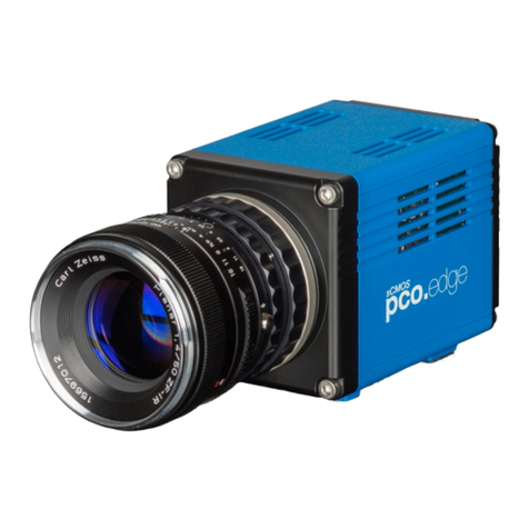
Pco dicam C1 User manual

pco.
dicam C1
pco.dicam C4
pco.
user manual

PCO asks you to read this manual carefully before using the
pco.dicam C1 / C4 camera system and follow the instructions.
Contact us for further questions or comments.
telephone +49 (0) 9441 2005 50
fax +49 (0) 9441 2005 20
email info@pco.de
postal address PCO AG
Donaupark 11
93309 Kelheim, Germany
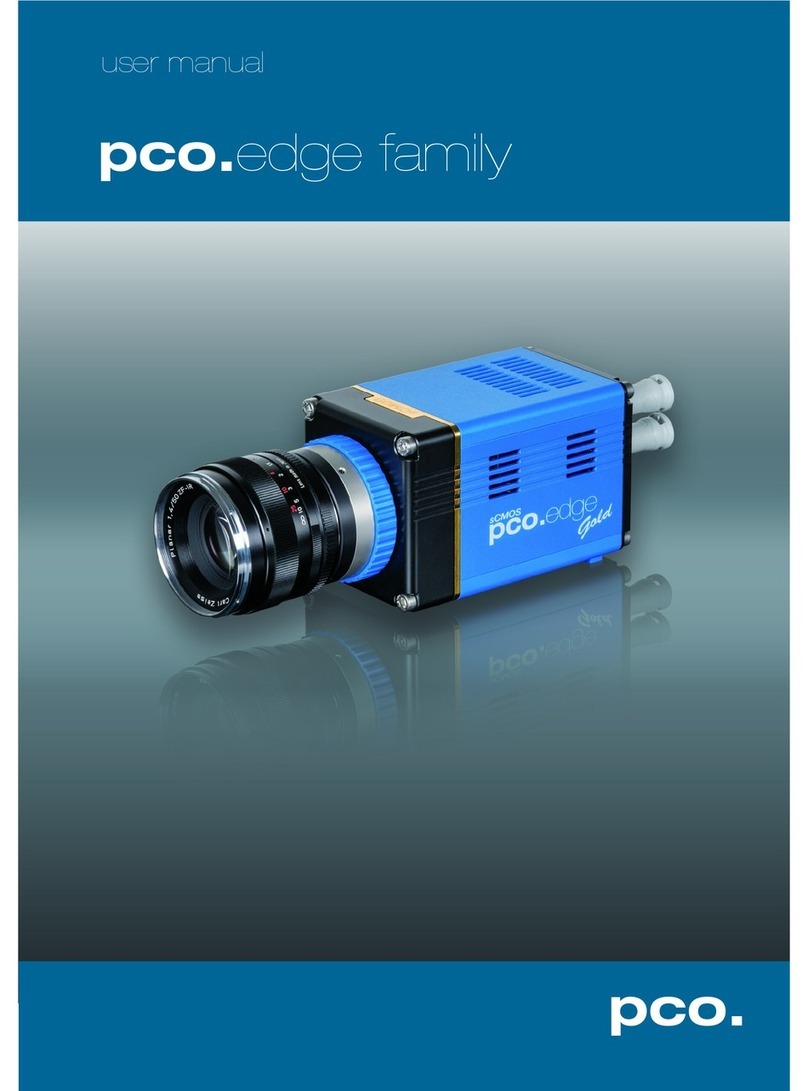
The cover picture shows a typical pco.dicam C1camera.
The lens issold separately.
Copyright © 2019PCO AG (called PCO hereinafter), Kelheim, Germany. All
rights reserved. PCO assumes no responsibility for errors or omissions in
these materials. These materials are provided as is without warranty of any
kind, either expressed or implied, including but not limited to, the implied
warranties of merchantability, fitness for a particular purpose, or non-
infringement. PCO further does not warrant the accuracy or completeness of
the information, text, graphics, links or other items contained within these
materials. PCO shall not be liable for any special, indirect, incidental, or
consequential damages, including without limitation, lost revenues or lost
profits, which may result from the use of these materials. The information is
subject to change without notice and does not represent a commitment on
the part of PCO in the future. PCO hereby authorizes you to copy documents
for non –commercial use within your organization only. In consideration of
this authorization, you agree that any copy of these documents, which you
make, shall retain all copyright and other proprietary notices contained
herein. Each individual document published by PCO may contain other
proprietary notices and copyright information relating to that individual
document. Nothing contained herein shall be construed as conferring by
implication or otherwise any license or right under any patent or trademark of
PCO or any third party. Except as expressly provided, above nothing
contained herein shall be construed as conferring any license or right under
any PCO copyright. Note that any product, process, or technology in this
document may be the subject of other intellectual property rights reserved by
PCO, and may not be licensed hereunder.
Released: September 2019 ©PCO AG
pco.dicam C1/C4 user manual V2.00 © PCO AG, Germany

3
TABLE OF CONTENTS
1. INTRODUCTION 5
1.1 INTENDED USE 5
1.2 FORESEEABLE MISSUSE 5
1.3 SCHEMATIC SKETCH 6
2. SAFETY INSTRUCTIONS 7
2.1 SAFE USE OF IMAGE INTENSIFIER 8
3. SYSTEM COMPONENTS 9
3.1 SYSTEM COMPONENTS PCO.DICAM C1 9
3.2 SYSTEM COMPONENTS PCO.DICAM C4 10
4. INSTALLATION 11
4.1 DRIVER 11
4.2 CAMWARE 12
5. FIRST START 13
5.1 PREPARATION 13
5.2 START 13
5.3 FIRST IMAGE 14
6. TIMING PCO.DICAM C1 15
6.1 SINGLE IMAGE MODE 15
6.2 DOUBLE IMAGE MODE 17
7. TIMING PCO.DICAM C4 20
7.1 MASTER VS INDIVIDUAL CHANNEL TRIGGER 20
7.2 SINGLE IMAGE MODE 4 CHANNELS 21
7.3 DOUBLE IMAGE MODE 4 CHANNELS 22
8. CAMWARE SOFTWARE 23
8.1 TIMING 23
8.2 SENSOR CONTROL 23
8.3 INTENSIFIER CONTROL 24
8.4 HARDWARE I/O CONTROL PCO.DICAM C1 26
8.5 HARDWARE I/O CONTROL PCO.DICAM C4 27
9. SPECIAL FEATURES PCO.DICAM C4 28
9.1 COMMON TIME PROPERTIES 28
9.1.1 SINGLE IMAGE MODE 30
9.1.2 DOUBLE IMAGE MODE 31
9.1.3 WITHOUT COMMON SETTINGS 32
9.2 CAMERA MENU 33
9.3 MATCHING THE 4 IMAGE INTENSIFIERS 34
TOP

4
APPENDIX 35
A1 TECHNICAL DATA PCO.DICAM C1 36
A1.1 MECHANICAL DIMENSIONS 36
A1.2 SPECIFICATIONS 37
A1.3 REAR PANEL 39
A2 TECHNICAL DATA PCO.DICAM C4 41
A2.1 MECHANICAL DIMENSIONS 41
A2.2 COLLIMATING LENS MOUNTING 44
A2.3 SPECIFICATIONS 45
A2.4 REAR PANEL 47
A3 ADAPTER / ACCESSORIES 49
A3.1 PCO.TRIGGER UNIT 49
A3.2 PCO F-MOUNT ADAPTER 51
A3.3 CHANGE FROM F-MOUNT TO C-MOUNT 52
A4 KAYA FRAME GRABBER INSTALLATION 53
A4.1 INTRODUCTION 53
A4.2 SYSTEM REQUIREMENTS 53
A4.3 SAFETY INSTRUCTIONS 53
A4.4 FRAME GRABBER INSTALLATION 54
A4.5 VISION POINT SOFTWARE 55
A4.6 UPDATE FIRMWARE OF THE GRABBER 56
A5 IMAGE FILE FORMATS 57
A6 CUSTOMER SERVICE 59
A6.1 SERVICE 59
A6.2 MAINTENANCE 59
A6.3 RECYCLING 59
A6.4 TROUBLE SHOOTING 60
A7 COUNTRY SPECIFIC SPECIFICATION 61
A8 INDEX 62
ABOUT PCO 63

5
1 INTRODUCTION
1. INTRODUCTION
Advantages of the pco.dicam
After more than 30 years of experience with image intensified
cameras, we are proud to introduce the new pco.dicam C1 and
pco.dicam C4.
The pco.dicam is the first camera system with image intensifier
technology that harnesses the full power of the sCMOS sensor.
Unique is the optical connection of the high-resolution 25 mm image
intensifier to the 16 bit sCMOS sensor via an efficient tandem lens.
Individual photons are detected using the shortest exposure times.
10G fibre optic data interface (Camera Link HS) guarantees
uncompressed and secure data transfer. The latest standard of high-
performance data interfaces enables the bridging of long distances
via fiber optic cable.
Main Features
•intensified sCMOS technology
•exposure times down to 4 ns
•double shutter mode with 300 ns / 500 ns interframing time
(depending on your pco.dicam)
•optical coupling via ultra-speed tandem lens
•up to 3.4 GByte/s with 4 x 10 G fibre optic data interface
(Camera Link HS) (pco.dicam C4)
•2048 x 2048 pixels
1.1 INTENDED USE
This camera system is designed for use by technicians, engineers
and scientists. It is a scientific measuring instrument, which provides
images. The camera may only be used according to the instructions
of this manual. Provisions, limitations and operating conditions stated
in this manual must be respected. Unauthorized modifications and
alterations of the device are forbidden for safety reasons.
1.2 FORESEEABLE MISSUSE
•To avoid damages or loss of quality, the camera should not be
operated with a too high light input →A few milliseconds or even
microseconds may be sufficient to damage the photocathode if
the light source is powerful enough.
•Do not open lens cap during day light or with external light
source!
•If damaged, a complete replacement of the image intensifier is
necessary (very expensive)
•Read the safety instructions for use of image intensifier
chapter 2.1

6
1
2
3
4
5
6
1.3 SCHEMATIC SKETCH
Layout of an intensified PCO camera (single channel)
•Objective lens (not included)
•Image intensifier
•Tandem lens optical coupling system
•sCMOS image sensor
•Camera system
•Camera Link HS interface
•Camera Link HS frame grabber card
Find further information on structure and function in the pco.dicam
whitepaper.
1
2
3
4
5
6
7
7

7
2 SAFETY INSTRUCTIONS
2. SAFETY INSTRUCTIONS
CLASS 1 LASER PRODUCT
Risk of injury due to dazzle.
Do not point the laser beam at persons.
Do not look into the laser beam or at direct reflexes.
Manipulations of the laser device are not allowed.
DAMAGED POWER CABLE OR POWER PLUG
Danger to life due to electric shock.
Each time the camera is used, check the power cable for
damage.
ELECTRIC SHOCK WARNING DUE TO VOLTAGE PARTS INSIDE
Risk of injury due to electric shock.
Never slide any items through slits or holes into the camera.
MOISTURE
Risk of injury due to electric shock if moisture enters the camera.
To avoid the risk of water condensation, protect the camera
against extreme changes of ambient temperature.
TRIPPING HAZARD
Risk of injury from tripping over loose cables.
Never position the cable in a way that it could become a
tripping hazard.
HUMIDITY, DUST OR RADIATION
Humidity, dust or X-rays could damage the camera.
Never operate the camera in humid or dusty environments
or in places with high levels of X-ray radiation.
SHOCK & VIBRATION
To avoid damaging the camera it must be firmly mounted and
protected against strong shocks or vibrations.
Use the camera's mounting threads to secure it.
LENS MOUNTING
Do not force the lens onto the camera.
Mount or screw in the lens gently to avoid thread or mount
damage.
LIQUIDS DAMAGE CAMERA
If liquids have penetrated the device.
Switch the camera off immediately, detach it from power and
contact PCO's customer support.
DAMAGED CAMERA HOUSING
If the camera has been dropped or the camera’s housing is
damaged.
Switch the camera off immediately, detach it from power and
contact PCO's customer support.
NOTICE
NOTICE
NOTICE
NOTICE
NOTICE
DANGER
WARNING
CAUTION
CAUTION

8
2.1 SAFE USE OF IMAGE INTENSIFIER
LIGHT DAMAGES IMAGE INTENSIFIER
Too much light input during exposure time (gate=ON) lowers the
lifetime of the image intensifier.
Be careful with all kinds of light sources, a few milliseconds
can be enough to damage the image intensifier irreversibly.
Working with Image Intensifiers: Safety Instructions
The camera contains a highly sensitive image intensifier. To avoid
damages or loss of quality, the camera should not be operated with
too high light input. The photocathode’s lifetime and its loss of
sensitivity depend directly on the amount of light impinging on it
during exposure time. A few milliseconds or even microseconds of
exposure time may be sufficient to damage the photocathode if the
light source is powerful enough. The photocathode is a few µm thin
layer of a photo sensitive material. It absorbs photons and in turn
generates photoelectrons for amplification in the Micro Channel Plate
(MCP). In case the photoelectron generation rate is too high due to
intense light input, the photocathode might be eroded. In extreme
cases the layer completely wears off and there a black spot appears.
The photocathode is now ‘blind’ and there is no remedy except
replacing the complete image intensifier tube. Bright light sources,
e.g. lamps or daylight (for example while adjusting or focusing the
camera) in a long exposure operation mode can permanently damage
the photocathode, even when a monitor does not show any picture
(if, for instance the Intensifier Voltage MCP-Gain is set to minimum).
Since the MCP is behind the photocathode, changing the MCP-Gain
does not affect the load of the photocathode. It is a wrong conclusion
to assume lower MCP-Gain would save the photocathode in an
overexposed scene. The opposite is true.
Therefore for a safe camera operation we recommend to start with a
nearly closed iris (high f-stop, e. g. 22), short exposure time and
maximum MCP-Gain value (Image Intensifier Voltage set to
maximum). If no image is visible to yield an image the exposure time
may be carefully increased or the iris opened step by step.
If the camera is not in use replace the cap in front of the lens or
intensifier.
Operational Lifetime Values
The manufacturer of the image intensifier tube specifies durability for
continuous, non-gated operation only:
The half-life of the image intensifier (time taken for a 50% decrease in
sensitivity) is approximately 2000 hours at a light input of 1 mlx. 10-
times higher light input reduces the half-life to approximately 200
hours.
In the gated mode a linear correspondence of half-life and light input
does not apply.
In this case substantially higher light inputs are allowed.
NOTICE
NOTICE
NOTICE

9
3 SYSTEM COMPONENTS
3. SYSTEM COMPONENTS
3.1 SYSTEM COMPONENTS PCO.DICAM C1
The camera system includes the following parts.
Camera
•F-mount optical connection (standard) for standard F-mount lenses
and adapters
•C-mount ring for standard C-mount and microscopy connectors
(optional)
•EF-mount with lens control (optional)
Rear Panel
•DC Power Jack connects to power supply
•Input / Output 5x BNC connectors, 1x ST bayonet
fiber optic
connector (BFOC )
•Interface: Camera Link HS LC
•LEDs indicate camera status
Serial Number Tag
•on the bottom of the housing
Mounting Thread
•6x M6, 3x ¼”- 20 UNC, 3x 3/8” mounting threads
Frame Grabber Card PCI Express x4 Card
•PCI Express x4 Card (Camera Link HS)
Power Supply
•In: 100-240 V AC 50-60Hz, 1.4A max. Out: 24 V DC 2.7 A
Power Cord
•Standard IEC13 connector
Cable
•10 m FOL LC/LC duplex OM2
Digital Camera Tools (USB Flash Drive)
•pco.camware: software for camera control & image acquisition
•Camera driver & tools
•Software development kit (SDK) & demo programs in C / C++

10
3.2 SYSTEM COMPONENTS PCO.DICAM C4
The camera system includes the following parts.
Camera
•F-mount optical connection (standard) for standard F-mount lenses
and adapters
•C-mount ring provided for standard C-
mount and microscopy
connectors
•EF-mount with lens control (optional)
Rear Panel
•DC Power Jack connects to power supply
•Input / Output BNC connectors, ST bayonet fibre optic connector
(BFOC)
•Interface: Camera Link HS 4x LC
•LEDs indicate camera status
Serial Number Tag
•on the front side of the housing
Mounting Thread
•18x M8 mounting threads
Frame Grabber Card PCI Express Card
•PCI Express Card (4x Camera Link HS)
Power Supply (internal)
•In: 100-240V AC 50-60Hz, 180W
Power Cord
•Standard IEC13 connector
Cable
•4x 10 m FOL LC/LC duplex OM2
Digital Camera Tools (USB Flash Drive)
•pco.camware: software for camera control & image acquisition
•Camera driver & tools
•Software development kit (SDK) & demo programs in C / C++

11
4 INSTALLATION
4. INSTALLATION
All necessary files are on the accompanying USB flash drive. You
may also download the latest versions of our software, camera driver
and third party software drivers from the PCO website.
Minimum System Requirements
•Intel® Core™ i7
•Full-HD resolution display
•RAM > 8 GB DDR3
•PCI Express x8 Gen 3 (CLHS)
•Windows 7 or higher
Contact PCO for an appropriate system configuration.
For the pco.dicam C4 a suitable and ready configured PC is included.
4.1 DRIVER
Image Data Transfer via Camera Link HS
The pco.dicam transmits the image data via Camera Link HS data
interface.
There is no extra PCO driver for the pco.dicam; install the
accompanying Kaya frame grabber runtime package to run the
camera.
For detailed installation instructions see chapter A4.
Graphic Card NVIDIA Cuda Driver
Update your NVIDIA driver for pco.camware. In case of an old driver
version GPU Processing will not work properly and therefore slow
down image processing.
Check if GPU Processing is activated by having
a look into the Proc config settings in the
Convert Control window (see pco.camware
manual).
If GPU Processing is disabled and shown
grayed, update your NVIDIA driver or check the
website of the computer manufacturer for
graphic card driver updates.
1
2
1
2

12
4.2 CAMWARE
The pco.camware Windows application software enables you to
control every camera parameter or setting. Images can be displayed
on a monitor and may be downloaded and stored. The USB flash
drive contains the installation files for the software for latest Windows
operating systems in 32 & 64 bit.
After a successful installation, you will find the program folder Digital
Camera Toolbox in your program directory and a pco.camware 32 /
64 button on your desktop.
To uninstall the pco.camware program, use the software feature
under Windows’ System Control.
Follow the installation wizard
•Install as admin to install to program folder, otherwise it will be
installed only to user folder
•Then choose installation directory
•Choose components: select additional drivers for Camera Link
HS DLL (CLHS)
•After the next two screens installation is complete
1
2
3
4
2
3
4
1
1

13
5 FIRST START
5. FIRST START
In order to get familiar with your new camera and software it might be
helpful, first to aim the camera at an object easy to focus and visible
at normal light conditions.
TAKE SPECIAL CARE WITH AN IMAGE INTENSIFIER CAMERA
Read all safety instructions for the image intensifier first (chapter 2.1).
Follow the instructions on chapter 5.3 briefly.
5.1 PREPARATION
•Computer is turned on
•Installation is finished (see chapter 4)
•An appropriate lens is attached (remove cap) or the camera is
attached properly to the microscope, spectrograph or other
scientific device
•Camera is connected to the computer via Camera Link HS
interface
•Camera is connected to the power supply switched on and ready
5.2 START
Start pco.camware and the graphical user interface will start up:
NOTE
Always install latest Camware version to use the full capabilities of
your pco camera (www.pco.de/support).
NOTICE

14
5.3 FIRST IMAGE
LIGHT DAMAGES IMAGE INTENSIFIER
Too much light input during exposure time (gate ON) lowers the
lifetime of the image intensifier.
Be careful with all kinds of light sources, a few milliseconds
can be enough to damage the image intensifier irreversibly.
Introduction
Handling a camera with an image intensifier requires special care.
Before starting the recording, make sure you have set the exposure
times and the aperture of the lens correctly. Always start with
aperture closed, image Intensifier Voltage (MCP-Gain) set to
maximum and a very short exposure time.
Follow the Instructions
•pco.camware must be started
•A View Window is shown automatically or open a new one
•Before you start Live Preview close the aperture of the lens
•Set Intensifier Voltage to maximum (see 8.3)
•Select a very short exposure time for the Preview Set, e.g. 10 µs
to avoid damaging the image intensifier
•Start Live Preview
•Right-click in the View Window & apply Continuous Auto Range
•You may have to adjust Exposure time , aperture and focus of
the mounted lens
•Now you should clearly see the object in the window
To change Exposure time (e.g.
the image is still either too dark
or too bright), go to chapter
8.1.
For recording and saving
images or sequences, see
pco.camware manual for
detailed information.
2
4
5
6
7
3
4
7
5
6
1
1
2
3
NOTICE

15
6 TIMING PCO.DICAM C1
6. TIMING PCO.DICAM C1
6.1 SINGLE IMAGE MODE
Use this mode to acquire single images or sequences; for the
alternative Double Image mode, see chapter 6.2.
The functional principle of the single image mode is explained on the
basis of the following timing diagram.
Timing Diagram
Exposure Trigger
In most practical applications an external exposure start trigger signal
will be used as shown above. The triggering event is always the rising
edge of the trigger pulse.
The camera works strictly sequentially; the next trigger signal is only
accepted if the readout of the last image is completed; see trigger
pulses marked as not accepted.
Image Intensifier
The image intensifier and the sCMOS sensor can be considered
separately. For the proper operation of the intensified camera system
both components are internally synchronized at highest precision.
The settings in pco.camware for exposure / delay time apply directly
to the image intensifier itself and the sCMOS sensor follows
automatically.
There are fixed parameters (intrinsic delay, phosphor decay) and
selectable parameters (delay time, exposure time).
The four stages of the intensifier exposure process are listed:
•Fixed Intrinsic (system) Delay (about 50 ns, see pco.final test
sheet for precise value of your camera)
•User selectable Delay time
•User selectable Exposure time
1
2
3
1
2
3

16
•Phosphor decay is a physical parameter of the image
intensifier. After the photocathode is switched off, the
phosphor screen’s light emission decays with a characteristic
time (see Phosphor Activity Curve). This “afterglow” can be
captured by the sCMOS sensor with an additional exposure
time. (= Phosphor Decay see 8.3).
Times
Steps
Exposure
4 ns, 10 ns fixed
20 ns ... 250 ns
260 ns ... 1 s
fixed
1 ns
10 ns
Delay
0 ns ... 250 ns
260 ns ... 1 s
1 ns
10 ns
Intrinsic delay
< 50 ns
Jitter
< 1 ns
Phophor decay
10 µs … 10 ms
1 µs
Phosphor Activity Curve
The phosphor activity curve shows schematically the decay of the
phosphor screen. The various phosphor materials have very different
decay times.
Phosphor
Phosphor decay typ. to
…10% …1%
Typical efficiency
P43
1 ms
4 ms
100%
P46
0.2 … 0.4 µs
2 µs
30%
P46: the extremely short P46 decay process is automatically
integrated into the sCMOS image.
P43: select a proper phophor decay time of up to 4ms!
sCMOS Sensor
Here the exposure and readout periods of the sCMOS sensor are
shown relative to the action of the image intensifier. The sCMOS
exposure includes the following stages of the image intensifier
scheme:
•Delay time
•Exposure time
•Phosphor Decay time as described above (see 8.3)
Example Timing & Frame Rate for P43 vs P46 Phosphor
Type
P43
P46
Exposure time
10 µs
10 µs
Configured phosphor decay time
4 ms
≥10 µs (minimum)
Readout time for a single image @full
resolution
9.5 ms
9.5 ms
Frame time
13.5 ms
9.5 ms
Resulting frame rate @ full resolution
1
13.5 ≈74
1
9.5 ≈106
Note: selecting a long phosphor decay time for P43 phosphor
reduces the max. frame rate!
NOTICE

17
6 TIMING PCO.DICAM C1
6.2 DOUBLE IMAGE MODE
With this mode it is possible to acquire two consecutive images with
a fully configurable interframing time (minimum 300 ns / 500 ns
depending on pco.dicam model).
Both, the duration of exposure 1 and exposure 2 are independently
selectable.
Due to timing constraints of the on-chip image sensor control, the
frame rate for Double Images at full resolution and exposure times in
the ns / µs range is reduced to a quarter of the possible frame rate in
Single Image mode.
The functional principle of the double image mode is explained on the
basis of the following timing diagram.
Note that using double image mode with a P43 phosphor equipped
image intensifier requires interframing times of > 1ms.
Timing Diagram
Arm Signal
The arming signal at the BNC Arm input connector (see 8.3, A1.3,
A2.4) is used to initialize the camera to a double image ready to
record state. This rising edge signal is always needed at least 9.5 ms
before an exposure trigger signal for a double image can be
accepted. Due to the dark current, it is recommended to use <100
ms "arm" time, there is no fixed limit.
Unit
Time
Arm
9.5 ms … < 100 ms
NOTICE
2
3
1
4
1
2
3
4

18
Exposure Trigger
Most practical applications use an external trigger signal, at the BNC
trig input connector (see 8.3, A1.3, A2.4) as described in the diagram
above. The triggering event is defined by the rising edge of the trigger
pulse. For further trigger possibilities see chapter 8.1.
The operational process of the camera is strictly sequential.
Therefore, the next trigger signal is only accepted if the readout
process is completed.
Image Intensifier
The image intensifier and the sCMOS sensor can be treated
separately. For a proper operation of the intensified camera system
both components are internally synchronized at highest precision.
The settings in pco.camware for exposure / delay time always apply
directly to the image intensifier itself and the sCMOS sensor follows
subsequently.
There are fixed parameters (intrinsic delay, phosphor decay) and
selectable parameters (delay time, exposure time).
Steps processing a double image are listed:
•Fixed Intrinsic (system) Delay of 20 µs (about 70 ns, see
pco.final test sheet for precise value of your camera)
•Delay 1 an additional user selectable delay time
•User adjustable Exposure 1(Exp 1) time
•User adjustable Delay 2 (interframing time): a minimum of
300 ns / 500 ns is needed for the transfer of Image 1 and to
capture the P46 phosphor decay time simultaneously. For P43
phosphor select ≥1 ms interframing time.
•User selectable Exposure 2 (Exp 2) time
Unit
Timing (10 ns steps)
Intrinsic Delay
20000 ns + 70 ns
Delay 1
0 ns … 1 ms
Exposure 1
20 ns ... 1 ms
Delay 2
300 ns / 500 ns ... 10 ms
Exposure 2
20 ns … 1 ms
Phosphor Activity Curve
The phosphor activity curve shows schematically the rising and the
decay of the phosphor screen. See explanation chapter 8.3
Phosphor
Phosphor decay typ. to
…10% …1%
Typical efficiency
P43
1 ms
4 ms
100%
P46
0.2 … 0.4 µs
2 µs
30%
1
2
3
4

19
6 TIMING PCO.DICAM C1
sCMOS Sensor
The diagram shows schematically exposure and readout time of the
sCMOS sensor.
Note that readout time of a frame is always 9.5 ms @ full resolution.
The double image exposure of the sCMOS sensor depends on the
following elements of the image intensifier.
•Exposure Image 1:
Delay 1 + Exposure 1 + Delay 2
•Exposure Image 2 / Readout Image 1:
2x readout time (2x 9.5 ms)
•Readout Image 2:
1x readout time (1x 9.5 ms)
Busy Global Out
This output signal, available at the BNC monitor output connector of
each channel (see chapter A1.3) indicates the status of the double
image recording. While the busy is high, no new trigger signal is
accepted.
The busy signal is active while the camera is armed, then it turns low
until the trigger is detected and then it is high again until the sCMOS
readout is completed.
Double Image Timing Using Only Trigger Input
Only available for pco.dicam C1 or if you trigger to an individual
channel of a pco.dicam C4.
Mandatory: set arming signal to Off (see chapter 8.3). This is only
available for Trigger Mode Ext. Exp. Start.
You can use the falling edge of a signal to arm the camera for Double
Image mode and the rising edge of the same signal pulse to start the
exposure. The time distance between falling and rising edge must be
at least 9.5 ms (@ full resolution).

20
7. TIMING PCO.DICAM C4
The following chapter assumes that you have carefully read the
previous chapters about Single and Double Image mode timing of a
single pco.dicam C1 (chapter 6).
7.1 MASTER VS INDIVIDUAL CHANNEL TRIGGER
The pco.dicam C4 allows external triggering on the rear panel (see
A2.4) in two different ways, which will be explained below.
See chapter HARDWARE I/O CONTROL PCO.DICAM C4 8.5 to
select the Master Trigger or Channel Trigger mode.
Master Trigger
The camera consists of four individual channels that can be
configured and triggered completely independently of each other. For
the typical application, however, it is much more convenient to
synchronize all channels internally and to control them via a common
Master Trigger.
Note, the use of the Master Trigger causes an additional latency
period of 10 ns electrically, or optically 15 ns which has to be added
to the intrinsic delay (see 6.1, 6.2)
In order to activate the Master Trigger, in pco.camware in Camera
Properties under Timing the Trigger Mode Ext. Exp. Start must be
selected, see 8.1.
Operating Modes
•If you want to work with constant exposure time and frame rates:
use Common Time Properties see 9.1 and Master Trigger.
•In case you want to record with different exposure times and / or
non-sequential or different channel order, you cannot use the
Common Settings of Common Time Properties. For triggering
the Master Trigger or the four individual channel triggers can be
used.
Individual Channel Trigger
For single triggering, a BNC
socket (plus arm socket for
double image operation) is
available on each channel for
electrical triggering.
For individual channel
triggering, the latency time is
minimal; compare to the final
data sheet of your camera.
Note that no optical input is available for the individual Channel
Trigger unlike the Master Trigger!
This manual suits for next models
1
Table of contents
Other Pco Digital Camera manuals
Popular Digital Camera manuals by other brands
Sony
Sony Alpha SLT-A37 instruction manual

Panasonic
Panasonic LUMIX DMC-FS6 operating instructions

Nikon
Nikon COOLPIX 56200 quick start guide
Polaroid
Polaroid I532 - Digital Camera - 5.0 Megapixel user guide
Samsung
Samsung L830 - Digital Camera - Compact user manual
COP Security
COP Security 15-CO463VIC instruction manual
FujiFilm
FujiFilm instax SQUARE SQ20 Users guide, trouble shooting, safety precautions
Minolta
Minolta DIMAGE 7I - SOFTWARE instruction manual

Samsung
Samsung PL60 user manual
GE
GE ACTIVE series G5WP Manual de usuario
Panasonic
Panasonic LUMIX DMC-G6GN Operating instructions for advanced features
FLIR
FLIR LADYBUG 5 USB3 Getting started
