Pco pco.panda 4.2 User manual

pco.
panda 4.2
pco.panda 4.2 bi
pco.panda 4.2 bi UV
pco.
user manual

PCO asks you to carefully read this manual before using the
pco.panda camera system and follow the instructions.
In case of any questions or comments, contact us at PCO.
telephone +49 (0) 9441 2005 50
fax +49 (0) 9441 2005 20
email info@pco.de
postal address PCO AG
Donaupark 11
93309 Kelheim, Germany
The cover photo shows an exemplary PCO camera system.
The lens is sold separately.
Copyright © 2019 PCO AG (called PCO in the following text), Kelheim,
Germany. All rights reserved. PCO assumes no responsibility for errors or
omissions in these materials. These materials are provided as is without
warranty of any kind, either expressed or implied, including but not limited to,
the implied warranties of merchantability, fitness for a particular purpose, or
non-infringement. PCO further does not warrant the accuracy or
completeness of the information, text, graphics, links or other items
contained within these materials. PCO shall not be liable for any special,
indirect, incidental, or consequential damages, including without limitation,
lost revenues or lost profits, which may result from the use of these materials.
The information is subject to change without notice and does not represent a
commitment on the part of PCO in the future. PCO hereby authorizes you to
copy documents for non – commercial use within your organization only. In
consideration of this authorization, you agree that any copy of these
documents, which you make, shall retain all copyright and other proprietary
notices contained herein. Each individual document published by PCO may
contain other proprietary notices and copyright information relating to that
individual document. Nothing contained herein shall be construed as
conferring by implication or otherwise any license or right under any patent or
trademark of PCO or any third party. Except as expressly provided, above
nothing contained herein shall be construed as conferring any license or right
under any PCO copyright. Note that any product, process, or technology in
this document may be the subject of other intellectual property rights
reserved by PCO, and may not be licensed hereunder.
Released: July 2019 © PCO AG
pco.panda 4.2 / 4.2 bi (UV) user manual V1.01 © PCO AG, Germany

3
TABLE OF CONTENTS
TABLE OF CONTENTS
1. INTRODUCTION 4
1.1 INTENDED USE 4
1.2 CONVENTIONS 4
2. SAFETY INSTRUCTIONS 5
3. SYSTEM COMPONENTS 6
4. INSTALLATION 7
4.1 DRIVER 7
4.2 CAMWARE SOFTWARE 8
5. QUICK START 9
5.1 PREPARATION 9
5.2 START 9
5.3 FIRST IMAGE 10
6. ROLLING SHUTTER 11
7. CAMWARE SOFTWARE 15
7.1 HARDWARE IO CONTROL 15
APPENDIX 17
A1 TECHNICAL DATA 18
A1.1 DATA SHEET 18
A1.2 MECHANICAL DIMENSIONS 19
A1.3 REAR PANEL 20
A2 HARDWARE MOUNTING 21
A2.1 USB CARD INSTALLATION 21
A2.2 CABLE MOUNTING 22
A2.3 REMOVAL OF THE INPUT WINDOW 23
A3 F-MOUNT ADAPTER (OPTIONAL) 24
A3.1 PCO F-MOUNT ADAPTER 24
A3.2 CHANGE FROM C-MOUNT TO F-MOUNT 25
A4 IMAGE FILE FORMATS 26
A5 CUSTOMER SERVICE 28
A5.1 SERVICE 28
A5.2 MAINTENANCE 28
A5.3 RECYCLING 28
A5.4 TROUBLE SHOOTING 29
A6 INDEX 30
ABOUT PCO 31
TOP

4
1. INTRODUCTION
Advantages of the pco.panda
Features
The pco.panda 4.2, pco.panda 4.2 bi and pco.panda 4.2 bi UV join
the ranks as our newest members of PCO’s state-of-the-art sCMOS
sensor camera systems, which have revolutionized the scientific
camera market since their introduction in 2010.
Our new back illuminated (bi) sensor can provide you with a quantum
efficiency of up to 95 %.
Despite small-size dimensions of roughly 65 x 65 x 65 mm³, the new
pco.panda camera system provides high quantum efficiency with low
readout noise making it suitable for countless applications.
The addition of the USB 3.1 interface has inherent advantages as it
enables a new generation of cameras with ultra-speed data transfer
and direct power via the USB cable, making external power supplies
redundant.
Main Features
•Ultra-compact size: 65 x 65 x 65 mm³
•Resolution: 2048 x 2048 pixels
•Back illuminated quantum efficiency of up to 95%
•Frame rate 40 fps @ full resolution
•USB 3.1 interface
1.1 INTENDED USE
This camera system is designed for use by technicians, engineers
and scientists. It is a scientific measuring instrument, which provides
images. The camera may only be used according to the instructions
of this manual. The disclosures and operating conditions in these
operating instructions installation must be respected. Unauthorized
modifications and changes of the device are forbidden for safety
reasons.
1.2 CONVENTIONS
The following typographic conventions are used in this manual:
bold italics
Terms that can be found in the software pco.camware.
Features
Heading within a chapter
A1.4
Bold chapter: hyperlink to a chapter
Numbers that help to find functions quickly
Notes that must be observed
Not to be confused with the safety instructions in
chapter 2!
1
1

5
2
SAFETY
INSTRUCTIONS
2. SAFETY INSTRUCTIONS
Read the safety instructions completely and follow them strictly.
DAMAGED POWER CABLE OR POWER PLUG
Danger to life due to electric shock.
Each time the camera is used, check the power cable for
damage.
ELECTRIC SHOCK WARNING DUE TO VOLTAGE PARTS INSIDE
Risk of injury due to electric shock.
Never slide any items through slits or holes into the camera.
MOISTURE
Risk of injury due to electric shock if moisture enters the camera.
To avoid the risk of water condensation, protect the camera
against extreme changes of ambient temperature.
TRIPPING HAZARD
Risk of injury from tripping over loose cables.
Never position the cable in a way that it could become a
tripping hazard.
HUMIDITY, DUST OR RADIATION
Humidity, dust or X-rays could damage the camera.
Never operate the camera in humid or dusty environments
or in places with high levels of x-ray radiation.
JOLT & VIBRATION
To avoid damaging the camera it must be firmly mounted and
protected against strong shocks or vibrations.
Use the camera's mounting threads to secure it.
LENS MOUNTING
Screw in the lens gently to avoid thread damage.
To protect the lens connector thread from damage, use
minimal force when attaching a lens to the camera.
LIQUIDS DAMAGE CAMERA
If liquids have penetrated the device.
Switch the camera off immediately, detach it from power and
contact PCO's customer support.
DAMAGED CAMERA HOUSING
If the camera has been dropped or the camera body is damaged.
Switch the camera off immediately, detach it from power and
contact PCO's customer support.
IF CAMERA IS NOT WORKING PROPERLY
In case all actions following this manual to get the camera working
properly were unsuccessful.
Switch the camera off immediately, detach it from power and
contact PCO's customer support.
NOTICE
NOTICE
NOTICE
NOTICE
NOTICE
NOTICE
DANGER
WARNING
CAUTION
CAUTION

6
3. SYSTEM COMPONENTS
The camera system includes the following parts.
Camera
•C-mount optical connection
•F-mount adapter optional
•For standard C-mount / F-mount lenses and adapters
Rear Panel
•USB 3.1 Type C connector
•LED indicates camera status (see A1.4)
•SMA connectors
Serial Number Tag
Mounting Thread
•4x M4
•1x 1/4"- 20 UNC
USB 3.1 Cable
•USB Type A / USB Type C screwable cable
•Length 3 m
USB 3.1 Interface Card
•2x USB Type A socket
•PCI Express x1 V2.0
Digital Camera Tools (USB flash drive content)
•pco.camware: software for camera control & image acquisition
•Camera driver & tools
•Software Development Kit (SDK) & demo programs in C and C++

7
4
INSTALLATION
4. INSTALLATION
You find all necessary files on the accompanying USB flash drive.
You may also download the latest versions of our software, camera
driver and third party software drivers from our Website
(www.pco.de).
Minimum system requirements:
•Intel® Core™ i7
•Full-HD resolution display
•RAM > 8 GB DDR3
•USB 3.1 Gen1
•Windows 7 or higher
4.1 DRIVER
Install PCO USB 3.0/3.1 Driver
Always install the latest USB driver version. After these two screens
the driver is completely installed.
NVIDIA Cuda Driver
Only relevant if an NVIDIA graphics card is used! GPU Processing is
only working with NVIDIA graphics cards.
Update your NVIDIA driver for pco.camware. In case of an old driver
version GPU Processing is not working. Therefore image processing
is slow.
Check if GPU Processing is activated by having
a look into the Proc config settings in the
Convert Control window (see pco.camware
manual).
If GPU Processing is disabled and greyed out,
update your NVIDIA driver.
3
4
3
4
1
2
1
2

8
4.2 CAMWARE SOFTWARE
The pco.camware application software enables to control every
camera parameter or setting. Images can be displayed on a monitor
and may be downloaded and stored. The USB flash drive contains
the installation files for the software for latest Windows operating
systems in 32 & 64 bit.
After a successful installation, you find the program file Digital
Camera Toolbox in your program directory and a pco.camware 32 /
64 button on your desktop.
To uninstall the pco.camware program, use the software feature
under Windows’ system control.
Follow the Installation Wizard
•Install as admin to install to program folder, otherwise it is
installed only to user folder
•Choose install directory
•Choose components: select additional drivers (not
recommended)
•After the next two screens installation is complete
1
2
3
4
1
1
2
3
4

9
5
QUICK
START
5. QUICK START
In order to get familiar with your new camera and software it might be
helpful, if you first aim at an object that is easy to focus and that can
be seen at standard light conditions.
5.1 PREPARATION
•Computer is turned on
•Installation is finished (see chapter 4)
•An appropriate lens is attached (remove cap) or the camera is
attached properly to the microscope, spectrograph or other
scientific device
•Camera is connected to the PC
5.2 START
Start pco.camware and the graphical user interface starts up:
NOTE
Always install latest pco.camware version to be able to use full
function of your camera (www.pco.de/support).
10
7
6
2
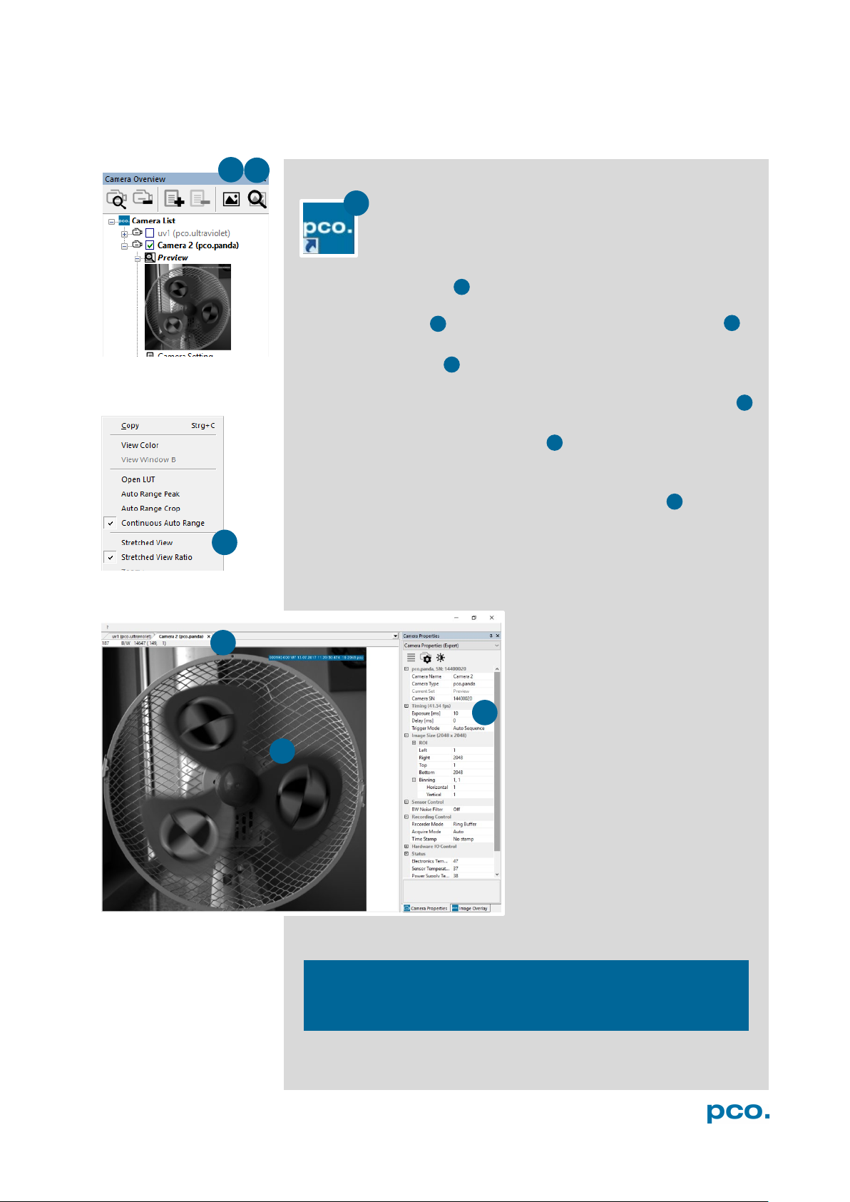
5.3 FIRST IMAGE
Follow the Instructions
•Start pco.camware
•A View Window is shown automatically or open a new one
•Start Live Preview
•Right-click in the view window & apply Continuous Auto Range
•You may adjust Exposure time , aperture and focus of the
mounted lens
•Now you should clearly see the object in the window
To change Exposure time (e.g. the
image is still either too dark or too
bright) or to record and save
images see the pco.camware
manual.
NOTE
Live preview: useful for fast and easy camera adjustment and
focusing.
2
4
5
6
7
3
4
5
1
1
3

11
6
ROLLING
SHUTTER
6. ROLLING SHUTTER
The pco.panda uses the rolling shutter mode. In this mode the pixel
reset and exposure start is carried out line by line. Each line has the
same exposure time, but a different start and end of exposure. Within
one line, the exposure starts simultaneously for all pixels.
The exposure time of each line starts with the corresponding reset of
the line. Then after a predefined time (exposure time), the exposure is
stopped. The light induced accumulated charge carriers of the pixels
in a line are recorded into memory in a low noise (readout) mode. This
way the content of the pixels is assembled in the memory to form the
complete image.
The diagram shows different signal timing settings (see chapter 7.1).
During Show common time of ‘All Lines’ the image sensor is
completely exposed to light. The labels Show time of ‘First Line’
and ‘Last Line’ are the setting for the first / last exposed line and
Show overall time of ‘All Lines’ for the entire exposure period.
There are two different timing cases for rolling shutter mode, which
are explained on the following pages:
•exposure time > sensor readout time
•exposure time < sensor readout time
Rolling Shutter General Timing Diagram
Timing
Camera
Exposure time
Delay time
Line time
pco.panda 4.2
10 µs … 5 s
0 … 5 s
12.136 µs
pco.panda 4.2 bi (UV)
10 µs … 500 ms
0 … 5 s
12.174 µs
NOTE
The
exposure and
delay time can be
adjusted in steps of
one line time.

12
Exposure time > Sensor frame readout time
In case the required exposure time is longer than the frame readout
time, the image sensor is completely exposed to light for some time
(Show common time of ‘All Lines’ also see General Timing
Diagram). In case of a triggered flash illumination, this would be the
best moment to illuminate the image sensor. The hardware signal for
the time Show common time of ‘All Lines’ is available on SMA
connector #4 (see 7.1).
This is an example timing diagram for Trigger Mode Auto
Sequence, SMA explanation see 7.1
Δt = 4.5 µs (pco.panda 4.2)
Δt = 4.4 µs (pco.panda 4.2 bi (UV))

13
6
ROLLING
SHUTTER
Exposure time < Sensor frame readout time
In case the required exposure time is shorter than the frame readout
time, the image is readout through an exposure band moving from
the top to the bottom of the sensor.
For example:
How can you calculate the band of simultaneous exposure lines at an
exposure time of 100µs (@ full resolution)?
Exposure time
Line time = Number of simultaneous exposure lines
100 µs
12.136 µ = 8,2 →8 lines
This is an example timing diagram for Trigger Mode Auto
Sequence, SMA explanation see 7.1
exposure stop & readout
reset & exposure start
band of simultaneous exposures

14
Details for External Exposure Start and External Exposure Control
The detailed timing for external trigger includes system delay times,
an adjustable additional delay time, and the jitter. Explanation for all
Trigger Modes see pco.camware manual.
Name Explanation Value
t
jit
Jitter
≤1 line time
1
t
rsys
Fixed system delay of rising edge
2x line time
1
t
delay
Programmable delay time
0 µs … 5 s
1line time: pco.panda 4.2 / 4.2 bi (UV): 12.136 µs / 12.174 µs
For optimized synchronization (minimized jitter time) use the falling
edge of the line signal at the Status Expos output SMA #4 (see 7.1).
System time trsys is depending on your camera settings and can be
read out from your camera, for further information see SDK manual
function PCO_GetImageTiming.
NOTE
The jitter tjit
can be a
maximum of one line
time.

15
7
CAMWARE
SOFTWARE
1
2
3
4
7. CAMWARE SOFTWARE
This chapter contains only camera-specific additions to the
pco.camware manual. All main functions and explanations can be
found in the pco.camware manual.
7.1 HARDWARE IO CONTROL
Change setting are done via drop-down menu.
Exposure Trigger
If checked, a signal for External Exposure Start Trigger Mode
(see chapter 6.3.1) is accepted at the Exposure Trigger SMA
input #1.
Exposure Trigger: On; Off
Signal Polarity: Rising; Falling
Aquire Enable
If checked, a signal for Acquire Mode is accepted at the Acquire
Enable SMA input #2.
Acquire Enable: On; Off
Signal Polarity: High; Low
Status Busy / Status Line
If checked on, a signal indicating busy status is provided at the
Status Busy output. Once an acceptable trigger edge is received,
‘busy’ goes to status high. As soon as ‘busy’ goes low again, a new
trigger edge is accepted. Use the falling edge of the Status Line
signal for optimized synchronization see Status Expos SMA#4
Status Busy: On; Off
Signal Polarity: High; Low
Status Expos / Status Line
If checked, a signal indicating exposure or line status is given at the
status output. Status Expos indicates the actual exposure window
for one frame. Use the falling edge of the Status Line signal for
optimized synchronization.
Detailed explanation for Signal timing see next page!
Select IO Signal: Status Expos; Status Line
Signal timing:Show time of ‘First Line’; Show common time of ‘All
lines’; Show time of ‘Last line’; Show overall time of ‘All lines’
Status Expos: On; Off
Signal Polarity: High; Low
1
2
3
4
1
2
3
4

16
Enabling and Polarity of IO Signals
The polarity of the input and output signals indicating their active
states is selectable (positive or negative logic).
The polarity of level-sensitive signals can be set to High (positive
logic) or Low (negative logic).
The polarity of edge-sensitive signals can be set to Rising (positive
logic) or Falling (negative logic).
Detailed Explanation for Status Expos SMA #4 Signal Timing
Setting in pco.camware:
There are four different signal types selectable. The example timing
diagram shows all four different possibilities:
•Shows the exposure time of the first line
•Shows when all sensor lines are exposed
•Shows the exposure time of the last line
•Shows if any sensor line is integrating
1
2
4
3
1
2
4
3
1
2
3
4

17
APPENDIX
APPENDIX
A1 TECHNICAL DATA 18
A1.1 DATA SHEET 18
A1.2 MECHANICAL DIMENSIONS 19
A1.3 REAR PANEL 20
A2 HARDWARE MOUNTING 21
A2.1 USB CARD INSTALLATION 21
A2.2 CABLE MOUNTING 22
A2.3 REMOVAL OF THE INPUT WINDOW 23
A3 F-MOUNT ADAPTER (OPTIONAL) 24
A3.1 PCO F-MOUNT ADAPTER 24
A3.2 CHANGE FROM C-MOUNT TO F-MOUNT 25
A4 IMAGE FILE FORMATS 26
A5 CUSTOMER SERVICE 28
A5.1 SERVICE 28
A5.2 MAINTENANCE 28
A5.3 RECYCLING 28
A5.4 TROUBLE SHOOTING 29
A6 INDEX 30
ABOUT PCO 31

18
A1 TECHNICAL DATA
A1.1 DATA SHEET
Image sensor
pco.panda 4.2
pco.panda 4.2 bi (UV)
Type of sensor
customized sCMOS
back illuminated
sCMOS
Color
monochrome / color
monochrome
Resolution (h x v)
2048 x 2048 pixel
Pixel size (h x v)
6.5 µm x 6.5 µm
Sensor format /
diagonal
13.3 x 13.3 mm / 18 mm
Shutter mode
Rolling Shutter
Camera
Frame rate
40 fps @ full resolution
Exposure / shutter
time
10 µs ... 5 s
10 µs … 500 ms
Dynamic range A/D
16 bit
Pixel scan rate
44 MHz
46 MHz
Pixel data rate
176.0 Mpixel/s
184 Mpixel/s
Binning (h x v)
1x1 ... 4x4
Cooling method
passive cooled
Trigger input signals
frame trigger, acquire (SMA connectors)
Trigger output signals
exposure, busy (SMA connectors)
Data interface
USB 3.1 Gen1
Timestamp
in image (1 µs resolution)
General
Power delivery
via USB Type-C
Power consumption
typ. 4.5 W (max. 6.0 W)
Weight
420 g
Operating temperature
+10°C ... +40°C
Operating humidity range
10% ... 80% (non-condensing)
Storing temperature range
-10°C ... +60°C
Optical interface
C-mount, F-mount (optional)
CE / FCC certified
yes
ROI (region of interest) step sizes
Horizontal steps
32 pixel steps
Vertical steps
8 pixel steps
Minimum ROI
64 x 16 pixel
Subject to change, refer to current data sheet available on our website.

19
A1 TECHNICAL DATA
A1.2 MECHANICAL DIMENSIONS
All dimensions given in millimeter.
2D and 3D technical drawings are available on our website
3D step files and further technical drawings are available on request.
NOTE
C-Mount flange focal
distance: 17.52 mm

20
A1.3 REAR PANEL
Status LEDs
(LED1: green / red; LED 2: orange)
Color
Description
Red / green continuous
Camera is booting
Green
Camera is ready for operation
Orange continuous
Arm camera / rec state off
Orange blinking
Recording on
Red continuous
Error
Interface Connector
USB 3.1 plug Type-C screwable;
Power delivery for the camera over USB cable
SMA Inputs
(see chapter 7.1)
Input (1=Exposure Trigger; 2=Acquire Enable)
Type
Digital
Level
3.3 V LVTTL (5 V tolerant)
Coupling
DC
Impedance
1 kΩ
Slew rate
> 1 V/ms
SMA Outputs
(see chapter 7.1)
Output (3=Status Busy; 4=Status Expos)
Type
Digital
Level
3.3 V LVTTL
Coupling
DC
3
1
4
2
1
4
3
2
Other manuals for pco.panda 4.2
2
This manual suits for next models
2
Table of contents
Other Pco Digital Camera manuals


Popular Digital Camera manuals by other brands

Global Point Products
Global Point Products Pixie Princess user manual

Samsung
Samsung S850 - Digital Camera - Compact Manual de usuario

Nikon
Nikon COOLPIX S5200 Reference manual

Canon
Canon PowerShot S100 DIGITAL ELPH user manual

Argus
Argus DC-6340 Specification sheet

Insignia
Insignia NS-DSC1112SL Guía del usuario


