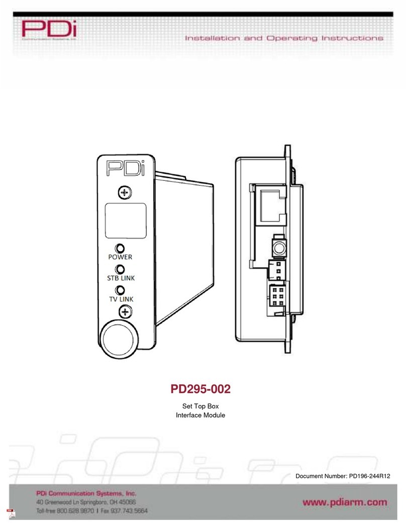
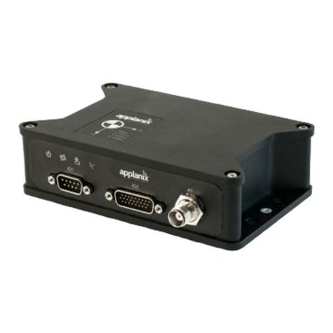
PDi PD251-047 User manual

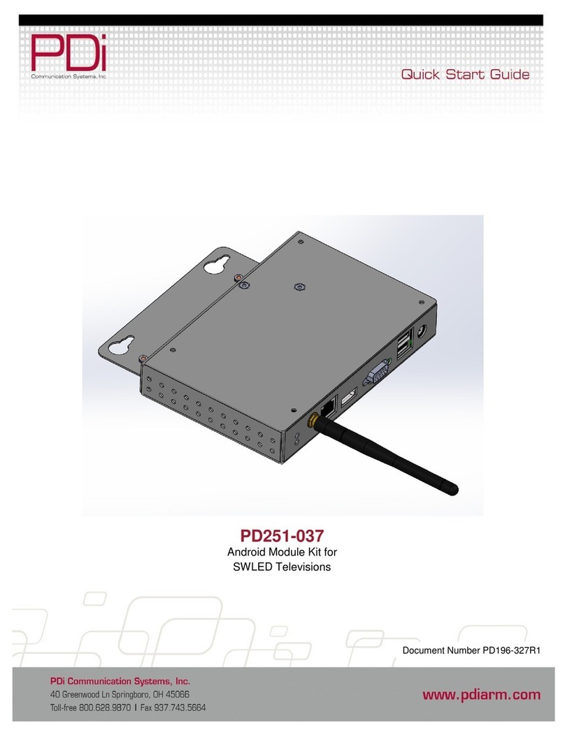
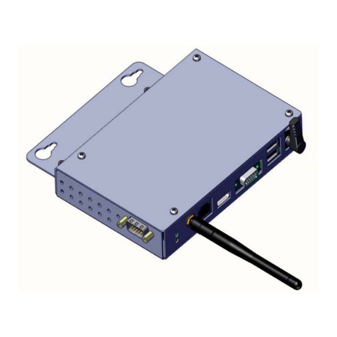
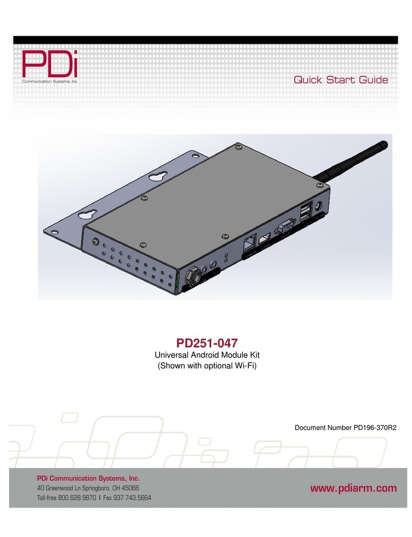
PD251-047
Universal Android Module Kit
(Shown with optional Wi-Fi)
Document Number PD196-370R1

PD196-370R1 PD251-047 Universal Android Module Kit Page 2 of 10
PDi Communication Systems, Inc. 40 Greenwood Lane Springboro, Ohio 45066 USA PH 1-800-628-9870 FX 937-743-5664
Copyright, Trademarks, and Disclaimer
Copyright,Trademarks
© 2016 PDi Communication Systems, Inc. All rights reserved. PDi-TAB® is a registered trademark of PDi Communication
Systems, Inc. Product logos, brands and other trademarks displayed within PDi’s products are the property of their
respective trademark holders, who are not affiliated with, endorsing, or sponsoring PDi Communication Systems, Inc. or
our products.
Disclaimer
The author and publisher have used their best efforts in preparing this manual. PDi Communication Systems, Inc. makes
no representation or warranties with respect to the accuracy or completeness of the contents of this manual and
specifically disclaims any implied warranties or merchantability or fitness for any particular purpose and shall in no event
be liable for any loss of profit or any other damages. The information contained herein is believed accurate, but is not
warranted, and is subject to change without notice or obligation.
SAFETY INSTRUCTIONS
CAUTION: THIS INSTALLATION SHOULD BE MADE BY A QUALIFIED SERVICE PERSON AND SHOULD
CONFORM TO ALL LOCAL CODES. READ AND FOLLOW THE SAFETY INSTRUCTIONS BEFORE ATTEMPTING
THIS INSTALLATION.
1. Read Instructions – All the safety and operating
instructions should be read before the product is
operated.
2. Keep these Instructions – The safety and
operating instructions should be retained for
future reference.
3. Heed all Warnings – All warnings on the product
and in the operating instructions should be
adhered to.
4. Follow all Instructions – All warnings on the
product and in the operating instructions should
be followed.
5. Water and Moisture – Do not expose this
product to rain or moisture. Do not use this
product near water – for example, near a bath
tub, wash bowl, kitchen sink, or laundry tub; in a
wet basement; or near a swimming pool; and the
like.
6. Cleaning – Unplug this product from the wall
outlet before cleaning. Do not use liquid
cleaners or aerosol cleaners. Clean only with a
dry cloth.
7. Ventilation – Slots and openings in the cabinet
are provided for ventilation to ensure reliable
operation of the product and to protect it from
overheating. These openings must not be
blocked or covered. The openings should never
be blocked by placing the product on a bed,
sofa, rug, or other similar surface. This product
should not be placed in a built-in installation
such as a bookcase or rack unless proper
ventilation is provided or the manufacturer’s
instructions have been adhered to.
8. Heat – The product should be situated away
from heat sources such as radiators, heat
registers, stoves, or other products (including
amplifiers) that produce heat.
9. Power-Cord Protection – Protect the power cord
from being walked on or pinched, particularly at
plugs, convenience receptacles, and the point
where they exit from the product.
10. Attachments – Only use
attachments/accessories specified by the
manufacturer.
11. Servicing –Refer all servicing to qualified service
personnel. Servicing is required when the
apparatus has been damaged in any way, such
as power cord or plug is damaged, liquid has
been spilled or objects have fallen into the
apparatus, the apparatus has been exposed to
rain or moisture, does not operate normally, or
has been dropped.
12. Oxygen Environment – Do not use in an oxygen
tent or oxygen chamber. Such use may cause a
fire hazard.
13. Power Sources – This product should be
operated only from the type of power source
indicated on the marking label. If you are not
sure of the type of power supply to your home,
consult your product dealer or local power
company. For products intended to operate
from battery power, or other sources, refer to the
operating instructions.
14. To ensure proper operation and to meet safety
and electromagnetic interference (EMI)
requirements, you must connect the module to
earth ground before you connect power. You
must use the protective earthing terminal on the
chassis to connect the module to earth ground.
A qualified electrician must install the ground
wire to the module and to a proper earth ground.

PD196-370R1 PD251-047 Universal Android Module Kit Page 3 of 10
PDi Communication Systems, Inc. 40 Greenwood Lane Springboro, Ohio 45066 USA PH 1-800-628-9870 FX 937-743-5664
.
Technical Specifications*
CORE FEATURES
OS
Android 4.3 (Jelly Bean)
CPU
Arm A9 Quad Core 1.0GHz
GPU 2D & 3D accelerator
Ethernet
100/1000 Mbps
RAM 1GB
Storage 8GB total. 3GB available for patient apps
including up to 1GB for media files
USB Web Camera Compatible
YES
WIFI (OPTIONAL)
WiFi Compatibility 802.11b/g/n/ac
WiFi Radio
Intel Dual Band Wireless-AC 3160
POWER
Power
Consumption Max 13W
Voltage
12V DC
Connections
Optional Wifi
Antenna
Ethernet
HDMI
Service Port
USB
Power
Cable
IR
TV
Audio In
Pillow
Speaker
Power
LED
*Technical specifications could change without prior notice

PD196-370R1 PD251-047 Universal Android Module Kit Page 4 of 10
PDi Communication Systems, Inc. 40 Greenwood Lane Springboro, Ohio 45066 USA PH 1-800-628-9870 FX 937-743-5664
Installation
PDi offers a wide range of wall, floor and ceiling mounting options. Installation of the Universal Android Module
is shown with compatible PDi brackets. Use of any other bracket may require modification of installation. The
Universal Android Module contains a 100mm and 200mm VESA pattern. Contact PDi for compatible PDi
bracket information.
Tool List:
1. Safety glasses/goggles
2. P1 or P2 Phillips screwdriver
Safety Steps:
1. Always wear safety glasses/goggles to prevent injury from debris.
2. Follow the installation/removal instructions for your existing products.
Parts List
PART NUMBER
QTY
DESCRIPTION
PD251-047
1
UNIVERSAL ANDROID MODULE
PD106-888
1
HDMI MALE TO MALE 36” CABLE
PD106-886
1
IR XMIT/RCV CABLE
PD196-370
1
QUICK START GUIDE, UNIVERSAL ANDROID MODULE
PDIPPHMSM4X710
2
M4 PHILLIPS SCREW
PDIPPHMSM6X110
2
M6 PHILLIPS SCREW
Mounting
The Universal Android Module is designed to mount to the rear of most televisions with standard 100mm or
200mm VESA mount points. These instructions assume the PDi PD168-033 mounting kit or PD168-103
mounting kit (Purchased Separately) are being used.
Step 1 (200mm Mounting Holes):
Loosen (2) M6 screws on the PD168-033 kit plate and insert Universal Android Module between plate and TV.
Tighten (2) M6 screws.
Step 1 (100mm Mounting Holes):
Loosen (2) M4 screws on the PD168-103 kit plate and place Universal Android Module on top of mounting
plate. Tighten (2) M4 screws.
Step 2:
Remount the television per manufacturer’s installation instructions for your product.
Mounting using 200mm holes
Mounting using 100mm holes

PD196-370R1 PD251-047 Universal Android Module Kit Page 5 of 10
PDi Communication Systems, Inc. 40 Greenwood Lane Springboro, Ohio 45066 USA PH 1-800-628-9870 FX 937-743-5664
Ground Connection
1. Obtain 14AWG stranded copper wire with 90°C green/yellow-stripe insulation, or as required by local electrical
code.
2. Terminate the wire at one end with Panduit P14-4R or equivalent listed terminal for a #4 screw.
3. Terminate the other end of the wire as appropriate for your installation.
4. Connect one end of the grounding cable to a permanent earth ground, such as the AC outlet wall plate.
5. Place the ring terminal attached to the grounding cable over the supplied #4 screw.
6. Secure the grounding screw to the protective earthing location on the module.
IR Cable Connection
1. Attach the supplied Infrared (IR) transmitter/receiver cable to the Universal Android Module’s “IR” connector.
2. The small end of the cable is the IR transmitter. It must be affixed to the TV on top of the TV’s IR window so that
the TV can see the signals sent from this transmitter.
3. It is recommended to use black electrical tape to cover the IR transmitter so no other signals will pass into the TV.
4. The device in the middle of the cable is the IR receiver. Mount it on the side of the TV or a nearby surface so that
it can see the IR beam from the TV’s remote control. If the TV’s remote will not be used in this application, then
skip this step. Note the Universal Module is not compatible with all TV’s remote codes. Please contact PDI
Communication Systems for compatibility information.

PD196-370R1 PD251-047 Universal Android Module Kit Page 6 of 10
PDi Communication Systems, Inc. 40 Greenwood Lane Springboro, Ohio 45066 USA PH 1-800-628-9870 FX 937-743-5664
Pillow Speaker Connection
The Universal Android Module is compatible with most pillow speakers available today. The pillow speaker may connect
directly to the module, or it may route through a nurse call system. In either case, the data, speaker, and common signals
must terminate into a ¼” phone plug. Verify the proper termination then attach the phone plug to the module as shown.
If needed, the following jumper cables may be ordered from PDI Communication Systems.
ACROSS ROOM WIRING
JUMPER

PD196-370R1 PD251-047 Universal Android Module Kit Page 7 of 10
PDi Communication Systems, Inc. 40 Greenwood Lane Springboro, Ohio 45066 USA PH 1-800-628-9870 FX 937-743-5664
TV Audio Connection
If it is necessary to route TV audio through the pillow speaker, then connect an appropriate audio patch cable (purchased
separately) between the Universal Android Module’s “TV AUDIO IN” connector and the TV’s audio output.
Power Adapter and HDMI Connections
Attach the supplied HDMI cable to the Universal Android Module. Attach the other end to any free HDMI port on the TV.
Finally attach the PD239-237 power adapter to the Universal Android Module, then to AC power.

PD196-370R1 PD251-047 Universal Android Module Kit Page 8 of 10
PDi Communication Systems, Inc. 40 Greenwood Lane Springboro, Ohio 45066 USA PH 1-800-628-9870 FX 937-743-5664
Screen Format Configuration
Set the TV to display the Universal Android Module by choosing the corresponding HDMI input. The default screen
format may be zoomed so that the edges are cropped. Repeatedly press the ARC or ASPECT button on the remote
supplied with the TV until the on-screen display shows “Full Screen” or “Just Scan”.
Keyboard
You may have the PD161-004 PDi wireless keyboard (purchased separately) or other compatible keyboard for use with
this module. If you are using the PDi wireless keyboard, it will function as any 83 key QWERTY keyboard with several
“Hot” keys.
Hot Keys
Function
Fn/Pair
Pair Keyboard with Module
Esc
Back one screen
Fn/Home
Home screen
Pull Down Panels
By pressing the mouse and scrolling down from the top, you can reveal two different information panels.
Quick settings panel. This is on the right side of a screen and
gives you direct entry into different areas of the settings app,
depending on which icon you choose.
Notification panel. This is on the left side of a screen
and provides you with system notifications. Selecting
one of these notifications can take you directly to the
app responsible for it.

PD196-370R1 PD251-047 Universal Android Module Kit Page 9 of 10
PDi Communication Systems, Inc. 40 Greenwood Lane Springboro, Ohio 45066 USA PH 1-800-628-9870 FX 937-743-5664
Settings
From the android home screen select “ALL APPS”, then select “Settings”. You will enter the Setting screen where you
can adjust network, sound, and account settings.
Connect To Wi-Fi Networks (Optional)
If the Universal Android Module has the Wi-Fi option, follow the
instructions to connect to a wi-fi network.
1. Open Settings.
2. Slide the Wi-Fi switch to the On position.
(If not already set to “on”)
3. The module scans for available Wi-Fi networks and
displays the names of those it finds. Secured networks are indicated with a locked icon.
4. If the module finds a network that you connected to previously, it connects to it.
5. Select a network name to see more details or connect to
it, and type a security code if necessary.
Troubleshooting
Hard Reset Information
If the TV becomes unresponsive, remove power from the Universal Android Module and reconnect power.
Additional Information
Additional information is available in the user manual. You can access this information online at http://pdidisplays.com.
For instructional installation video go to http://youtube.com/pdiuniversity.

PD196-370R1 PD251-047 Universal Android Module Kit Page 10 of 10
PDi Communication Systems, Inc. 40 Greenwood Lane Springboro, Ohio 45066 USA PH 1-800-628-9870 FX 937-743-5664
Limited Warranty
PDi Communication Systems Inc., (“PDi”) warrants, to the original purchaser only, that the product will be free from
defects in materials and workmanship, under normal use, for 2 years from the date of original purchase. This warranty
does not cover any other equipment that may have been included with PDi’s shipment of this product.
After receipt of written notice of a defect or malfunction occurring during the warranty period, PDi will repair or replace
goods returned to its Springboro, Ohio location, at its discretion, the whole or any component part of any product
manufactured by PDi and found by PDi to be defective. If the decision is made to replace the product, PDi will exchange
the model for the same model or a model similar in form and function.
As a condition to obtaining warranty service, written notification of the defective product must be received by PDi within
ten (10) days of noticing the defect. Repair of said product requires it to be shipped to the PDi factory in Springboro,
Ohio. All shipments shall be F.O.B. Springboro, Ohio, and all shipping and freight charges to PDi’s factory shall be paid
by the customer.
For information regarding authorized servicing and all other information pertaining to this warranty, please contact PDi
COMMUNICATION SYSTEMS at 40 Greenwood Lane, Springboro, Ohio 45066 or phone 800-628-9870 and ask for
Service.
This warranty gives specific legal rights and you may also have other rights which vary from state to state.
Exclusions from Warranty
•Products damaged by any catastrophe, accident, or from neglect, misuse, fault, improper assembly, improper
maintenance, inadequate return packaging, or negligence by the customer or any third party. They will be treated
as out of warranty for external cause to the Products, such as, but not limited to, failure of or faulty electric power,
air conditioning, operator error, failure or malfunction of any data communications system. Such conditions will be
determined by PDi at its sole unfettered discretion.
•Service and repair of accessories, apparatus, attachments or any other devices which are not PDi products or
options.
•Defacing of product, revision control and PDi labeling (label alterations, serial number missing, serial number no
longer discernible and serial number invalid). All serial numbers are recorded and tracked for warranty purposes.
•Unauthorized changes, modifications or alterations in or to the Products not installed by PDi.
•Damage to or loss of any programs, data, or removable storage media.
•Damage incurred during installation, relocation or removal of the Products or any accessories, apparatus,
attachments or other devices.
•Normal wear.
•The furnishing of accessories or supplies.
•Damage by shipping carrier.
•Incompatibility issues.
•Damages of any kind including, but not limited to, direct or indirect damages, lost profits, lost saving, or other
special incidental, exemplary or consequential damages whether for breach of contract, tort or otherwise, or
whether arising out of the use of or inability to use the product, even if PDi or any distributor, dealer, or authorized
service provider has been advised of the possibility of such damages, or any claim by any other party
•Damage caused by any software or application not installed at the factory.
PDi’s liability under this warranty is limited to repair or replacement of defective products and parts as provided above.
PDi shall not be liable for incidental or consequential damages.*
The warranty contained herein is in lieu of all other expressed or implied warranties, including any implied warranty of
merchantability or fitness for any particular purpose. PDi neither assumes nor authorizes any person to assume, on its
behalf, any other obligation or liability.
*Some states do not allow the exclusion of limitation of incidental or consequential damages or a disclaimer of warranties
implied by law, so the above limitation or exclusion may not apply.
The information and technical data in this manual is believed accurate, but is not warranted and is subject to change
without notice or obligation. PDi reserves the right to change this policy without advance notice.
Other manuals for PD251-047
1
Table of contents
Other PDi Control Unit manuals
Popular Control Unit manuals by other brands
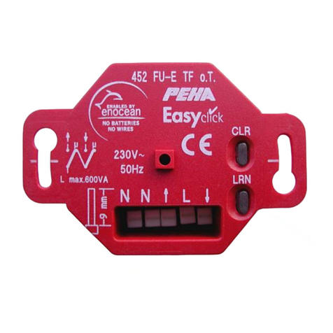
PEHA
PEHA 452 FU-E TF o.T Installation and operating instructions
Leviton
Leviton 71I00-1 Installation instructions and user guide

Cabletron Systems
Cabletron Systems SPECTRUM FDM manual
Discovery Telecom
Discovery Telecom EPGM1 user manual
Sony
Sony HXCU-FB80 Service manual

Dickey-John
Dickey-John Land Manager SE manual
