PDi 1000 Series User manual
MODEL NUMBER:
1000 Series CMT Arm
Document Number:
PD196-326R3
Installation Instruction for 1000 Series CMT Arm
with 48” Vertical Travel
Page 1 of 5
PDi Communication Systems, Inc. 40 Greenwood Lane Springboro, Ohio 45066 USA PH 1-800-628-9870 FX 937-743-5664
THIS INSTALLATION SHOULD BE MADE BY A QUALIFIED SERVICE PERSON AND SHOULD CONFORM TO ALL
LOCAL CODES. READ AND FOLLOW THE SAFETY INSTRUCTIONS BEFORE ATTEMPTING THIS INSTALLATION.
NOTE to CATV system installer: This reminder is provided to call the CATV system installer's attention to Article 820-40
of the NEC that provides guidelines for proper grounding and, in particular, specifies that the cable ground shall be
connected to the grounding system of the building, as close to the point of cable entry as practical.
WARNING: OXYGEN ENVIRONMENT DO
NOT use in an oxygen tent or oxygen
chamber. Such use may cause a fire hazard.
WARNING: To avoid the hazards of fire or
electric shock, DO NOT expose this TV to rain
or moisture.
DANGER: ARM RECOIL HAZARD The
safety brake pin must remain in the
SAFETY BRAKE PIN HOLE whenever the
television set is removed from the arm or
when the arm is removed from the wall
bracket to prevent the arm from springing
open.
Apparatus shall not be exposed to dripping or splashing and no objects filled with liquids, such as vases, shall be placed
on the apparatus. Unplug this unit from the wall outlet before cleaning. Do not use liquid cleaners or aerosol cleaners. Use
a damp cloth for cleaning. This unit REQUIRES periodic maintenance. Refer to the maintenance section for instructions.
1. Read these instructions.
2. Keep these instructions.
3. Heed all warnings.
4. Follow all instructions.
5. Do not use this apparatus near water.
6. Clean only with dry cloth.
7. Do no block any ventilation openings. Install in
accordance with the manufacturer's instructions.
8. Do not install near any heat source such as radiators,
heat registers, stove, or other apparatus (including
amplifiers) that produce heat.
9. Use only with the cart, stand, tripod, bracket or table
specified by the manufacturer, or sold
with the apparatus. When a cart is used,
use caution when moving the
cart/apparatus combination to avoid
injury from tip-over.
10. Do not defeat the safety purpose of the polarized or
grounding-type plug. A polarized plug has two blades
with one wider than the other. A grounding type plug has
two blades and a third grounding prong. The wide blade
or the third prongs are provided for your safety. If the
provided plug does not fit into your outlet, consult an
electrician for replacement of the obsolete outlet.
11. Protect the power cord from being walked on or
pinched particularly at plugs, convenience receptacles,
and the point where they exit from the apparatus.
12. Only use attachments/accessories specified by the
manufacturer.
13. Unplug this apparatus during lightning storms or
when unused for long periods of time.
14. Refer all servicing to qualified service personnel.
Servicing is required when the apparatus has been
damaged in any way, such as power-supply cord or plug
is damaged, liquid has been spilled or objects have
fallen into the apparatus, the apparatus has been
exposed to rain or moisture, does not operate normally,
or has been dropped.
Contact PDi for complete list of approved TV model numbers for which this arm can be used.

MODEL NUMBER:
1000 Series CMT Arm
Document Number:
PD196-326R3
Installation Instruction for 1000 Series CMT Arm
with 48” Vertical Travel
Page 2 of 5
PDi Communication Systems, Inc. 40 Greenwood Lane Springboro, Ohio 45066 USA PH 1-800-628-9870 FX 937-743-5664
Scope:
How to install a PDI-CMT-SUPPORT.
How to install a 1000 series PDi Super Reach Ceiling Mount ARM to a PDI-CMT support.
Tool List:
1) Safety glasses/goggles
2) P1 OR P2 Phillips screw driver
3) 5/32 Hex key or hex bit and driver
4) 3/16 Hex key or hex bit and driver
5) SUITABLE tools needed for mounting the PDI-CMT-SUPPORT to the building structure.
6) (2) 9/16" wrenches
7) Drill with a 3/8" drill bit
Safety steps:
1) Always wear safety glasses/goggles to prevent injury from debris.
2) Follow the installation/removal instructions for your existing products.
Procedure Overview:
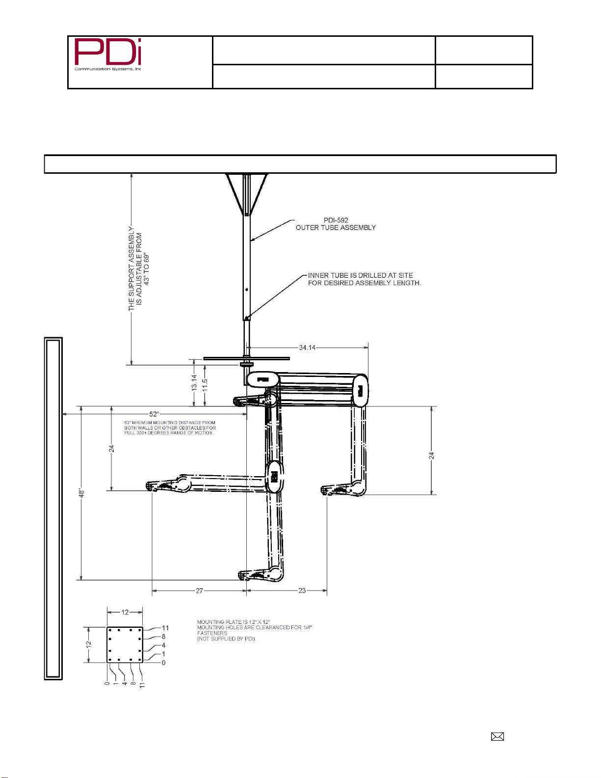
A complete mounting system for attachment to a solid roofing structure above a suspended tile ceiling. Outer tube mounts
to a solid surface, inner tube allows adjustment of height to clear the tile ceiling, and then a special arm section attaches
to the bottom of the tube. These various CEILING MOUNT ARM models can support up to 13 pounds.
PDI-592
OUTER TUBE
CEILING TILE
(NOT INCLUDED
IN PDI PRODUCT
PDI CEILING MOUNT ARM SPECIFIC MODEL
NUMBER IS DEPENDANT ON APPLICATION OPTION
OPTIONAL VESA PENDANT
ON SPECIAL MODELS ONLY
MODEL NUMBER:
1000 Series CMT Arm
Document Number:
PD196-326R3
Installation Instruction for 1000 Series CMT Arm
with 48” Vertical Travel
Page 3 of 5
PDi Communication Systems, Inc. 40 Greenwood Lane Springboro, Ohio 45066 USA PH 1-800-628-9870 FX 937-743-5664
LOCATE AND MOUNT OUTER TUBE
1. Remove the ceiling tile and locate a mounting position above the patient's bed at a minimum distance of 52 inches from
walls or other obstacles.
2. Mount the outer tube PDI-592 securely to the ceiling using the twelve mounting holes provided in the plate.

MODEL NUMBER:
1000 Series CMT Arm
Document Number:
PD196-326R3
Installation Instruction for 1000 Series CMT Arm
with 48” Vertical Travel
Page 4 of 5
PDi Communication Systems, Inc. 40 Greenwood Lane Springboro, Ohio 45066 USA PH 1-800-628-9870 FX 937-743-5664
Adjust Height and Drill Inner Tube
1. Slide the inner tube PDI-591 up to the desired height. Insert the plastic sleeve PDI-590 until the shoulder is seated in
the outer tube and rotate until the predrilled holes on both the outer tube PDI-592 and the plastic sleeve PDI-590 are
aligned. Drill through the inner tube from each side using the predrilled holes as a locater. Use a 3/8” diameter drill bit.
Slide the 3/8” x 2-1/2” bolt through and tighten nut. Cut hole for tube in ceiling tile and replace tile.
2. Drop a fish wire through the cable exit hole located near the base plate of the outer tube (not shown). The wire should
exit the bottom of the tube. Remove the four ¼-20 socket head bolts from the swivel collar PDI-589. Attach the fish wire to
the cable pigtail(s) that exit the arm swivel cap elbow. Being sure to first thread the cable(s) through both the top and
bottom plastic shim washers PDI-586.
Attach the Arm Section
3. Pull the fish wire through the tube until the cables exit the base plate hole. Hold the plastic shim washer PDI-586
against the bottom of the inner tube PDI-591. Be sure it does not overlap the swivel collar. Hold the arm assembly against
the bottom of the inner tube. The supplied thread locking compound LOCTITE® #242 (Blue) must be used on the ¼-20
socket head bolts. Slide the ¼-20 socket head bolts through the swivel cap PDI-688 and thread back into the swivel collar
PDI-589. Tighten the ¼-20 socket head bolts to a torque of 10 ft-lbs.

MODEL NUMBER:
1000 Series CMT Arm
Document Number:
PD196-326R3
Installation Instruction for 1000 Series CMT Arm
with 48” Vertical Travel
Page 5 of 5
PDi Communication Systems, Inc. 40 Greenwood Lane Springboro, Ohio 45066 USA PH 1-800-628-9870 FX 937-743-5664
ARM MAINTENANCE
Very little maintenance should be required for your PDI Arm to give years of trouble free service if the following lubrication
and inspection procedures are followed.
1. INSPECTION - Occasionally check the elbow swivel joint for any evidence of bending or distortion due to a patient
using the ARM for assistance in getting in or out of bed or any other misuse. If the ARM is not mounted with thesupport
tube assembly absolutely vertical, it will have a tendency to drift and will not properly counter balance the television. Be
certain that the support tube assembly that the arm is mounted to is vertical.
2. SPRING ADJUSTMENT - The gas spring in this arm support a specific weight range for the model construction. These
springs are not "adjustable. The pivot points for some arm models can be moved to alter the weight capacity. Please
contact the manufacturer for details. Otherwise the gas springs will have to be changed to alter the weight capacity of the
arm.
3. LUBRICATION - At least once a year a drop of light machine oil should be put on each pivot point in the nose, elbow,
and base. DO NOT PUT OIL ON THE FRICTION DAMPER PADS!
4. REPLACEMENT OF COAX CABLE - See cable replacement procedure in the full maintenance manual for your arm.
5. TORQUE ADJUSTMENT OF PIVOT SCREWS - All screws in the ARM are tightened securely, and Loctite, at the
factory and do not require specific checks with a torque wrench. IF THE THREADS ARE STRIPPED IN THE NOSE,
ELBOW, OR BASE, THAT PART NEEDS REPLACEMENT - DISCONTINUE USE IMMEDIATELY.
OIL INTERIOR
PIVOTS
ELBOW SWIVEL JOINT
OIL INTERIOR
PIVOT
NO OIL
OIL INTERIOR
PIVOTS
Optional VESA pendant
NO OIL
Table of contents
Other PDi Medical Equipment manuals


Popular Medical Equipment manuals by other brands


ReBuilder Medical
ReBuilder Medical 2407 manual

Olympus
Olympus UHI-2 Maintenance manual

Synthes
Synthes LCP Distal Humerus Plates Technique guide

OmniPod
OmniPod PDM CAT45E Caregiver guide

Darco
Darco Body Armor Walker Instructions for use

Fehling Instruments
Fehling Instruments CERAMO APART PUNCHES Assembly instructions


