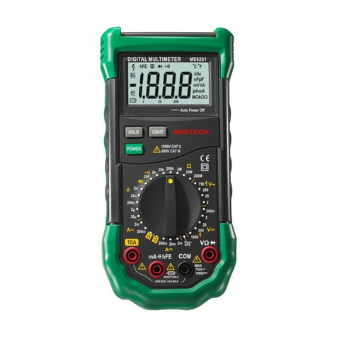
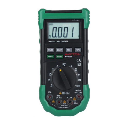
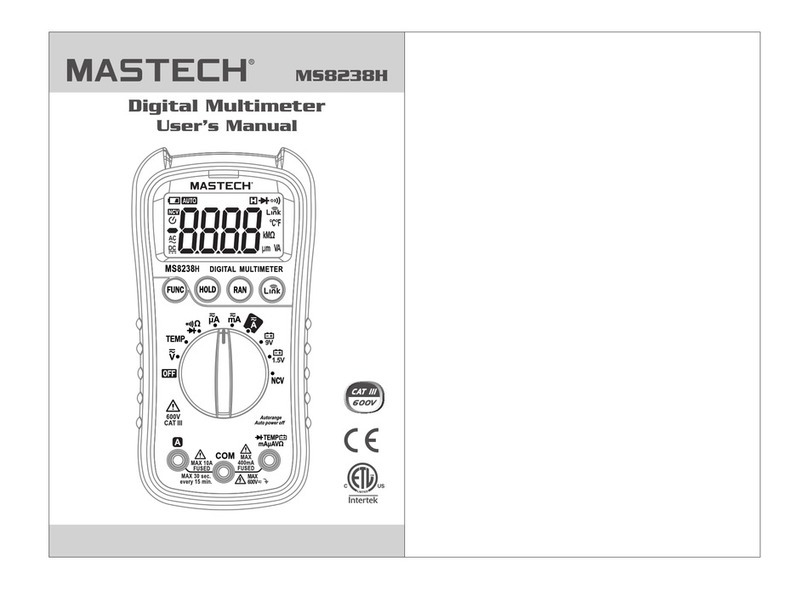
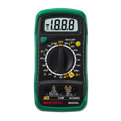
Mastech MY67 User manual

CONTENTS
1. SAFETY INFORMATION .1
2. DESCRIPTION .. 3
3. OPERATINGINSTRUCTION ..6
3.1MEASURINGVOLTAGE .6
3.2MEASURINGCURRENT 6
3.3MEASURINGRESISTANCE ..7
3.4MEASURINGFREQUENCY 7
3.5MEASURINGCAPACITANCE 8
3.6CONTINUITY TEST .. ...8
3.7DOIDE TEST ..8
3.9TRANSISTORTEST .9
4. SPECIFICATIONS .9
5. ACCESSORIES 13
6. BATTERY & FUSE REPLACEMENT 14

1. SAFETYINFORMATION
Thismultimeterhasbeen designed according to
IEC-1010 concerning electronicmeasuringinstruments
withanovervoltagecategory(CAT )and pollution 2.
Followall safetyand operatinginstructionstoensure
thatthemeterisused safelyand iskeptingood
operating condition.
1.1PRELIMINARY
※Whenusingthismeter,theusermustobserveall
normalsafetyrulesconcerning:
—Protection against thedangersofelectricalcurrent.
—Protection ofthemeteragainst misuse.
※Full compliancewithsafetystandardscanbe
guaranteed onlyifused withtestleadssupplied.If
necessary,theymustbereplaced withthesamemodelor
sameelectronicratings.Measuring leadsmustbein
good condition.
1.2DURINGUSE
※Neverexceed theprotectionlimitvaluesindicatedin
specificationsforeachrangeofmeasurement.
※Whenthemeterislinked tomeasurementcircuit, do
not touchunused terminals.
※Whenthevaluescaletobemeasured isunknown
beforehand,settherangeselectoratthehighest
position.
※Beforerotatingtherangeselectortochange
functions,disconnecttestleadsfromthecircuitunder
-1-

test.
※Whencarryingoutmeasurementson TVor
switching powercircuits,alwaysrememberthatthere
maybehighamplitudevoltagespulsesattestpoints
whichcandamagethemeter.
※Neverperformresistancemeasurementsonlive
circuits.
※Alwaysbecarefulwhenworkingwithvoltages
above60Vdcor30Vacrms.Keepfingersbehind the
probebarrierswhilemeasuring.
1.3SYMBOLS
Importantsafetyinformation,refertotheoperating
manual.
Dangerousvoltagemaybepresent.
Earthground
Doubleinsulation (Protectionclass )
1.4MAINTENANCE
Beforeopening themeter,alwaysdisconnecttest
leadsfromall sourcesofelectriccurrent.
Forcontinueprotectionagainstfire,replacefuse
onlywiththespecifiedvoltageand currentratings:F1:
2A/250VF2: 10A/250V
Ifanyfaultsorabnormalitiesareobserved,the
metercannotbeused anymoreandithastobe
-2-

checkedout.
Neverusethemeterunlesstheback coverisin
placeandfastened fully.
Toclean themeter,useadampclothand mild
detergentonly, donot useabrasivesorsolventson it.
2. DESCRIPTION
Thismeterisanautorangingprofessionalinstrument
with33/4digitLCD display,capableofperforming
functions:
-DC voltagemeasurement
-ACvoltagemeasurement
-DC current measurement
-ACcurrent measurement
-Resistancemeasurement
-Capacitancemeasurement
-Frequencymeasurement
-Diodetest
-Transistortest
-Audiblecontinuitytest
Names ofcomponents
1-4. buttons
5. Rotaryswitch
6. A input jack
7. mAinput jack
8. V/Ω/Hzinput jack
9. COMinput jack
10. Transistorinput jack
-3-

2.1SELECT(Functionselectionbutton)
Thisbuttonisused toselectACAorDCAmeasuring
mode.
2.2RANGE (Auto/manualrangeselectionbutton)
-4-

Thiskeyistheauto/manualkey.Poweron defaultis
automeasurement, andpress onetimetoswitchtothe
manualmeasurement. Inmanualmeasurementmode,
the systemwill jumpup onemodeforeachpress until
thehighestmode,thenreturntothelowestmodeasa
loop.Ifpressthekeyover2seconds,thesystemwill
switchbacktoautomeasurementstatus.Frequency
and capacitancemeasurementcannotusemanual
measurement. Foxexample,atvoltagerangethe
changesareasthefigure.
2.3REL(Relativevaluemeasurement)
Thebutton isforrelativevaluemeasurementexceptHz,
diodeand continuity.
Pushthebuttontogetrelativemeasurementmode,
“REL”annunciatedisplayonLCD.Butstorethe
displayed reading asareferencevalue. IntheRelative
mode,thevalueshownon theLCDisalways the
differencebetweenthestored referencevalueandthe
presentreading.Ifthenewreading isthesameasthe
referencevalue, thedisplaywill bezero.
2.4DATAHOLD
Whenthisbuttonispushed,thedisplaywill keep the
lastreading and “ ” symbolwill appearon theLCD.
Pushing it againreturnsthemetertonormalmode.
-5-

2.5INPUTJACKS
Theunithasfourinputjacksthatareprotectagainst
overload tothelimits.During use,connecttheblacktest
lead totheCOMjackandthered testlead asshown
below:
Function
Redlead
connection
Input limits
V V/Ω/Hz 1000V dcor750V rmsac
ΩV/Ω/Hz 250V dcorrmsac
V/Ω/Hz 250V dcorrmsac
μA/mA mA 500mA dcorrmsac
A A 10A dcorrmsac
μA/mA and A rangesareprotected byfuses.
3.OPERATING INSTRUCTION
3.1MEASURINGVOLTAGE
1. Connect theblacktest lead totheCOMjackandthe
redtest lead totheV/Ωjack.
2.Settherotaryswitchatthedesired V orV ~
rangepositionand connecttestleadsacrossthe
sourceorload undermeasurement.
3.Read LCD display.Thepolarityof thered connection
will beindicated whenmaking adcvoltage
measurement.
3.2MEASURINGCURRENT
1.ConnecttheblacktestleadtotheCOMjackandthe
read test lead tothemA jackforamaximumof500mA.
-6-

Foramaximumof10A, movethered lead totheA jack.
2.Setthefunctionswitchat μA, mAorArangetobe
used and push “SELECT”button toselectDCAorACA
measuring mode.
3.Connecttestleadsinserieswiththeload under
measurement.
4.Read LCDdisplay.Thepolarityofthered lead
connectionwill beindicatedwhenmaking aDC
measurement.
3.3MEASURINGRESISTANCE
1. Connect theblacktest lead totheCOMjackandthe
redtest lead totheV/Ω/Hzjack. (NOTE: Thepolarityof
redlead connection ispositive “+”)
2.Settherotaryswitchat Ωpositionand connecttest
leadsacrosstheresistanceundermeasurement. Read
LCDdisplay.
NOTE:
1.Forresistanceabove1MΩ,themetermaytakeafew
secondstostabilizereading.
2. Whentheinputisnotconnected,i.e.atopen circuit,
thefigure “OL”will bedisplayed fortheoverrange
condition.
3.Whencheckingin-circuitresistance,besurethe
circuitundertesthasall powerremoved and all
capacitorsarefull discharged.
3.4MEASURINGFREQUENCY
1. Connect theblacktest leadstotheCOMjackand the
-7-

redtest lead totheV /Ω/Hzjack.
2.SettherotaryswitchatHzposition andconnecttest
leadsacross thesourceorload undermeasurement.
3.5 MEASURINGCAPACITANCE
1. Set therotaryswitchat desired position.
2.Beforeinserting capacitorundermeasurementinto
capacitancetesting socket, besurethatthecapacitor
hasbeen discharged fully.
3.Whenmeasuring capacitorswithshorterleads,a
testing adapterisprovided withthemeter.Insertthe
adapterintothecapacitancetestingsocketonthefront
paneltocontinuemeasurements.
WARNING!
Toavoidshock,besurethecapacitormeasuring
adapterhasbeen removed beforechanging toanother
functionmeasurement.
3.6CONTINUITYTEST
1. Connect theblacktest lead totheCOMjackandthe
redtestlead totheV/Ω/Hzjack(Note:thepolarityof
redlead connection ispositive “+”).
2.Settherotaryswitchat position andconnecttest
leadsacross twopointsofthecircuitundertesting.If
continuityexists(i.e.resistanceless thanabout50Ω),
built inbuzzerwill sound.
3.7DIODE TEST
1. Connect theblacktest lead totheCOMjackandthe
-8-

redtestleadtotheV/Ω/Hzjack.(NOTE: Thepolarityof
redlead connection ispositive“+”)
2.Settherotaryswitchat positionand connectthe
redlead totheanode, theblacklead tothecathodeof
thediodeundertesting.Themeterwill showtheapprox.
Forwardvoltagedrop ofthediode.
3.8TRANSISTORTEST
1. Set therotaryswitchat hFE position.
2.IdentifywhetherthetransistorisNPNorPNPtype
and locateEmitter,BaseandCollectorlead.Insert
leadsofthetransistortobetested intoproperholesof
thetesting socketon thefront panel.
3.LCD displaywill showtheapproximatehFEvalueat
thetest conditionofbasecurrent 10µAand Vce3.2V.
4. SPECIFICATIONS
Accuracyisspecified foraperiod ofoneyearafter
calibrationandat18°Cto28°C(64°Fto82°F)with
relativehumidityto80%.
Accuracyspecificationsaregiven as:
±% ofreading ±numberofleast significant digits.
4.1GENERAL
MAXIMUMVOLTAGEBETWEENTERMINALSAND
EARTHGROUND: 1000V DCor700 rmsAC(sine)
FUSE PROTECTION: µA, mA: F500mA/250V
A: F10A/250V
-9-

POWERSUPPLY: 9V battery, NEDA 1604 or6F22
DISPLAY: LCD, 3999countsMAX, updates2-3/sec
MEASURINGMETHOD:
Dual-slopeintegrationA/Dconverter
OVERRANGE INDICATION:
“OL”figureonlyon thedisplay
POLARITY INDICATION:
“”displayedfornegativepolarity
LOWBATTERYINDICATION:“”displayed
OPERATINGTEMPERATURE:
0°Cto40°C(32°Fto104°F)
STORAGE TEMPERATURE:
-10°Cto50°C(14°Fto122°F)
DIMENSION: 91×189×31.5mm
WEIGHT: 310g (including battery)
4.2ACVOLTAGE
Range
Resolution Accuracy
400mV
0.1mV --
4V 1mV
40V
10mV
400V
100mV
±0.5 %ofrdg ±
0.2%offull
scale ±2digit
750V
1V ±0.8 %ofrdg ±2digits
Input Impedance: 10MΩ.
FrequencyRange: 40Hzto400Hz
Response: Average, calibratedinrmsofsinewave
4.3DC VOLTAGE
-10 -

Range
Resolution Accuracy
400mV
0.1mV ±0.8 %ofrdg ±2digit
4V 1mV ±0.5 %ofrdg ±2digit
40V
10mV ±0.5 %ofrdg ±2digit
400V
100mV ±0.5 %ofrdg ±2digit
1000V
1V ±0.8 %ofrdg ±2digits
Inputimpedance:10MΩ,morethan 100MΩat400mV
range.
4.4DC CURRENT
Range Resolution
Accuracy
400µA 0.1µA ±0.8 %ofrdg ±2digits
4mA 1µA ±0.8 %ofrdg ±2digits
40mA 10µA ±0.8 %ofrdg ±2digits
400mA
0.1mA ±1.2%ofrdg ±2digits
10A 10mA ±2.0 %ofrdg ±5digits
Overload protection:F500mAfusefor µAand mA
ranges, F10 A fuseforA range.
4.5ACCURRENT
Range Resolution
Accuracy
400µA 0.1µA ±(0.8~8.0)%ofrdg
±3digits
4mA 1µA ±0.8%ofrdg ±3digits
40mA 10µA ±0.8%ofrdg ±3digits
400mA 0.1mA ±1.2%ofrdg ±3digits
10A 10mA ±2.0 %ofrdg ±5digits
-11 -

Overload protection:F500mAfusefor µAand mA
ranges, F10 A fuseforA range.
FrequencyRange: 40Hzto400Hz
Response: Average, calibratedinrmsofsinewave
4.6RESISTANCE
Range Resolution Accuracy
400Ω0. 1Ω±0.8%ofrdg ±3digits
4KΩ1Ω±0.8%ofrdg ±1digits
40KΩ10Ω±0.8%ofrdg ±1digits
400KΩ100Ω±0.8%ofrdg ±1digits
2MΩ1KΩ±0.8%ofrdg ±1digits
40MΩ10KΩ±1.2%ofrdg ±2digits
Max.open circuit voltage: 3.2V
4.7CAPACITANCE
Range Resolution Accuracy
4nF 1pF
40nF 10pF
400nF 100pF
4µF 1nF
40µF 10nF
200µF 100nF
±3.0%±20
4.8FREQUENCY
Range Resolution Accuracy
100kHz 1Hz ±2 %±5
-
12
-

4.9DIODE
Function
Resolution Test
current Opencircuit
voltage
1mV 25µA 3.0V
4.10 AUDIBLE CONTINUITY
Function
Description
Ifresistanceislowerthan 50Ω, built-in
buzzerwill sound.
4.11 TRANSISTOR
Function
Range Basecurrent Vce
hFE 1to1000
25µA 3.0V
5. ACCESSORIES
5.1SUPPLIEDWITHTHE MULTIMETER
Test leadsElectricRating 1500V, 10A1couple
Battery9V NEDA 1604 or6F221pcs
Operating Manual1pcs
Holster1pcs
CapacitanceTestingAdapter1pcs
5.2HOWTOUSE THE HOLSTER
Theholsterisused toprotestthemeterand tomakethe
measurementmorecomfortable,itcomeswithtow
standsinstalled together.Thefigureshowshowtouse
theholsterto:
-13 -

A: Support themeterwithastandardangle.
B: Supportthemeterwithasmall angleusing thelittle
stand
C: Hangthemeteron thewall usingthelittlestand.
Takethelittlestandoff fromthebacksideofthelarge
and insert it intoholeslocatedupperontheholster.
D. holdtest leads
6. BATTERY&FUSEREPLACEMENT
Ifthesign“”appearsontheLCDdisplay,it
indicatesthat batteryshouldbereplaced.
Removescrewsonthebackcoverandopen thecase.
Replacetheexhausted batterywithanewone.
-14 -

Fuserarelyneed replacementandblowalmostalways
asaresultoftheoperator’serror.Open thecaseas
mentioned above,andthen takethePCBoutfromthe
front cover. Replacetheblownfusewithsameratings.
WARNING
Beforeattempting toopen thecase,besurethattest
leadshavebeen disconnected frommeasurement
circuitstoavoidelectricshockhazard.
Forprotection againstfire,replacefuseonlywith
specifiedratings:
F1: 200mA/250V (quickacting)
F2: F20A/250V
-15 -
Table of contents
Other Mastech Multimeter manuals

Mastech
Mastech MS8321A User manual

Mastech
Mastech MS8250D User manual

Mastech
Mastech MS8232B User manual

Mastech
Mastech MS8269 User manual

Mastech
Mastech MS8239B User manual

Mastech
Mastech M320C Assembly instructions

Mastech
Mastech MY-64 User manual

Mastech
Mastech MS8228 User manual

Mastech
Mastech MS2108A User manual

Mastech
Mastech m3900 User manual

Mastech
Mastech MS8302E User manual

Mastech
Mastech ms8261 Assembly instructions
Mastech
Mastech MS8321B User manual

Mastech
Mastech MS8269 User manual

Mastech
Mastech MS8302F User manual

Mastech
Mastech MS8236 User manual

Mastech
Mastech MAS830L Assembly instructions
Mastech
Mastech MS8235 User manual

Mastech
Mastech MS8268 User manual

Mastech
Mastech MS8251A User manual