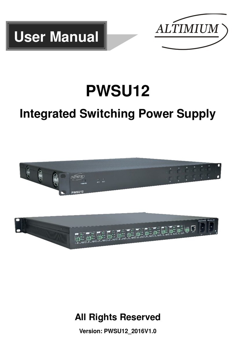
PDi PDI-772HE User manual

Communication
Systems Inc. PDI-772HE
AC CENTRAL POWER SUPPLY
Page 1 of 4
Better Solutions Are Within Reach™ INSTALLATION INSTRUCTIONS
PDi Communication Systems, Inc. 40 Greenwood Lane Springboro, Ohio 45066 USA PH +1-937-743-6010 FX +1-937-743-5664
This symbol is intended to alert the user that
parts inside the product are a risk of electric
shock to persons.
This symbol is intended to tell the user that
important operating and servicing
instructions are included with this product.
CAUTION ATTENTION
RISK OF ELECTRIC SHOCK
DO NOT OPEN
RISQUE DE CHOC ELECTRIETUE
NE PAS QUVRIR
TO REDUCE THE RISK OF ELECTRIC SHOCK, DO NOT REMOVE
COVER. NO USER-SERVICEABLE PARTS INSIDE. REFER
SERVICING TO QUALIFED SERVICE PERSONNEL.
AFIN DE REDUIRE LES RISQUES DE CHOC ELECTIQUE, NE PAS
RETIRER LE COUVERCLE. AUCUN ORGANE INTERNE NE PEUT
ETRE REPARE PAR L’UTILISATEUR. CONFIER L’APPAREIL A UN
DEPANNEUR QUALIFIE.
THIS INSTALLATION SHOULD BE MADE BY A QUALIFIED SERVICE PERSON AND SHOULD
CONFORM TO ALL LOCAL CODES. DO NOT ATTEMPT THIS INSTALLATION WITHOUT AN
ASSISTANT.
The PDI-772HE is a specialized power supply designed to power low-voltage AC small screen televisions and is
intended for use in a hospital, a nursing home, a medical-care center, or a similar health-care facility in which
installation is limited to a non-hazardous area in accordance with the National Electrical code, ANSI/NFPA70.
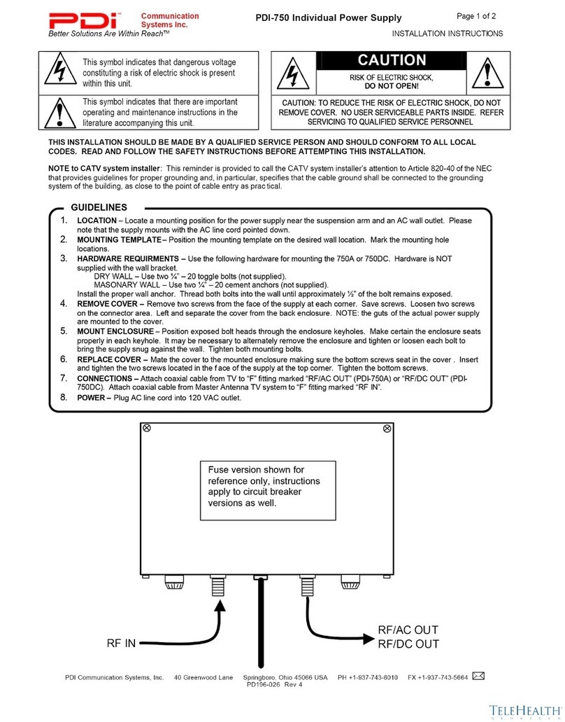
LOCATION – The supply is mounted in a utility or electrical closet near an AC wall outlet. Due to coaxial cable
length restrictions, select a location that limits the longest coaxial cable run distance between the supply and
furthest room to a maximum of 150 feet.
1. COOLING – Although this supply is engineered for high efficiency, observe these guidelines.
a. Select a location with a maximum ambient room temperature of less than 100°F.
b. Allow clearance areas on top, bottom and both sides. This clearance is required for cooling. Do
not cover or obstruct ventilation grills on the cabinet as this supply utilizes convection cooling. For
example, the supply should NOT be mounted in a drop ceiling due to the restricted airflow that
occurs in such a tight air space.
c. Do not route cables between the space in back of this wall mounted power supply. The back of the
supply must be kept clear to allow for convection air-cooling.
d. The supply under full load will generate approximately 110 watts of waste heat. Please consider
the location’s additional temperature rise caused by operation of this supply.
2. ELECTRICAL – This supply requires a 120 VAC circuit capable of supplying 10 amperes of current. Do NOT
use an extension cord with this power supply.
GUIDELINES
1. The central power supply is designed to mount on a wall in an
upright position with the power cord pointing down. The supply
should be positioned near an AC wall outlet. This unit is
convection cooled and requires clearance at the top, bottom,
and sides of the enclosure – see GUIDELINES for details.
2. Position the supply maintaining clearance. Mark the four
mounting hole locations on the wall.
3. Drill and install four, ¼-20 toggle bolts (not supplied) at each of
the mounting hole locations. Expose ½ inch of thread on each
bolt.
4. Center the supply over the ¼-20 bolts. Tighten.
WALL INSTALLATION

Communication
Systems Inc. PDI-772HE
AC CENTRAL POWER SUPPLY
Page 2 of 4
Better Solutions Are Within Reach™ INSTALLATION INSTRUCTIONS
PDi Communication Systems, Inc. 40 Greenwood Lane Springboro, Ohio 45066 USA PH +1-937-743-6010 FX +1-937-743-5664
TURN OFF UNIT WHEN SERVICING!
The supply is turned ON and OFF by
plugging or unplugging the power cord
plug at the AC wall outlet.
DO NOT USE THIS SUPPLY WITH
AN EXTENSION CORD.
TO PREVENT FIRE OR SHOCK
HAZARD, DO NOT EXPOSE THIS
APPLIANCE TO RAIN OR MOISTURE.
DO NOT COVER VENTILATION
GRILLS ON CABINET. ALWAYS
install front ventilation cover when unit
is in use.
IMPORTANT OPERATING INSTRUCTIONS
NOTE TO CATV SYSTEM INSTALLER: This reminder is provided to call the CATV system installer’s attention to
Article 820-40 of the NEC that provides guidelines for proper grounding and, in particular, specifies that the cable
ground shall be connected to the grounding system of the building, as close to the point of cable entry as practical.
RF SIGNAL INPUT: This a specialized power supply intended for use with multiple installation of commercial 9” or
similar coax powered hospital television receivers. This unit offers the following RF specifications:
1. RF CATV signal and 28VAC power supplied via a dedicated coaxial cable to each television.
2. This unit is RF passive and does not include any active amplification.
3. RF insertion loss is –14dbmv.
4. RF Bandpass is 10 to 1000 Mhz.
COAX CABLE SPECIFICATION: Due to long cable runs encountered in hospital installations, RG-6 coaxial cable
employing a solid copper center conductor and copper shield is required. Cable run lengths MUST NOT exceed
150 feet.
Required RG-6 coaxial cable numbers include Alpha 9804C (non-plenum), Belden 9248 (non-
plenum), West Penn 806 (non-plenum), or West Penn 25806 (plenum), which have been tested
with coax line-powered televisions. USE OF ANY OTHER CABLE NUMBER IS NOT
RECOMMENDED.
CABLING THE SUPPLY
This supply is provided with conduit knockouts on
the top, left side, and bottom of the cabinet as
cable entry points.
1. Disconnect the AC power cord from the wall
outlet.
2. Remove 4 screws from the face of the cabinet
and detach the ventilation cover exposing the
RF “F” connector row.
3. Connect the RF input cable to the bottom-
most “F” connector. Note: the insertion loss is
typically –14 dbmv. For a +10dbmv signal to
each television, an input RF level of +24dbmv
is suggested.
4. A dedicated home run of RG-6 coax cable to
each patient TV is required – Do NOT daisy
chain multiple televisions on a single cable.
Observe the following requirements:
a. Limit coax run lengths to less than
150 feet.
b. Use ONLY recommended cable
types as listed above under “COAX
CABLE SPECIFICATION”.
c. Wrench-tighten all cable
connections.
5. Use a Sharpie marker to identify each cable
on the “LOCATION” label next to the circuit
breaker field.
1 2 3 4 5 6 7 8 9 10 RF IN
1___
2___
3___
4___
5___
6___
7___
8___
9___
10__
CATV WIRING

Communication
Systems Inc. PDI-772HE
AC CENTRAL POWER SUPPLY
Page 3 of 4
Better Solutions Are Within Reach™ INSTALLATION INSTRUCTIONS
PDi Communication Systems, Inc. 40 Greenwood Lane Springboro, Ohio 45066 USA PH +1-937-743-6010 FX +1-937-743-5664
16. Power Lines
–
Do not locate an outside antenna system near overhead
power lines or other electric light or power circuit or where it can fall into such
lines or circuits. When installing an outside antenna system, extreme care
should be taken to keep from touching such power lines or circuits, as contact
with them might be fatal.
17. Overloading – Do not overload wall outlets and extension cords as they can
result in a risk of fire or electric shock. Do not use this supply with an
extension cord.
18. Object and Liquid Entry – Never push objects of any kind into this supply
through openings as they may touch dangerous voltage points or short out
parts, resulting in a fire or electric shock. Never spill liquid of any kind on the
supply.
19. Servicing – Do not attempt to service this supply yourself as opening or
removing covers may expose you to dangerous voltage or other hazards.
Refer all servicing to qualified service personnel.
20. Damage Requiring Service - Unplug this supply from the wall outlet and refer
servicing to qualified service personnel under the following conditions:
a. When the power-supply cord or plug is damaged or cut.
b. If liquid spills or objects fall into the supply.
c. If the supply is exposed to rain or water.
d. If the supply does not operate normally by following the operating
instructions. Adjust only those controls that are covered by the
operating instructions. An improper adjustment of other controls may
result in damage and will often require extensive work by a qualified
technician to restore the supply to its normal operation.
e. If the supply is dropped or the cabinet is damaged.
f. When the supply exhibits a distinct change in performance, this
indicates a need for service.
21. Replacement Parts – When replacement parts are required, be sure the
service technician uses replacement parts specified by the manufacturer or
which have the same characteristics as the original part. Unauthorized
substitutions may result in fire, electric shock or other hazards.
22. Safety Check – Upon completion of any service or repairs to this supply, ask
the service technician to perform safety checks to determine that the supply is
in proper operating condition.
23. Wall or Ceiling Mounting – This supply should be mounted to a wall only as
recommended by the manufacturer. Do not mount this supply to or in a
ceiling.
24. Periodic Maintenance – This supply does not require periodic maintenance
other than cleaning.
25. Heat – This supply should be situated away from heat sources such as
radiators, heat registers, stoves, or other products (including amplifiers) that
produce heat.
Antenna
Lead - In
Wire
Antenna
Discharge Unit
(NEC Section 810-20)
Grounding Conductors
(NEC Section 810-21)
Ground Clamps
Power Service Grounding
Electrode System
(NEC ART 250, Part H)
Electric
Service
Equipment
NEC - NATIONAL ELECTRICAL CODE
Figure 1.
S2892A
1. Read Instructions
–
Read all of the safety and operating
instructions before you operate this television.
2. Keep Instructions – Keep the safety and operating instructions
for future reference.
3. Heed Warnings – Adhere to all warnings on the appliance and
in the operating instructions.
4. Follow Instructions – Follow all operating and use instructions.
5. Cleaning and Disinfecting – Unplug this supply from the wall
outlet before cleaning. Do not use liquid cleaners or aerosol
cleaners. Use a damp cloth for cleaning. Do not immerse this
supply in water.
6. Attachments – Do not use attachments not recommended by
the manufacturer. They may be hazardous.
7. Water and Moisture – Do not use this supply near water – for
example, near a bathtub, washbowl, kitchen sink, or laundry tub,
in a wet basement, or near a swimming pool, etc. Do not use
this supply outdoors.
8. Accessories – Do not place this supply on a cart, stand, tripod,
bracket, or table. The supply may fall, causing serious injury to
a child or adult and serious damage to the appliance. Use this
supply only with a mount recommended by the manufacturer, or
sold with the supply. Any mounting of the appliance should
follow the manufacturer’s instructions and should use a
mounting accessory recommended by the manufacturer.
9. Supply and Cart – This supply is designed for permanent
mounting. DO NOT use with a cart.
10. Ventilation – Slots and openings in the cabinet are provided for
ventilation, to ensure reliable operation of the supply, and to
protect it from overheating. Do not block or cover these
openings. Do not block the openings by placing the supply on a
bed, sofa, rug, or other similar surface. Do not place this supply
near or over a radiator or heat register. Do not place this supply
in a built-in installation such as a bookcase or rack.
11. Power Sources – Operate this supply only from the type of
power source indicated on the marking label. If you are not sure
of the type of power supplied to your health care facility, consult
your dealer, facility maintenance, or local power company.
12. Grounding – This supply incorporates a three-wire grounding-
type plug, a plug having a third (grounding) pin. This plug will
only fit into a grounding-type power outlet. This is a safety
feature. If you are unable to insert the plug into the outlet,
contact your electrician to replace your obsolete outlet. Do not
defeat the safety purpose of the grounding-type plug.
13. Power Cord Protection – Route power supply cords so that
they are not likely to be walked on or pinched by items placed
upon or against them, paying particular attention to cords at
plugs, convenience receptacles, and the point where they exit
from the appliance.
14. Outdoor Antenna Grounding – If you connect an outside
antenna or cable system to the supply, be sure the antenna or
cable system is grounded so as to provide some protection
against voltage surges and built-up static charges. Section 810
of the National Electrical Code, ANSI/NFPA No. 70, provides
information with respect to proper grounding of the mast and
supporting structure, grounding of the lead-in wire to an antenna
discharge unit, size of grounding conductors, location of antenna
discharge unit, connection to grounding electrodes, and
requirements for the grounding electrode. (See Figure 1).
15. Lightning – For added protection during a lightning storm, or
when it is left unattended and unused for long periods of time,
unplug it from the wall outlet and disconnect the antenna or
cable system. This will prevent damage to the supply due to
lightning and power-line surges.
IMPORTANT SAFETY INSTRUCTIONS

Communication
Systems Inc. PDI-772HE
AC CENTRAL POWER SUPPLY
Page 4 of 4
Better Solutions Are Within Reach™ INSTALLATION INSTRUCTIONS
PDi Communication Systems, Inc. 40 Greenwood Lane Springboro, Ohio 45066 USA PH +1-937-743-6010 FX +1-937-743-5664
SYMPTOMS POSSIBLE SOLUTIONS
TV does not operate
• Make sure the power supply cord is plugged in.
• Try another AC outlet.
• Power is off, check circuit breaker.
• Wrong Coax Cable used – See WRONG COAX below.
Poor reception or No picture
• Station or CATV experiencing problems, tune to another station.
• Check CATV connections. Check CATV signal level.
• Check for sources of possible interference.
Power supply trips circuit breakers
• Shorted Coax. Check coax.
• Shorted connection. Check CATV connections.
• Wrong Coax Cable used – See WRONG COAX below.
Picture wobbles or drifts
• Station or CATV experiencing problems, tune to another station.
• Ground loop caused by poor grounding. Check CATV connections and
grounds.
• Wrong Coax Cable used – See WRONG COAX below.
TROUBLESHOOTING
The NUMBER ONE installation problem involves use of the WRONG type of coax – one that employs a copper-
clad steel center conductor. Remember, that the coax must carry not only CATV RF signal, but also AC power
hundreds of feet from the central power supply to each television location. Unfortunately, the copper-clad steel
center coax offers 10 times the resistance to that of a pure solid copper center conductor style coax. In other
words, a 100-foot length of copper-clad steel coax electrically looks equivalent to a 1,000-foot pure copper cable.
The steel cable offers too much resistance to the low frequency AC power current. The typical problems are those
associated with low voltage – the TV operates erratically or not at all.
DO NOT USE copper-clad steel center conductor style coax cable. You can easily be fooled since the steel center
conductor is platted with a copper cladding – it looks like copper. As a test, touch a magnet to the center
conductor. If it sticks, you have steel inside. DON’T USE IT!
The required RG-6 coaxial cable numbers include:
• Alpha 9804C (non-Plenum)
• Belden 9248 (non-plenum)
• West Penn 806 (non-plenum)
• West Penn 25806 (plenum)
These coax cables have been tested with coax line-powered televisions. USE OF ANY OTHER CABLE NUMBER
IS NOT RECOMMENDED.
WRONG COAX
PDI Communication Systems
40 Greenwood Lane
Springboro, Ohio 45066
Internet: http://www.pdiarm.com
Phone: 937.743.6010 Fax: 937.743.5664
Sales: sales@pdiarm.com
CONTACT INFORMATION
Table of contents
Other PDi Power Supply manuals

