PDK PDR1000 User manual

PDR1000
Digital Pressure Gauge
Users Manual
25

26
Table of Contents
1. General Introduction ……………………………………………………………………………………… 27
2. Abbreviations & Initials ………………………………………………………………………………… 28
3. Introduction ………………………………………………………………………………………………… 28
3.1 Specification …………………………………………………………………………………… 29
3.2 Front / Back panel …………………………………………………………………………… 30
4. Operation ………………………………………………………………………………………………… 32
4.1 Key Operation
…………………………………………………………………………………… 32
4.1.1 Power On …………………………………………………………………………… 32
4.1.2 PEAK …………………………………………………………………………………… 32
4.1.3 UNIT …………………………………………………………………………………… 32
4.1.4 ZERO …………………………………………………………………………………… 32
4.1.5 Back Light …………………………………………………………………………… 33
4.2 Menu/Function Select ……………………………………………………………………… 33
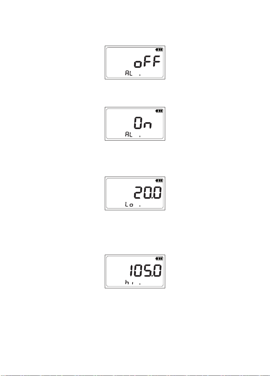
4.2.1 Alarm …………………………………………………………………………………… 33
4.2.2 Pressure Switch Test ……………………………………………………………… 35
4.2.3 Calibration …………………………………………………………………………… 38
4.2.4 Baud Rate …………………………………………………………………………… 39
4.2.5 RS232 Communication …………………………………………………………… 40
4.2.6 Auto Power Off …………………………………………………………………… 42
4.2.7 Data Logger ………………………………………………………………………… 43
4.2.8 Storage Data Clear ……………………………………………………………… 45
4.2.9 End …………………………………………………………………………………… 45
5. Maintenance Adjustments and Calibration ……………………………………………………… 46
5.1 Zero Adjustment ……………………………………………………………………………… 46
5.2 Pressure Calibration …………………………………………………………………………… 46
5.3 Analog Output Calibration ………………………………………………………………… 46
6. Troubleshooting ……………………………………………………………………………………………… 47
7. Appendix
…………………………………………………………………………………………………… 48
7.1. Warranty Statement
………………………………………………………………………… 48
7.2. Accessory
……………………………………………………………………………………… 48
7.3. Table of pressure unit conversion ……………………………………………………… 49

1. General Introduction
Manual Conventions
This manual is intended to provide the user with the basic information necessary to operate a
PDR1000 (Digital Pressure Gauge). It also includes a great deal of additional information provided
to allow you to optimize PDR1000 use and take full advantage of its many features and functions.
“Caution” is used in throughout the manual to identify conditions or actions that could
cause harm to the PDR1000 or user of the PDR1000.
“Note” is used throughout the manual to identify operating and applications advice
and additional explanations.
High pressure liquids and gases are potentially hazardous. Energy stored in these liquids and
gases can be released unexpectedly and with extreme force. High pressure systems should be
assembled and operated only by authorized personnel who have been instructed in proper safety
practices.
27

2. Abbreviations & Initials
Units & Words Keys Units & Words Keys
kPa kilopascal a absolute
MPa megapascal g gauge
hPa hectopascal PEAK peak
mbar millibar Hi high
bar bar Lo low
psi pounds per square inch MAX maximum
mmH2O millimeter of water MIN minimum
mmHg millimeter of mercury Hold Hold
inH2O inch of water mA Milliampere
inHg inch of mercury Alarm
atm atmosphere V Voltage
kgf/cm2kilogram force per square
centimeter REM serial interface
communication standard
3. Introduction
The PDR1000 Series Reference Digital Pressure Gauges (the Product) are high accuracy digital
pressure test gauges. PDR1000 has best performance that can measure precision pressure from
-100 kPa to 500 MPa without a separate external power supply in anytime any place, including
on-site and laboratory. Also PDR1000 equipped solid and stylish aluminum outer casing for
durability.
PDK produced PDR1000 with PDK’s unique pressure calibration and production technology
that has best performance in its class. PDR1000 is digital pressure gauge for precise pressure
measurement and test with Built-in various features.
Simply use buttons on front panel to operate and select various functions and external power
input section, analog output port (1 to 5 VDC), and communication port (RS232) and batteries
change socket on rear panel.
Combine pressure comparator or hand pump for using pressure calibrator in field and calibration
lab for simple pressure measurement and calibration provides an excellent solution.
28

3.1 Specification
Pressure Range
Accuracy
Over Pressure limit
Bust Pressure
Pressure Unit
Workable
Temperature Range
Storage
Temperature Range
Temperature
Compensation Range
RS232 Communication
Power Requirement
Media of Use
Display
Display Speed
Analog Output
Pressure Port
Weight
Size
Data Logging
-100 kPa to 150 MPa 0 to 250 MPa 0 to 500 MPa
Gauge : ±0.025% F.S
Absolute / Compound : ±0.05% F.S ±0.05% F.S ±0.1% F.S
** Included Nonlinearity, Hysteresis, Repeatability, errors for
-10 ~ 50 ℃ Temperature range
150 % of full scale
kPa, MPa, kg/cm2, psi, mbar, bar, inHg, inH2O, mmH2O, mmHg, atm
-20 ~ 70 ℃
-30 ~ 80 ℃
-10 ~ 50 ℃
Provide Commands in manual,
Available to use private communication cable (Option)
AA Alkaline battery 3ea,
Hours of battery use approximately 1000 hours
External power supply(Option, 12~24 VDC),
Gas & Liquid (Only Gas available below 100 kPa)
5 Digits, Backlight On/Off, Auto Off
3 times / Second
(10 times automatic change if Peak function use)
1 - 5 VDC (Must use external power supply), 0.1% Accuracy
(Option : 4-20mA , 0-5VDC , 0-10VDC)
1/4" NPT M, 1/4" PF (G), 1/4" PT (R), 9/16" UNF Cone Threaded
(HF4/AF250C, 100 MPa / 150 MPa)
530 g
Dia. 110 (W) mm x 38 (D) mm x 150 (H) mm Included Pressure Port
1 time / 1, 3, 5, 30, 60 second, Store Max 3000 data
Refer to pressure type and range in catalog.
29

3.2 Front / Back Panel
3.2.1 On / Off Key
PDR1000 Power On/Off key
3.2.2 PEAK/MENU Mode key
3.2.3 UNITS / Analog out / Down Key
3.2.4 ZERO / Up Key
PEAK
MENU
UNITS ZERO
Photo 1. PDR1000 Front / Rear Panels Photo
Figure 1. Buttons
Peak shows maximum and minimum pressure value.
Menu makes selection and set for Alarm, Switch, CAL, Baud Rate, Auto Power Off, and Data
Logger. Saved peak value will be clear when PDR1000 turns off.
Change the pressure units and On/Off for Analog output.
In configure mode, push Down key to move backward through the menus.
(Analog output function is only available when external power supply used)
Zeroing pressure offset value.
Pressure Switch On/Off, Peak value will be clear when Peak mode.
In configure mode, push Up key to move forward through the menus.
30

3.2.5 Back Light / Enter Key
Backlight On/Off
Use Enter key to set up the Menu.
[ D-Sub 9 Pin Map ]
Figure 2. RS-232 Port
Table 1. Pin outs
5
6789
4 3 2 1
Pin No Description Note
1GND
2RX RS232
3TX
4Analog Out+ Analog Output
5GND
6Ext. Switch In
7Alarm Out
8Ext. Power + External Power
9Ext. Power -
31

4. Operation
4.1 Key Operation
4.1.1 Power On
: Push POWER key on front panel to power on.
Screen at no pressurize or Zero set.
4.1.2 PEAK / MENU
: Peak shows maximum and minimum pressurized value on PDR1000.
Push PEAK/MENU key indicates Hi for maximum pressurized value.
Push PEAK/MENU key again, indicates Lo for minimum pressurized value.
Push PEAK/MENU key again, return to the current pressure value.
4.1.3 UNITS
: This function can change engineering units on PDR1000.
When push UNIT key engineering units will change as following steps.
MPa →mbar →bar →inH2O →mmH2O →inHg →mmHg →kgf/cm² →atm
→psi →kPa →MPa
To set Analog Out function, push UNIT key for 2 seconds.
(It only operates when external power supply connected)
4.1.4 ZERO
: This function is zeroing the PDR1000.
ZERO
PEAK
MENU
UNITS
For Gauge mode push ZERO key for 2 seconds under normal atmosphere condition. For the
32
psi
%
g
0

4.1.5 Back Light / Enter
: Push to turn on the backlight. Push again to turn off the backlight.
4.2 Menu/Function Select
4.2.1 Alarm
Alarm function must need external power supply. (Figure 3 reference)
Figure 3. Alarm Setup flowchart
Absolute mode, make vacuum state (under 1 × 10⁻² torr) then ZERO key for 2 seconds to zeros
the display. Zero key can clear the Peak Hi Low values when Peak mode. Also it can select the
set up when Pressure Switch mode.
Push Enter key for 2 seconds to start or stop for Data Logger function.
To set Data Logger function, turn on the Data Logger function on configuration menu.
Push PEAK/MENU key for 2 seconds to go to setup and configuration menus.
Push power key to go to End Menu or Push PEAK/MENU key to set other function settings after
Menu function sets.
Analog out, Alarm : These function must need external power supply to operate.
33
ZERO
psi
%
g
0
psi
%
g
0
Alarm
Lo
psi
%
g
0
Alarm
Hi
psi
%
g
0
Alarm
psi
%
g
0
Alarm
psi
%
g
0
Alarm
psi
%
g
0
Alarm
%
0
psi g
PEAK
MENU

First screen of Alarm function page. Press UP key to turn Alarm On.
Alarm On screen on above. Press Enter key to save Alarm On status then Alarm Low value
setup screen shows with blink.
Alarm Low value setup screen on above. Digits on above screen is percentage value of PDR1000
Full Scale. Push ZERO key and UNITS key to change percentage value.
After push Enter key to save Alarm Low value, Alarm Hi value setup screen shows with blink.
Alarm Hi value setup screen on above. Digits on above screen is percentage value of PDR1000
Full Scale. Push ZERO key and UNITS key to change percentage value.
After push Enter key to save Alarm Hi value, Electric Contact Alarm Signal setup screen shows
with blinking.
34
psi
%
g
0
Alarm
Lo
psi
%
g
0
Alarm
Hi
psi
%
g
0
Alarm
psi
%
g
0
Alarm

Electric Contact Alarm Signal setup screen on above. Push ZERO key to select Normal Close or
Normal Open status set. Push Enter key to save Electric Contact Alarm Signal setup.
< Electric Contact Alarm Signal operation mode >
4.2.2 Pressure Switch Test
Figure 4. Switch test Setup flowchart
< Normal Open (N_O) >
5V
HiLo
0V0V
5V
+ Pressure- Pressure
< Normal Close (N_C) >
5V5V
HiLo
0V0V
+ Pressure- Pressure
35
psi
%
g
0
Alarm
psi
%
g
0
Alarm
psi
%
g
0
psi
%
g
0
psi
%
g
0
psi
%
g
0
%
0
psi g
psi
%
g
0
PEAK
MENU
ZERO

Pressure Switch Test function is that receive and indicate Electric contact signal (On/Off) from
Pressure Switch.
Push PEAK/MENU key for 2 seconds to go to Menu function then select Switch Menu screen.
Push ZERO key to set Switch On or Off. Push Enter key to save Switch status then escape the
Switch Menu.
< Operation Mode >
1) Operation for External Pressure Switch Off to On
Pressure Switch function “ON” screen on above.
If PDR1000 received external electric contact signal (Switch turns Off to On)
2) Operation for External Pressure Switch On to Off
Switch icon will change from open to close ( ) then pressure value will be hold status
with “Hold” icon blinking. Even supply pressure changed, Pressure value will keep hold until push
ZERO key. Pressure changes can check via percentage section on the bottom side of screen.
This case is that external electric contact open to close – in other words switch status changed
from Off to On.
The other case is switch turns from On to Off.
If it connect with Switch “On” status, it will be “1)” operation because initial status of Switch function
is open icon as ( ).
If push ZERO key, it will be same screen as on below screen.
36
MPa
%
g
050
MPaHold
%
g
050

If PDR1000 received external electric contact signal (Switch turns On to Off), Switch icon will
change from close to open ( ) then pressure value will be hold status with “Hold” icon
blinking.
Even supply pressure changed, Pressure value will keep hold until push ZERO key.
Pressure changes can be checked via percentage section on the bottom side of screen.
<Hysteresis function>
Apply Switch function operation with Switch “On” status then connect External Pressure Switch
to PDR1000.
If pressure value reach the Pressure Switch set value, display pressure value will be hold then
copy down the held pressure value.
Push ZERO key to release the held pressure value then depressurize, Electronic contact on
Pressure Switch will reverse and locked up the display value.
Pressure Switch Hysteresis value is difference between when pressurize then electronic contact
changed and when depressurize then electronic contact changed.
< Normal Close type > PSV
ON
OFF
Hys + Pressure- Pressure
PSV : Pressure safety Valve
Hys : Hysteresis Value
37
MPa
%
g
050
MPaHold
%
g
050

4.2.3 Calibration
Figure 5. Calibration flowchart
Calibration function can adjust Zero and Full Scale value.
Zero Adjustment – Push Enter key for 2 seconds to set Zero value. If Zero set finished, display
shows corrected Zero.
Zero adjustment should be adjusted within ±10% of full scale.
This function is Full Scale pressure value adjustment.
Push Enter key for 2 seconds to change Full Scale value. After Full Scale adjustment finished,
< Normal Open type >
PSV
ON
OFF
Hys + Pressure- Pressure
PSV : Pressure safety Valve
Hys : Hysteresis Value
38
psi
CAL
g
050
100
CAL
psi
CAL
g
0
(Caution) Do not pressurize quickly during Pressure Switch Test.
psi
CAL
g
050
100
CAL
psi
%
g
0
psi
CAL
g
0
%
0
psi g
PEAK
MENU

4.2.4 Baud Rate
Figure 6. Baud Rate setup flowchart
This function can set Baud Rate for RS232 Communication.
display shows current adjusted pressure value. Full Scale adjustment should be adjusted within
±10% of full scale value and displayed full scale value adjust with Pressure controller/calibrator
or Piston gauge.
Push PEAK/MENU key for 2 seconds to select Menu function. Push again PEAK/MENU key to
select Baud Rate function then push ZERO key to choose Baud Rate.
39
psi
%
g
0
REM
%
0
psi g
psi
%
g
0
psi
%
g
0
REM
psi
%
g
0
REM
PEAK
MENU
ZERO
psi
%
g
0
REM
psi
%
g
0
REM
psi
%
g
0
REM
psi
%
g
0
REM

40
4.2.5 RS232 Communication
1. Data Request Configuration
5 Byte 1 Byte 3 Byte 1 Byte 4~6 Byte 1 Byte
ID BL C1 BL C2 LF
3. Data Indication
5 Byte 1 Byte 3 Byte 1 Byte 4 Byte 1 Byte
ID BL C1 BL C2 CR
CR[001] GET INFO
[001] ID NO : [001]
Model Name : Jain- 2 KD
Serial_No. : 2020G01-0001
Sensor Range : -2.0 ~ 2.0 K{ETX}
< Response Example >
2. Data Response Configuration
1 Byte 5 Byte 1 Byte 1 Byte 1 Byte
STX ID D1 CR LF EOT
ID will shows as [xxx], D1 has up to 25 Bytes of output data.
<RS232 Communication Set>
Baud Rate : 19200 Data Bit Length : 8 bit
Stop Bit : 1 bit Parity : None
Data flow control : N/A Data Code : ASCII code
<Description>
BL : Blank C1 : Command1
LF : Line Feed
CR : Carriage Return STX : Start of text
D1 : Data EOT : End of text
C2 : Command2

41
6. Data Logger function
5 Byte 1 Byte 3 Byte 1 Byte 6 Byte 1 Byte
ID BL C1 BL C2 CR
[001] GET LOGALL CR
4. Continuous sample Pressure value, Temperature value
5 Byte 1 Byte 3 Byte 1 Byte 6 Byte 1 Byte
ID BL C1 BL C2 CR
[001] GET MDAUTO
[001] P = -0.00136, T = 24.95
[001] P = -0.00136, T = 24.95
[001] P = -0.00132, T = 24.95
[001] P = -0.00126, T = 24.95
< Response Example >
CR
5. Sample one Pressure value, one Temperature value
5 Byte 1 Byte 3 Byte 1 Byte 6 Byte 1 Byte
ID BL C1 BL C2 CR
[001] GET MDMANU
[001] GET MANU
[001] P = -0.00136, T = 0.00,
[001] GET MANU
[001] P = -0.00122, T = 0.00,
[001] GET MANU
[001] P = -0.00115, T = 0.00,
< Response Example >
CR

4.2.6 Auto Power Off
Figure 7. Auto Power Off setup flowchart
Push PEAK/MENU key for 2 seconds to select Menu function then push PEAK/MENU key to
choose Auto Power Off function. Push ZERO key to set the necessary interval.
Default Auto Power Off time set is 10 minutes.
Auto Power Off function can set Auto Off. This function can use after Auto Power Off function
on. Choose one of 5 min, 10 min, 20 min, and 30 minutes.
42
%
0
psi g
psi
%
g
0
psi
%
g
0
PEAK
MENU
psi
%
g
0
psi
%
g
0
psi
%
g
0
psi
%
g
0
psi
%
g
0
ZERO

43
4.2.7 Data Logger
Figure 8. Data logger setup flowchart
Push PEAK/MENU key for 2 seconds to select Menu function.
Push PEAK/MENU key to select Data Logger function.
Push ZERO key to set Data Logger function.
Push ENTER key to save Data Logger status.
Push ENTER key to go to next Menu when Data Logger off, push ENTER key to set Data Logger
function save and time mode when Data Logger On.
psi
%
g
0
psi
%
g
0
psi
%
g
0
psi
%
g
0
psi
%
g
0
psi
%
g
0
%
0
psi g
psi
%
g
0
psi
%
g
0
psi
%
g
0
psi
%
g
0
psi
%
g
0
psi
%
g
0
psi
%
g
0
psi
%
g
0
ZERO

44
Push ZERO key to save Data Logger Data save time.
Select Data save time and push ENTER key to save then go to Data save page.
Figure 9. Data storage address set up
Long push ZERO key to select start page when Data Logger function data save. It can choose page
1 to page 30. Choose and select Data save page then push ENTER key to save.
To set rest of Menu function, push PEAK/MENU key again to set other various functions. Data
Logger function can save 100 sample data per page.
Data saved value are average and max.
Push ENTER key for 2 seconds to stop Data Logger function.
Available to check the data via RS232 Communication.
psi
%
g
0
psi
%
g
0
psi
%
g
0
Push PEAK/MENU key a few times to select End Menu or push POWER key to select End Menu.
After Menu sets then use Logger function, push ENTER key to 2 seconds then display shows “Log”
with blinking.
At this moment, unable to use RS232 Communication because PDR1000 is saving pressure value
at the same time.
psi
%
g
0
psi
%
g
0
psi
%
g
0
psi
%
g
0
psi
%
g
0
psi
%
g
0
Table of contents
Other PDK Measuring Instrument manuals
Popular Measuring Instrument manuals by other brands

Keba
Keba KeMes A2 Series operating instructions

Ludlum Measurements
Ludlum Measurements 2363 manual

MessKonzept
MessKonzept FTC300 operating manual

Elcometer
Elcometer 406L operating instructions

Tractel
Tractel dynafor HHD Installation, operating and maintenance manual

Siemens
Siemens sitrans PROBE LU instruction manual

Reed Instruments
Reed Instruments LM-81HT instruction manual

SMS
SMS smart meter installation guide

Krystufek
Krystufek PANCONTROL PAN Multitacho manual

Emerson
Emerson Rosemount 6888C manual

PCB Piezotronics
PCB Piezotronics IMI SENSORS 624B01 Installation and operating manual

wtw
wtw 2F30-100 operating manual