Peak Scientific Precision 500 User manual
Fountain Crescent T: +44 (0)141 812 8100 Part No. IG-Precision
Inchinnan Business Park F: +44 (0)141 812 8200 Rev. 01
Inchinnan, PA4 9RE W: www.peakscientific.com
Scotland, UK E: info@peakscientific.com Page Page 1 of 8
x 1
x 1
x 1
Installation Guide – Precision 500 Generator 110V
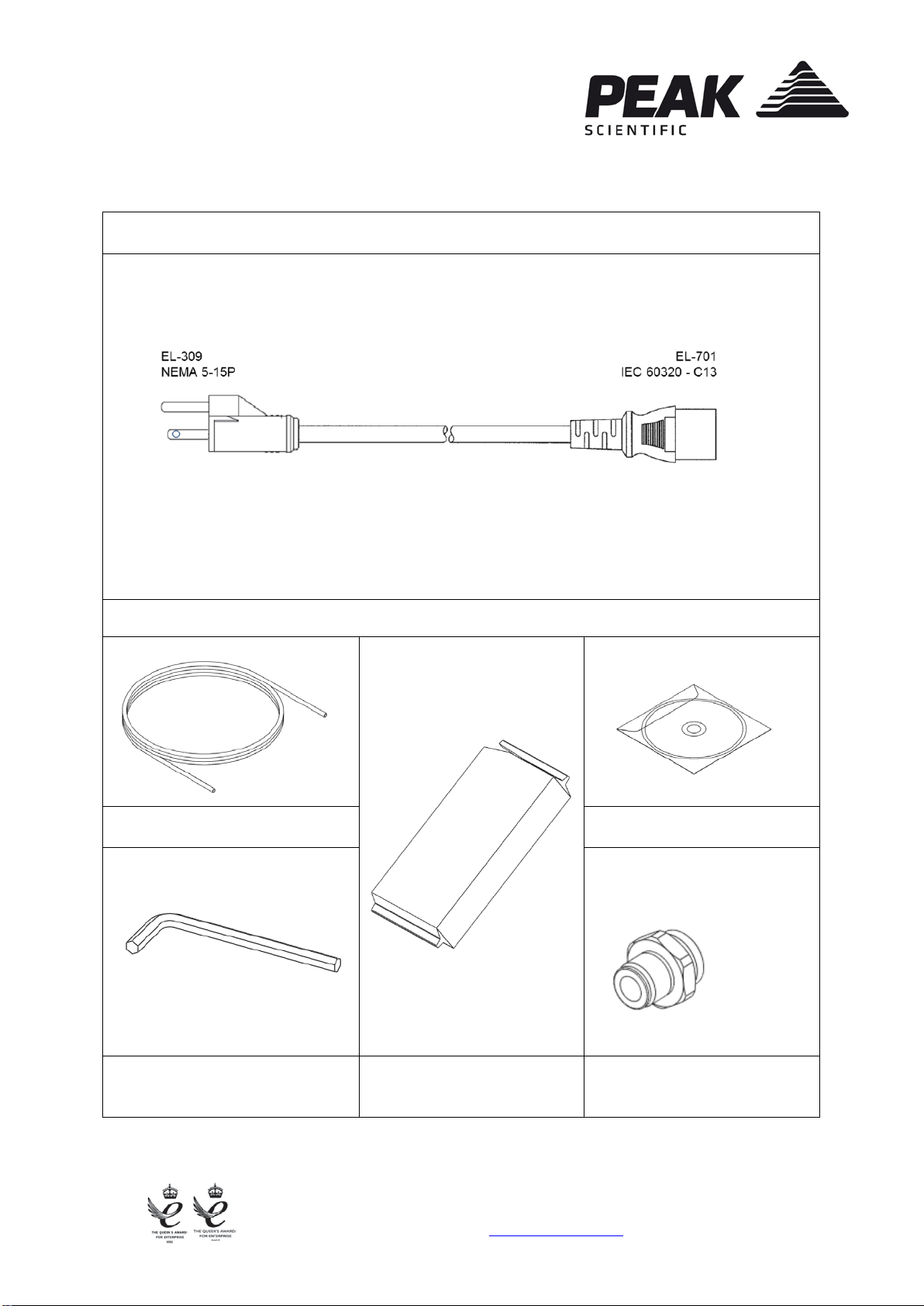
FITTINGS KIT
Mains Cable – US
⅜” Tygon Tube CD containing User Manual
2.5mm Hex Key Resin Column Re-fill Barbed Fitting
x 1m
x 1
Fountain Crescent T: +44 (0)141 812 8100 Part No. IG-Precision
Inchinnan Business Park F: +44 (0)141 812 8200 Rev. 01
Inchinnan, PA4 9RE W: www.peakscientific.com
Scotland, UK E: info@peakscientific.com Page Page 2 of 8
INSTALLATION
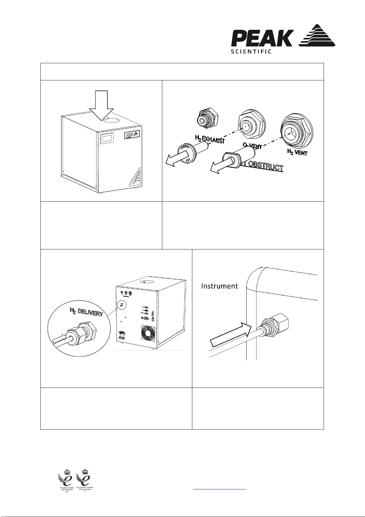
1.
2.
Unpack the generator from the
shipping crate and position on a flat
surface, in desired area.
Ensure the ¼” and ⅜” plugs have been removed
from the O2 and H2vents, located at the rear of the
generator.
3.
4.
Connect the ⅜” tubing, contained in the fittings
kit, to the H2 Delivery port at the rear of the
generator.
Connect the other end of the tubing to the
Application.

Fountain Crescent T: +44 (0)141 812 8100 Part No. IG-Precision
Inchinnan Business Park F: +44 (0)141 812 8200 Rev. 01
Inchinnan, PA4 9RE W: www.peakscientific.com
Scotland, UK E: info@peakscientific.com Page Page 3 of 8
5.
6.
Connect an external supply of deionised
wa
ter to the Fill connection at the rear of the
unit, using the supplied tubing. Water
loading takes place automatically by means
of a water pump located within the
generator.
Select the mains cable from the fittings kit and
plug the IEC 60320/C13
socket into the mains
input at the rear of the generator.
7.
8.
Plug the mains cable into an appropriate
110VAC 50/60Hz single phase power
supply.
Turn the generator on, using the switch on the
back of the unit.
110VAC 50/60Hz
Fountain Crescent T: +44 (0)141 812 8100 Part No. IG-Precision
Inchinnan Business Park F: +44 (0)141 812 8200 Rev. 01
Inchinnan, PA4 9RE W: www.peakscientific.com
Scotland, UK E: info@peakscientific.com Page Page 4 of 8
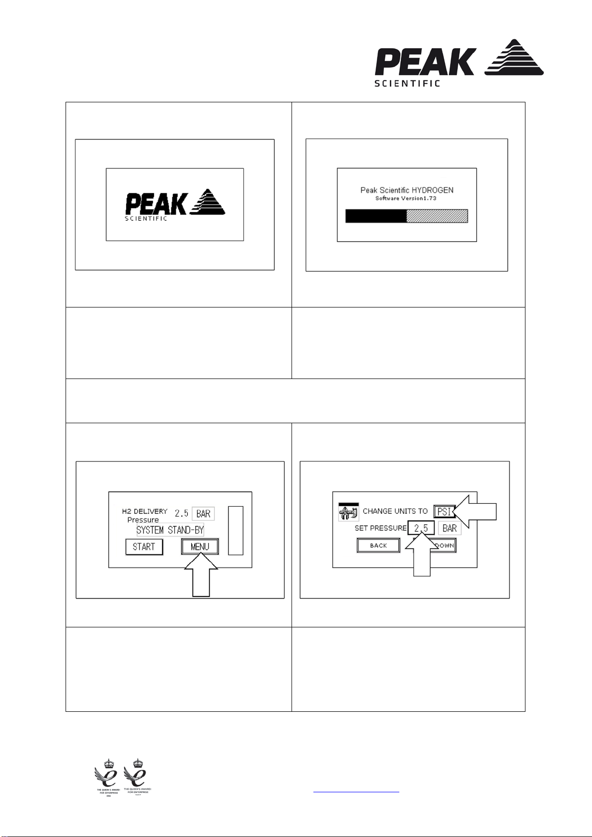
9.
10.
The touch HMI screen will illuminate and
the start screen will be displayed. The system will now run diagnostics and a
leak detection test.
* NOTE * If diagnostics are unsuccessful, an alarm will sound and a red failure screen
will be displayed, complete with a mute button. The user is prompted at this point to
contact their Peak service provider.
11.
12.
Upon completion of the diagnostic checks,
the home screen will be displayed. The user
should now select MENU.
The desired unit of measure and pressure
should now be selected, by pressing the unit
or pressure displayed.

Fountain Crescent T: +44 (0)141 812 8100 Part No. IG-Precision
Inchinnan Business Park F: +44 (0)141 812 8200 Rev. 01
Inchinnan, PA4 9RE W: www.peakscientific.com
Scotland, UK E: info@peakscientific.com Page Page 5 of 8
13.
14.
Once the desired unit of measure and
pressure have been selected, pressing
BACK will return the user to the home
screen.
Pressing START will start the supply to the
application. The unit may take a few minutes
to adjust to the desired pressure.
15.
16.
The unit will now maintain the desired
pressure, while the application is supplied.
The system can be stopped at any time by
pressing STOP. This will return the generator
to Standby mode.
Fountain Crescent T: +44 (0)141 812 8100 Part No. IG-Precision
Inchinnan Business Park F: +44 (0)141 812 8200 Rev. 01
Inchinnan, PA4 9RE W: www.peakscientific.com
Scotland, UK E: info@peakscientific.com Page Page 6 of 8
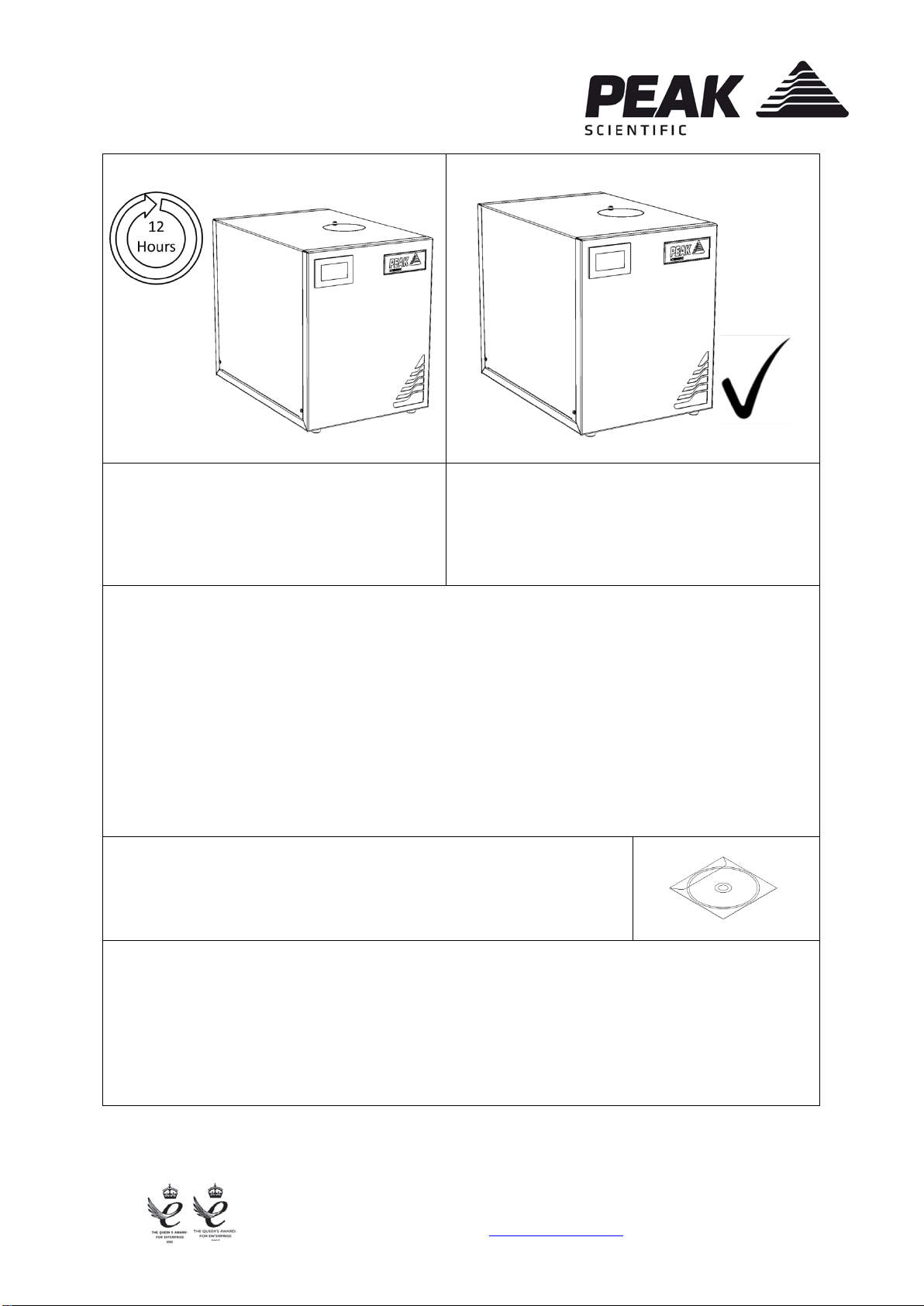
17.
18.
It is recommended that the unit is left to
run for 12 hours before utilisation.
CONGRATULATIONS
Your PEAK SCIENTIFIC gas generator is now
fully installed, operational and ready to supply
gas on demand to your instrument.
General Notes
* The generator will operate on voltages of 110VAC +/- 10%. This means it will operate
between 103V and 126V. It is okay to operate the generator on a mains voltage
between 103V and 126
V for a short period of time, however we would recommend fitting
the listed transformer at your earliest convenience.
For all other technical specifications, operating instructions, service
requirements, contact details and trouble shooting, please refer to
the user manual contained on the CD supplied in the fittings kit.
Please keep this for future reference.
19.
It is very important to register your generator with PEAK SCIENTIFIC. This will initiate
your warranty entitlement. Please use the form on the next page to register your
generator. You will need the generators serial number which can be found on the serial
label on the rear of the generator.

Fountain Crescent T: +44 (0)141 812 8100 Part No. IG-Precision
Inchinnan Business Park F: +44 (0)141 812 8200 Rev. 01
Inchinnan, PA4 9RE W: www.peakscientific.com
Scotland, UK E: info@peakscientific.com Page Page 7 of 8
IMPORTANT DOCUMENT
S
Warranty Entitlement
To register your generator for your warranty entitlement, send the completed form
to Peak Scientific by:
•
Email
warranty@peakscientific.com
•
Online
http://www.peakscientific.com/service-and-support/warranty_registration
•
•
Phone
F
ax
+44 (0)141 530 4185
+44 (0)141 812 8200
PRODUCT WARRANTY REGISTRATION
COMPANY:
CONTACT NAME:
ADDRESS:
EMAIL ADDRESS:
CITY/TOWN:
GENERATOR SERIAL NUMBER:
POSTCODE:
COUNTRY:
MODEL TYPE:
TELEPHONE:
INSTALLATION DATE (DD/MM/YYYY):
Important Please Note:
You have 1 month to register your Peak Scientific product from the date of shipment.
If you wish to defer installation of your generator you must notify Peak Scientific within 1 month of
the shipment date. This can be done by emailing warranty@peakscientific.com Once registered the
warranty will be honoured for a period of 12 months after the installation date.
For any generators that remain unregistered the warranty will begin from date of shipment.
Thank you on behalf of Peak Scientific.

Fountain Crescent T: +44 (0)141 812 8100 Part No. IG-Precision
Inchinnan Business Park F: +44 (0)141 812 8200 Rev. 01
Inchinnan, PA4 9RE W: www.peakscientific.com
Scotland, UK E: info@peakscientific.com Page Page 8 of 8
Expanding Capacity
If multiple
Precision 500 generators are being installed they must be connected as shown in
the image below.
The units must be connected together via the ‘Master’ port on the first Precision 500, and the
‘Slave’ port at the rear of the next Precision 500 unit.
The first Precision 500 unit is automatically defined as the Master, and before the
connections are made and H2
is supplied, the desired pressure must be set on all units. This
must be the same pressure for all.
The user can now press Start on the Master unit to begin the flow of H2. The Master will now
manage all the other units.
The Data Cables (08-8902) used to connect units together can be purchased from Peak
Scientific.
Other manuals for Precision 500
1
Table of contents
Other Peak Scientific Inverter manuals


