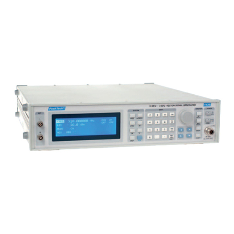
PeakTech 4110 User manual

Safety precautions
To ensure safe operation of the equipment and eliminate the danger of serious injury due to short-circuits
(arcing), the following safety precautions must be observed.
Damages resulting from failure to observe these safety precautions are exempt from any legal claims
whatever.
• Indoor use only
• prior to connection of the equipment to the mains outlet, check that the available mains voltage
corresponds to the voltage setting of the equipment.
• connect the mains plug of the equipment only to a mains outlet with earth connection.
• do not place the equipment on damp or wet surfaces.
• do not subject the equipment to direct sunlight or extreme temperatures.
• do not subject the equipment to extreme humidity or dampness.
• replace a defective fuse only with a fuse of the original rating. Never short-circuit fuse or fuse
housing.
• do not exceed the maximum permissible input ratings.
• conduct measuring works only in dry clothing and in rubber shoes i.e. on isolating mats.
• comply with the warning labels and other info on the equipment.
• check test leads and probes for faulty insulation or bare wires before connection to the equipment.
• disconnect test leads or probe from the measuring circuit before switching modes or functions.
• do not cover the ventilation slots of the cabinet to ensure that the air is able to circulate freely inside.
• do not insert metal objects into the equipment by way of the ventilation slots.
• do not place water-filled containers on the equipment (danger of short-circuit in case of knockover of
the container).
• do not operate the equipment near strong magnetic fields (motors, transformers etc.)
• do not subject the equipment to shocks or strong vibrations.
• keep hot soldering irons or guns away from the equipment.
• allow the equipment to stabilize at room temperature before taking up measurement (important for
exact measurements)
• do not modify the equipment in any way.
• do not place the equipment face-down on any table or work bench to prevent damaging the controls
at the front.
• opening the equipment and service- and repair work must only be performed by qualified service
personnel. Repair work should only be performed in the presence of a second person trained to
administer first aid, if needed.
- Measuring instruments don't belong to children's hands -
Cleaning the cabinet
Prior to cleaning the cabinet, withdraw the mains plug from the power outlet. Clean only with a damp, soft
cloth and a commercially available mild household cleanser. Ensure that no water gets inside the equip-
ent to prevent possible shorts and damage to the equipment.
- 20 -

1. Legend
Frontview
Backside
(1) Frequency LED display (30) Function Select Switch
(2) Attenuation Switch 31) SET/RESET Switch
(3) Channel Select Switch (32) DCΩ/AC (((o)))Switch
(4) Gate Time Switch 33) UP Switch
(5) Data Hold Switch 34) DOWN Switch
(6) Reset Switch (35) Power ON/OFF Switch (DMM)
(7) Period Switch (36) Capacitor Socket
(8) Ratio Switch (37) Range Select Switch
(9) Time Interval Switch (38) 20 Ampere Terminal
(10) Difference Switch 39) Milliampere Terminal
(11) Addition Switch (40) Common Terminal
(12) Totalize Switch (41) Voltage/ΩTerminal
(13) CH A Input Connector (42) DPS LCD Display (3 ½ digits)
(14) CH C Input Connector (43) Voltage Control Knob
(15) CH B Input Connector (44) Ampere Control Knob
(16) VCF Input Connector (45) 5 V/2 A Output Terminal
(17) TTL Output Connector (46) 15 V/1 A Output Terminal
(18) F/G Output Terminal (47) 0-30 V/2 A Output Terminal
(19) Amplitude Control Knob (48) Voltage/Ampere Select Switch
(20) Offset Control Knob 49) Current Limit Indicator
(21) Symmetry Control Knob (50) Power ON/OFF Switch (MAIN)
(22) Sweep Width Control Knob 51) Ground Terminal (Chassis Ground)
(23) Sweep Rate Control Knob 52) Frequency Counter ON/OFF Switch
(24) Frequency Control Dial (53) Function Generator ON/OFF Switch
(25) Function Select Switch (54) 9 V Battery Housing (DMM)
(26) Frequency Range Select Switch (55) RS 232C Serial Interface Port
(27) Output Impedance Select Switch (56) DMM Ampere Fuse (mA Ranges)
(28) Display Option Key (57) DMM Ampere Fuse (20 A Range)
(29) DMM LCD Display (3 3/4 digits) (58) Supply Power Inlet with Power Fuse
- 21 -

2. The PeakTech®4110 Universal System
Please read this operating manual very carefully, prior to operating the instrument.
2.1 Introduction
The PeakTech 4110 Universal System is a compact and powerful performance instrument, capable of meeting
various needs of laboratories, service-workshop, technical training institutes, schools, engineering, and
manufacturing fields, etc.
This instrument is characterized by a wide-range coverage of Function Generator, Universal Counter, DC Power
supply and Digital Multimeter in a single unit.
The PeakTech 4110 incorporates:
1. Function Generator, capable of generating seven (7) forms of wave, i. e. Sine, Square, Triangle,
Skewed Sine, Ramp, Pulse and TTL level square in the seven frequency range sourcing from
1 Hz to 10 MHz.
2. Universal Counter, capable of measuring the frequency ranges from 5 Hz to 1.3 GHz.
3. DC Power Supply, capable of generating the voltage carrying with 5 V/2 A, 15 V/1 A fixed and
0-30 V/0-3 A variable.
4. Digital Multimeter, capable of measuring DC/AC voltage up to 1.000 V DC/750 V AC (true rms), DC/AC
current up to 20 A, resistance up to 40 MΩ, capacitance up to 400 µF, and logic test (C-MOS/TTL). This
section can be hooked into data acquisition system run on Personal computers, printers or pen-plotters etc.,
through a RS-232 C serial interface connector.
2.2 Accessories
This instrument is supplied with the following accessories:
1 pce. Power cable
1 pce. Operation manual
1 pair Black & Red test leads
1 pce. Coaxial cable with BNC connector
1 pce. RS-232 C interface with cable connector
1 pce. 3 ½”-diskette with software for Windows and DOS
3. Safety Precautions
The following safety precautions must be observed at all times during operation, service, and repair of this product.
Failure to comply with these precautions, or with specific warnings elsewhere in this manual violates safety standards
of design, manufacture and intended use of the product. We assume no liability for failure to comply with these
requirements.
• Avoid an extremely hot or cold place for the instrument
• Ground the chassis and cabinet by only using a three-contact AC power cable which must be plugged into an
approved three-contact electrical outlet.
• Do not operate the instrument in wet, damp or explosive areas.
• Keep the instrument away from live circuits, a soldering iron, etc.
• Do not change parts or apply an unauthorized modification to the instrument.
• Make sure that any use of modified fuses or the short circuiting of the fuse-holders shall be prohibited.
• Use only the specified fuses for the instrument, as follows:
* Power line fuse: 1 A/220 V or 240 V
Shape: 6,35 ∅x 31,8
Type: Slow-blow
* DMM ampere fuses: 400 mA AC/DC Ranges: 800 mA/250 V
20 A AC/DC ranges: 20 A/250 V
Shape: 6,35 ∅x 31,8
Type:Fast-blow
- 22 -

• Pay your attention to Warning-signs printed on the instrument
Altitude: max. 2000 m
Temperature: 5° C to 40° C, < 80 % R.H.
• For a proper ventilation, do not cover the cooling plates and don't touch it
• Do not try repair service or adjustment, unless the first aid is available around you.
• To avoid injuries, always disconnect power and discharge circuits by grounding before touching them.
• Safety: EN 61010-1; IEC 1010-1
• EMC: EN 50081-1, EN 50082-1
4. Installation
4.1 Unpacking and inspection
Every care is taken in the choice of packing materials to ensure that your equipment will reach you in perfect
condition.
Unpack the equipment and check for external damage to the case, sockets, keys etc. If damage is found, notify the
carrier and your sales representative immediately.
The standard accessories supplied with the instrument are as described in the Section 1.
4.2 Preparation for Operation
Under no circumstances should users touch any of the front terminals, unless the are first assured that no dangerous
voltage is present.
Power Input
The recess power input plug, power fuse and line voltage indicator are contained in an integral module in the rear
panel.
Power cable
The detachable supply cable, comprising of 3-core PVC cable permanently moulded to a fully-shrouded 3-pin socket,
fits in the power input plug recess and should be fitted fully.
The supply lead should be connected to a grounded AC power receptacle ensuring that the ground lead is
connected, to avoid electrical shock.
Line voltage
The PeakTech 4110 is operative within the line voltage ranges 230 V AC ± 10 %, 50 or 60 Hz, for F/G, F/C and DPS.
The DMM section of the instrument is powered by a single 9 Volt battery (Type NEDA 1604 or 6F22). The battery
annunciator appears on the LCD display, when the battery voltage drops to certain limits. Continued operation with a
flat battery will lead abnormal readings.
Bench Mounting
This instrument is fitted with four rubber feet. It is intended to stand flat on a bench, located at least 30 cm of free
space at the rear.
In addition, 2 plastic tilt-stand are provided next to the front rubber feet, to facilitate the viewing angle of the
instrument from the bench level.
5. Operating the PeakTech 4110
Prior to operating this instrument, it is important that it has been correctly installed as detailed in the Section 4.
The operating instructions are devided into four major groups; Universal Counter (U/C). Function Generator (F/G),
DC Power Supply (DPS) and Digital Multimeter (DMM). - 23 -
The user should refer to the operation manual to protect the instrument against damage.
Dangerous voltage exists.
Ground (Earth terminal)

Throughout these sections, warnings identify potentially dangerous procedures. Instructions contained therein must
be observed.
5.1 Operating the universal counter
Check the line voltage and fuse ratings before connecting to the power outlet. Be sure to turn on U/C power switch
located on the rear panel. For stabilizing the counter, warm-up time of 20 minutes is required, before commencing
measurements.
5.1.1 Specification
Input frequency measurement
Measuring range
Channel A and B 5 Hz to 100 MHz LSD display depending on Gate Time and Input Signal
At least 7 Digits displayed per second of Gate Time
Channel C 100 MHz to 1.3 GHz
Input Voltage
Channel A and B 70 mV RMS Sinewave or 100 mVp
Channel C 35 mV RMS Sinewave or 70 mVp
Maximum Input Voltage
Channel A, B + C 3 V
Input Impdance
Channel A, B 1 MΩ
Channel C 50 Ω
Attenuator
Channel A only 1 or 1/10 (-20 dB)
Time Base
Channel A, B and C Switch selectable
Resolution
Channel A, B and C
100 MHz or more 10 Hz/0.1 s, 1 Hz/1 s, 0.1 Hz/10 s
100 MHz or less 6 digit/0.1 s
7 digit/1 s
8 digit/10 s
Period Measurements
Channel A and B
Range 0.1 Sec to 10 Sec
LSD Display 1 µSec to 0.1 Psec
Depending on Gate Time and Input signal at least 7 digits displayed per second of Gate
time.
Channel C
Range 0.1 sec to 10 sec.
LSD display Least display limited by Display method 0.1 Psec.
Totalize
Totalize A or B
Manual Range 0 to 9, 99, 999
Manual reset possible
Ratio A/B measurements
Range 5 Hz to 100 MHz both channels
LSD display 2.5 x period x Ratio
Gate Time
Difference A-B
Range 5 Hz to 100 MHz both channels
LSD display 100 Hz to 100 µHz depending on Gate Time, Input signal and display method
Addition A + B
Range 5 Hz to 100 MHz both channels
LSD Display 100 Hz to 10 nHz depending on Gate Time and Input Signal
- 24 -

Time interval A ⇒B
Range 100 nSec to 10 Sec
LSD Display 100 nSec
Average 1, 10, 100 Intervals Averaged
Overflow Indication The OVER LED indicator flashes, when an input exceeds, only under the LOW range set
at 10 S gate time
Operating temperature 10° C to 40° C
Storage temperature -10°C to 50° C
Line Voltage Range 230 V AC at 50/60 Hz ± 10 % max., selectable
Power Consumption 2 W max.
Coaxial cable
(with BNC connector) RG-58 C/U, Impedance 50 Ω, with one (1) meter in length
5.1.2 Start-Up
• Check conductors of the A, B and C channels in good condition
• Connect the AC power cable to the recess power receptacle and plug it into three-contact electrical outlet
• Turn on the Power switch of DPS
• Turn on the Power switch of U/C located on the rear panel. In this case, all segments, PASS-ALL and UC-1300
shall be displayed as a self test.
• Set the display Option key (28) at U/C position.
• Set the Gate time switch (4) at 1 S position.
• Set the Channel Select Switch (3) at Channel A position.
• Set the Data-Hold Switch and the Attenuation Switch at the pushed-out position. Now, "GATE" "0.0000000"
"MHz" is lit up at frequency LED display.
5.1.3 Features
Channel Select Switch (3)
The Channels A and B will cover your measurement of the frequency from 5 Hz up to 100 MHz with auto range. The
Channel C will cover your measurement of the frequency from 100 MHz up to 1.3 GHz.
Gate Time Switch (4)
For a better resolution in your measurement, your selection for a proper gate time is advisable. The following table
will help you refer to the optional frequency resolution.
Frequency Resolution Table
Gate Time 100 mS 1 S 10 S
Low Range 10 Hz 1 Hz 0,1 Hz
High Range 100 Hz 10 Hz 1 Hz
Data-Hold Switch (5)
Upon activation of this mode, a read-out on the LED display will be captured and remained even after disconnecting
the test connector from a measuring point.
Attenuation Switch (2)
If input signal is greater than 700 mV, set the Attenuation Switch at the pushed-in position with connecting the input
signal to channel A only.
The triggering sensitivity of the input signal will be decrease by 1/10 (-20 dB) and reduce errors.
Reset Switch (6)
If you want to return to the normal frequency mode from the arithmetic modes, set FREQ switch at the pushed-in
position.
5.1.4 Mesuring the output frequency generated by F/G
If you want to measure the output frequency being measured by the function generator, set the display option key
(28) at F/G position. - 25 -

Because the maximum output frequency of F/G is 10 MHz, the range select channel should be set at CH-A which can
read the frequency ranging from 5 Hz to 100 MHz.
Under activation of this mode, the universal counter will not measure any input frequency injected from the frequency
input connector.
5.1.5 How to using the arithmetic modes
Period Measurement Procedure:
Perform Period measurement as follows:
1. Press the Power to ON position.
2. Set the channel selector to the desired channel prior to pressing the PERIOD switch to select the period
mode of operation.
3. Connect the input signal to the front-panel BNC connector.
4. Read the period time on display.
Ratio A/B Measurement Procedure:
This measurement shows the value of the channel A signal divided by the Channel B.
1. Press the Power switch to ON position.
2. Press A/B switch
3. Connect the input signal to the front-panel BNC connector CH-A and CH-B
4. Read the value on display.
Time Interval A ⇒B Measurement Procedure:
This measurement counts the scaled reference frequency for a period whose start is determined by the CH-A input
signal and whose stop is determined by the CH-B signal.
1. Press the Power to ON position.
2. Press A ⇒B Switch
3. Connect the input signal to the front-panel BNC connector CH-A and CH-B.
4. Read the value on the display.
Difference A-B Measurement Procedure
This measurement counts the subtraction of the scaled input pulses occured between CH A signal and CH B signal.
Perform A-B measurement as follow:
1. Press the Power switch to ON position.
2. Press A-B switch.
3. Connect the input signal to the front-panel BNC connector CH A and CH B.
4. Read the value on the display.
Addition A + B Measurement Procedure
This measurement counts the addition of the scaled input pulse occured between CH A signal and CH B signal.
Perform A + B measurements as follows:
1. Press the power switch to ON position.
2. Press A+B switch
3. Connect the input signal to the front-panel BNC connector CH A and CH B.
4. Read the value on the display.
Totalize Measurement Procedure
Perform totalize measurement as follows:
1. Press the Power switch to ON position.
- 26 -

2. Press TOTAL switch to select the totalize mode of operation and to initialize the counter.
3. Connect the input signal to the front-panel BNC connector CH A or CH B.
4. If input signal is greater than 700 mV, set the Attenuation switch at the pushed-in position with connecting
the input signal to Channel A only.
The triggering sensitivity of the input signal will be decreased by 1/10 (-20 dB) and reduce errors.
5. Read the accumulated value on the display after depressing the HOLD switch.
5.2 Operating the Function Generator (F/G)
Check the line voltage and fuse ratings before connecting to the power outlet. Be sure to turn on F/G power switch
located on the rear panel. For stabilizing the system, warm-up time of 30 minutes is required before commencing
operation.
5.2.1 Specification
Wave Forms Sine, Square, Triangle, Skewed Sine, Ramp, Pulse, TTL Level Square
Frequency 1 Hz to 10 MHz in 7 ranges
VCF Voltage Level 0 to 10 V DC (Max. input voltage: ± 15 V)
Output Impedance 50 Ω± 10 %, 600 Ω± 10 % selectable
Output Amplitude 2 Vpp to 20 Vpp at open load
1V
pp to 10 Vpp at 50 Ωload
Attenuator -20 dB
Frequency Variable Range 20 : 1 or more
Symmetry Variable range 3 : 1 or more
Offset Variable Range Max. ± 10 V DC
Sine Wave
- distortion Less than 1 % (at 1 kHz)
- flatness ± 0.3 dB
Square wave
- symmetry Less than ± 3 % (at 1 kHz)
- Rise and fall time Less than 150 ns (at 1 kHz)
Triangle wave
- linearity Less than 1 % (up to 100 kHz)
Less than 5 % (100 kHz to 2 MHz)
TTL output
- Rise and fall time Less than 30 ns (at 1 kHz)
- Output level More than 3 V
Frequency sweep
- sweep time 20 ms to 2 s
- internal sweep mode Linear
logarithmic
- sweep width More than 100 : 1
- External sweep by
means of VCF input
5.2.2 Start up
• Check conductors of the terminals in good condition without shorted
• Connect the AC power cable to the recess power receptacle located on the rear panel and plug it into the three-
contact electrical outlet.
• Turn on the power switch (50) of the DPS
• Turn on the power switch of the F/G located on the rear panel.
- 27 -

• Set all the variable controls, as follows:
Variable Controls Setting Position
Function Select Switch (25) Sinewave
Freq. Range Select Switch (26) X 1 k
Freq. Control Dial (24) 1.0
Amplitude Control knob (19) Switch off (push-in position)
Offset Control Knob (20) Switch off (push-in position)
Symmetry Control Knob (21) Switch off (push-in position)
Sweep Width Control Knob (22) Switch off (push-in position)
Sweep rate Control knob (23) Switch off (push-in position)
• Match the output impedance between the F/G output and the unit under test by switching the impedance output
select switch (27).
• In case that you want to measure the frequency under process, please refer to the section 5.1.4 for further
information.
5.2.3 Wave Forms
The basic ramp signal has been generated by the OP Amp. Based on this basic signal, the squarewave has been
formed by the line receiver IC. And, the sinewave has been formed by the quardruple TR IC.
The output wave forms and phase relationship are as follows.
Note: Under activation of the 600 Ωimpedance mode (27), the output wave forms can be normal up to 100 kHz
range.
5.2.4 Frequency ranges
The PeakTech 4110 can supply the frequency in the 7 ranges, as shown on the following table
Frequency Range assigned to each select switch
Select Switch Assigned Range Maximum Output
X10 1 Hz – 10 Hz 10 Hz
X100 10 Hz – 100 Hz 100 Hz
X 1 k 100 Hz – 1 kHz 1 kHz
X 10 k 1 kHz – 10 kHz 10 kHz
X 100 k 10 kHz – 100 kHz 100 kHz
X 1 M 100 kHz – 1 MHz 1 MHz
X 10 M 1 MHz – 10 MHz 10 MHz
Note:
The output frequency can be read by multiflying figures optioned by the frequency control dial (24), and the frequency
Range select switch (26).
Ex. 1 kHz = 0.1 (at the dial 24) x 1 K (at the S/W 26)
- 28 -

5.2.5 Features
Voltage Controlled Frequency
Output frequency can be varied with an external input from the VCF input Terminal (16).
For 0 ~ 10 V DC VCF input voltage, the frequency is changed by 1:2, depending upon activation of the frequency
range select switch (26). To operate the VCF function, turn the frequency control knob (24), fully CCW, and connect
the external voltage to the VCF input terminal.
Amplitude Control
The maximum amplitude of output voltage is more than 20 V under the open load, but it is reduced by half (50 %)
under the 50 Ωload or 600 Ωload. The amplitude output voltage can be varied continuously with operating the
Amplitude control knob (19), in the range of -20 dB. If the Amplitude Control Knob is pulled out, the output signal is
set to the -20 dB fixed.
OFF-SET Control
The DC level of output signal can be varied continuously with operating the OFF-SET control knob (20) in the range
of ± 10 V. To adjust the DC level, pull out the OFF-SET control knob then, turn slowly CW (positive volt) or CCW
(negative volt). If the OFF-SET control knob is pushed in, there is no DC level, but only AC voltage exists in the
output signal.
Symmetry Control
The duty cycle of output signal can be varied continuously with the symmetry control knob (21) in the range of 1:3 or
3:1. To adjust the symmetry of the waveforms, pull out the symmetry control knob, then turn it slowly to the CCW
direction. The following table shows such variations under this mode.
Note: After setting the symmetry control knob (21), the output frequency will decrease and the operator should re-
adjust the frequency.
Sweep Control
To enable the internal frequency to sweep, pull out the sweep width control knob (22). The width of the frequency
sweep can be varied continuously in the range of 100 : 1. To maximize the sweep width, set the frequency control
dial (24) fully to the CCW direction, and turn the sweep width control knob fully to CW.
To adjust the rate of frequency sweep, turn the sweep rate control knob slowly CW or CCW or linear frequency
sweep. Logarithmic frequency sweep mode is operative with by pulling the sweep rate control knob (23).
TTL Output
The TTL level signal output is available at the TTL output terminal (17). The TTL output can drive 30 unit loads in the
HIGH state and 20 unit loads in the LOW state. One unit load in the HIGH state is defined as 40 µA and 1.6 mA in the
LOW state.
- 29 -

Output Impedance
Output impedance of the function generator can be changed with the 50 Ωor the 600 Ωby pressing or releasing the
output impedance select switch (27).
Under activation of the 600 Ωmode, the output frequency in normal waveform is available in the range of 1 kHz to
100 kHz.
5.3 Operating the DC power supply
Check the line voltage and fuse ratings before connecting input power. Do not short "+" and "-" output terminals.
Avoid a heavy shock to this instrument. For continued protection against damage, do not connect loads below 2.5 Ω
to the Terminal (46) and below 15 Ωto the Terminal (47).
5.3.1 Specification
Terminal l (47) Terminal (45) Terminal (46)
Output voltage 0 – 30 V 5 V fixed 15 V fixed
Output current 0 – 3 A 2 A 1 A
Ripple 1 mV max. 2 mV max. 2 mV max.
Load Regulation 0,1 % + 5 mV 0,1 % + 70 mV 0,1 % + 35 mV
Line Regulation 0,1 % + 5 mV 0,1 % + 30 mV 0,1 % + 30 mV
Output current
(maximum) 3 A
(current limit) 2.2 A
(fold back) 1.2 A
(fold back)
Display with back-lit LCD 3 ½-digit
V/A selectable Turn-on
LED Turn-on
LED
5.3.2 Start-Up
• Be sure to disconnect any load from the output terminals, before energizing the instrument
• Turn the Ampere Control Knob (44) fully CW to ensure that the output current reaches a maximum output.
• Connect the AC power cable to the recess power receptacle, located on the rear panel, and plug it into the three-
contact electrical outlet.
• Press the Power ON/OFF Switch (50) to turn on
• The LED indicators "5 V 2 A" and "15 V 1 A" will light.
• In order to use the variable voltage or current, you can choose the Voltage/Ampere Select switch (48). While
observing the displayed figures on the LCD (42), set your voltage in need, by turning the voltage control knob
(43).
• In need of limiting the current for protection your device under test, set your limit current by the current control
knob (44). During operation of the DPS, an excessive current over your setting current will lead the voltage to
drop down and the current limit indicator (49) will light.
Note:
This DC power supply has the output terminals isolated from the grounding terminal (chassis ground). However, the
0-30 V/0-3 A output terminal has been connected by the short-bar between the ground terminal (51) and the (-)
output connector of the terminal at the factory.
5.4 Operating the Digital-Multimeter
The Digital Multimeter is powered by a single 9 volt battery, and fully isolated from the U/C, F/G, DPS and the
chassis.
5.4.1 Precautions
• To prevent electric shock hazard and/or damage to the meter, do not measure voltages exceeding 1000 V DC or
750 V AC.
• To avoid damage to the meter, disconnect test leads from test points before changing the function/range.
• To avoid electrical shock, be careful when working above 60 V DC or 25 V AC. Such voltages pose a shock
hazard.
• Do not apply voltage between the 20 A or mA and COM terminals. This warning is to assure protection against
injury and/or damage to the meter and the user.
- 30 -

• To avoid damage to the meter and/or injury observe the input limits as stated hereunder.
Input Limits
Function Terminal Input Limits
V DC V/Ω+ COM 1000 V DC
V AC V/Ω+ COM 750 V AC
ΩV/Ω+ COM 250 V DC/AC
mA DC/AC mA + COM 400 mA DC/AC
20 A DC/AC 20 A + COM 20 A DC/AC
Logic V/Ω+ COM 250 V DC/AC
• The common input of the multimeter must never be connected to circuitry which is more than 500 V above
ground potential. Failure to observe this precaution may result in injury to the user, damage to the meter and
connected computer equipment.
• To avoid electrical shock hazard, do not touch test leads, tips or the circuit under measurement while power is
turned on.
• Ensure the test leads are in good condition.
5.4.2 Specification
LCD display 3 ¾ digits w/dual-Display, Analog Bargraph and Back Lit
Function/Range Selection Push-button and rotary switch
Relative OFFSET 3999 counts
Input impedance 10 MΩ
AC/DC max. input current 20 A (15 minutes max.)
Reading time 10 reading per second
Operating temperature 0°C to 40° C
Storage temperature -10° C to 50° C
Temp. for guaranteed Accuracy 23° C ± 5° C
Battery Type NEDA 1604 9 V or 6F22 9 V
- 31 -

Function Range Accuracy Resolution
400 mV
4 V
40 V
400 V
± 0,3 % of rdg. + 1 dgt.
100 µV
1 mV
10 mV
100 mV
DC Voltage
1000 V ± 0,5 % of rdg. + 1 dgt. 1 V
400 mV
4 V
40 V
400 V
± 2,5 % of rdg. + 5 dgt.
100 µV
1 mV
10 mV
100 mV
AC Voltage (True rms)
750 V ± 1,0 % of rdg. + 3 dgt. 1 V
40 mA
400 mA ± 0,8 % of rdg. + 1 dgt. 10 µA
100 µA
DC Current
20 A ± 1,5 % of rdg. + 5 dgt. 10 mA
40 mA
400 mA ± 2,0 % of rdg. + 3 dgt. 10 µA
100 µA
AC Current (True rms)
20 A ± 2,0 % of rdg. + 5 dgt. 10 mA
400 Ω
4 kΩ
40 kΩ
400 kΩ
4 MΩ
± 0,5 % of rdg. + 1 dgt.
1,0 Ω
1 Ω
10 Ω
100 Ω
1 kΩ
Resistance
40 MΩ± 1,0 % of rdg. + 2 dgt. 10 kΩ
4 nF
40 nF
400 nF
± 2,0 % of rdg. + 3 dgt. 1 pF
10 pF
100 pF
Capacitance
4 µF
40 µF
400 µF
± 3,0 % of rdg. + 5 dgt. 1 µF
10 µF
100µF
40 mH ± 3,0 % of rdg. + 20 dgt. 10 µH
Inductance 400 mH ± 3,0 % of rdg. + 10 dgt. 100 µH
Features
• Computer Interface & Software - let you interface the meter with your PC-compatible computer so you can log
measurements.
• Analog Bargraph Display - indicates the magnitude of the input compared to the full-scale value of the
measurement range.
• Dual-Display - allows the meter to show two primary + secondary readings simultaneously on the LCD. For the
measurement of AC Volt and Logic, "d" is displayed at the front of secondary display to measure and to readout
two different types of measurement at the same time.
Input Range Selection Main Display Secondary display
AC Voltage AC Voltage dB(m)
Logic HI/LO DC Voltage
• Overload and Transient Protection - helps protect the meter from accidental overload on most ranges. "OL" is
displayed with flashing the bar-graph, when an input is too excess to display.
• Back-Lit display - affords you of a more flexibility in your working area when turn the power to on. Back-Lit is
powered by a voltage supplied from Power supply (DPS).
• Auto-Hold - freezes a reading automatically recorded 3 seconds ago, when last reading is completed. For the
measurement of DC Volt, Current, Diode, Capacitance "A" is displayed at the front of secondary display. When
this feature is turned on, the secondary display shows the reading taken 4 – 5 seconds earlier.
• Min./Max/Data-Hold - let you keep a readings of minimum, maximum and captured value on the on the
sub-display, while showing the present readings on the main-display.
• Range-Hold - sets the meter from auto-range to manual-range mode except capacitance position. In the manual-
range mode, each you press UP DOWN keys, the range and the input range annunciator increment and/or
decrements, and a new value is displayed.
• Relative Offset - displays the difference between the stored value and subsequent readings. To set the reference
value, follow these steps: - 32 -

1.) Set the function mode at REL mode.
2.) Store the polarity, values and range of the reference value you desire by pressing the UP DOWN keys
and SET/RESET key by turns.
3.) Press SET/RESET key for final setting. Then your meter will be set in the manual-range automatically. In
this mode, the total range of relative offset is 3999 counts.
• Memory & Memory Recall - Stores and recall a measured reading up to five values.
• Comparision - enables to do the HIGH LOW test of subsequent readings by comparing a reading with both the
stored the highest reference value and the stored lowest reference value. To set the reference values of Min and
Max, see the steps of REL 2, 3. On the sub-display. LO sign for reading less than the lowest reference value, HI
sign for reading more than the highest reference value and PASS for middle reading.
• Logic test Function - checks logic levels without extra logic probes.
• EXT - your meter can measure and readout two different types of measurement at the same time. To set EXT
feature, repeatedly press FUNCTION until EXT appears at the top of the display.
The meter displays the following extra measurements:
Input Range Selection Main Display Secondary display
AC Voltage AC Voltage Frequency
AC Current AC Current Frequency
DC V/DC A/CAP/hFE/OHM/
Inductance DC V/DC A/CAP/hFE/OHM/
Inductance
Auto Hold
5.4.4 Making Measurements
Understanding Phantom Readings
In some DC and AC voltage ranges, when the probes are not connected to any circuit, the display might show a
"phantom" reading. This is normal. The meter's high input sensitivity produces a wandering effect. When you connect
the probes to a circuit, accurate readings appear.
Measuring High-Voltage circuits
When you use the meter to check a high voltage circuit, do not try to position both probes at once. Instead, clamp
one probe to the neutral or ground lead of the circuit (usually a bare, green, or white of the in AC wiring circuits) using
insulated slip-on alligator clips. Then probe for voltages with the other probe. This helps prevent you from accidentally
touching a hot wire because you need to concentrate on only one test probe.
WARNING! Never clamp onto a hot wire (usually red, black or blue in AC wiring circuits). If you clamp onto a hot wire
and touch the other probe, you could receive a shock.
AC/DC Voltage Measurement
Warning: Do not try to measure a voltage greater than 1000 Volts DC or 750 Volts AC. You might damage
your meter and expose yourself to a severe shock hazard.
Note: All the figures on the display blink when more than the maximum voltage (DC 1000/AC 750 Volts) is supplied.
If this happens, DISCONNECT THE PROBES IMMEDIATELY.
Follow these steps to measure AC/DC Voltage:
1. Rotate the range selector to the desired V AC or DC position.
2. Press the DCΩ/AC (((o)))button to toggle between DC and AC voltage.
3. Plug the black probe into the meter's COM terminal and the red probe into the meter's V/Ωterminal.
4. Connect the meter in parallel with the load or circuit.
Notes:
• If polarity is negative, - appears on the left of display.
• For the most accurate measurement, select the lowest voltage range possible without getting an overload
reading.
• Each of the AC/DC voltage ranges presents an input impedance of approximately 10 MΩin parallel with
less than 100 pF. AC voltage is ac-coupled to the 10 MΩinput.
Caution: Never try to measure an AC voltage that is ringing on a DC voltage level where the peak AC voltage
exceeds 1000 V with respect to earth ground.
- 33 -

Measuring AC/DC current
WARNING: YOU MAY DAMAGE THE METER OR BE INJURED IF THE FUSE BLOWS WHILE CURRENT IS BEING MEASURED IN A
CIRCUIT WHICH EXHIBITS AN OPEN CIRCUIT VOLTAGE GREATER THAN 250 V. THE 20 A TERMINAL IS FUSED. A SEVERE FIRE
HAZARD AND SHORT CIRCUIT DANGER EXISTS IF YOU APPLY A VOLTAGE WITH HIGH CURRENT CAPABILITY TO THIS TERMINAL. THE
METER CAN BE DESTROYED UNDER SUCH CONDITIONS.
Follow these steps to measure current:
1. Rotate the range selector to the desired Ampere position.
2. Press DCΩ/AC (((o)))button to toggle between DC and AC Ampere.
3. Plug the black probe into your meter's COM terminal and the red probe into your meter's mA or 20 A
terminal.
4. Remove power from the circuit under test and then break the circuit at the appropriate point.
5. Connect the meter in series with the load or circuit under test.
Notes:
• If you do not know approximately what the current is, connect the circuit to 20 A input terminal first to see if you
have a safe level for the mA input terminal. Use the mA input terminal for current up to 400 mA.
• When measuring current, the meter's internal shunt resistors develop a voltage across the meter's terminals
called "burden voltage". This voltage drop is very low in your meter, but, it may affect precision circuits or
measurements.
• If you set the meter for DC current, - appears or disappears to indicate the polarity of the measured current.
Measuring Capacitance
Follow these steps to measure normal capacitance:
1. Discharge each capacitor before testing by shorting its leads together. Use caution when handling some
capacitors, as they can be charged with considerable electricity.
Caution: If you attempt to measure the capacitance of a charged capacitor, you might damage your meter.
2. Rotate the range selector to the desired CAP range.
3. Insert the discharged capacitor into the CAP + and - clips connectors. Your meter displays the
capacitance value.
Note: for polarized capacitors, be sure to insert the negative leads in the - clip.
Measuring Resistance
WARNING!
NEVER CONNECT THE TEST PROBES TO A SOURCE OF VOLTAGE WHEN YOU HAVE SELECTED THE OHMS FUNCTION AND PLUGGED
THE PROBES INTO THE V/ΩTERINAL. BE SURE THAT THE CIRCUIT UNDER TEST HAS ALL POWER REMOVED AND THAT ANY
ASSOCIATED CAPACITORS ARE FULLY DISCHARGED BEFORE YOU MAKE A RESISTANCE MEASUREMENT.
Follow these steps to measure resistance:
1. Rotate the function selector to the (((o)))Ωrange.
2. Press the DC Ω/AC (((o)))button to toggle between resistance and continuity.
3. Connect the probes to the device you want to measure.
Notes:
• If the measured resistance value exceeds the maximum value of the range selected. "OL" displays to indicate
overload and the bar graph flashes.
• The resistance in the test leads can diminish accuracy on the lowest range. The error is usually 1 to 0.2 ohms for
standard pair of test leads. To determine the error, short the test leads together and read the resistance of the
leads.
• For resistance of approximately 1 MΩand above, the display might take a few seconds to stabilize. This is
normal for high resistance readings.
- 34 -

Checking Continuity
Continuity testing verifies that circuit connections are intact. To perform audible continuity tests, set the rotary switch
to (((o)))Ωpress the DC/AC (((o)))button to toggle between resistance and continuity, and connect the meter to your
circuit.
Warning: Never perform a continuity measurement on a circuit that has power connected.
Note: The buzzer sounds if the measured resistance is below 30 ohms.
Logic Test
The logic function lets you easily check the digital circuits to determine the logic state of different parts of the circuit.
Rather than display an absolute voltage, this function displays Hi, LO, or ---- indicated logic high, low, or undeter-
mined respectively.
Follow these steps to perform logic test:
1. Rotate the function selector to the LOGIC range.
2. Plug the back probe into your meter's COM terminal and the red probe into your meter's V/Ωterminal.
3. Connect the black probe to the ground point (GND) of the test circuit and the red probe to the supplying
voltage point (V+). While keeping the test probes firmly connected to each point, press SET/RESET key.
4. While keeping a connection between the black probe and the circuit's GND point, move the red probe to
the other desired points. The meter immediately displays one of the 3 modes, as follows:
- If value exceeds 70 % of the stored (V+) value, Hi (HIGH) appears
- If value falls below 30 % of the stored (V+) value, LO (LOW) appears
- If value is between 30 % and 70 %, the segment ---- appears.
Notes:
• In this mode, the data-hold and Max/Min-Hold functions do not work.
• The supplying voltage above 3 V for setting the reference value and from 0 V up to 39.99 V is limited for testing a
logic.
• After performing logic test, you must press set/reset button before rotating the range selector to another range.
Measuring Inductance
Your meter can measure coils up to 400 mH. Follow these steps to measure inductance.
1. Rotate the function selector switch to 400 mH
2. Insert the discharged coil into the outermost connections and read the display.
Notes
• When the input is not connected, i. e. at an open circuit, OL is displayed to indicate an overrange condition.
• Please refer to a test condition as below. If OL is not displayed at open status, press DCΩ/AC (((o))) so your meter
displays OL
Refer
Refer to reading error as specified at special characteristics.
- 35 -
Test Condition
Frequency = 550 Hz (Square Wave)
Internal Series Resistance Error
400 mH RS= 4.7 kΩ
Internal Resistance Error (%)
R(s) 400 mH
Ohm Error (%)
0,1 -0.1
0,2 -0.1
0,5 -0.1
1 -0.1
2 -0.1
5 -0.1
10 -0.2
20 -0.4
50 -1
100 -2
200 -4
500 -10
1000 -17

6. Using the Meter with a Computer
We have included two programs to log and display data collected with your meter. The MS-DOS program is called
METEX, and is in the GRAPHIC subdirectory on the supplied diskette. The windows program is called SCOPEVIEW,
and is in the Scope directory on the supplied software.
I. Using the DOS software
Follow these steps to install and run the MS DOS software.
Note: The following steps assume a basic knowledge of MS-DOS commands, and also assume you have a hard
disk. Refer to your computer's User's guide for information about MS-DOS commands. This software requires a VGA
monitor.
1. Insert the supplied software in your computer's drive.
2. Creat a directory on your hard disk for the software.
For example, to make a directory called METER for the software, type:
cd\<ENTER>
md METER <ENTER>
3. Make the directory you created in the current directory
For example, if the directory is METER, type:
cd\METER<ENTER>
4. Copy the files from the GRAPHIC subdirectory on the floppy drive to your hard disk. For example, type:
copy a:\GRAPHIC C:
5. To run the program, type METEX<ENTER>. Follow the on-screen help for specific operating
instructions
Notes:
If you do not have a hard disk, you can still run the program from the supplied floppy diskette. Change to the
GRAPHIC subdirectory on the diskette, and type METEX <ENTER>.
* To stop the program or to escape from a drive I/0 error, press <CRTL+BREAK>.
* Selects METER type M3850/3830 on SETUP menu.
II. Using the Windows Software
Follow these steps assume a basic knowledge of Microsoft Windows. Refer to your computer's Windows User's
Guide for information about using Windows. This software requires Microsoft Window, version 3.1 and a VGA or EGA
display.
1. Start your computer and run windows.
2. Insert the supplied diskette in your computer's drive.
3. From the Windows Program Manager, pull down the FILE menu and select the RUN option.
4. At the prompt, type:
a:\scope\setup<ENTER> (If you placed the disk in Drive A)
b:\scope\setup<ENTER> (If you placed the disk in Drive B)
5. Follow the on-screen prompt to complete installation.
6. To run the program, double-click the SCOPEVIEW icon.
Follow the on-screen help for specific operating instructions.
Also refer to the README file in the diskette's SCOPE subdirectory for operation hints.
Data Format
The data format consists of a frame of 14 bytes. The frames are set as follows:
BYTE) 1 2 3 4 5 6 7 8 9 A B C D E
Ex.1) D C - 3 . 9 9 9 V CR
Ex.2) 3 . 9 9 9 M o h m CR
Communication parameters
Transmission rate: 1200 baud
Character coding: 7-bit ASCII
Parity: None
Stop Bits: 2
- 36 -

All rights, also for translation, reprinting and copy of this manual or parts are reserved. Reproductions of all kinds (photocopy,
microfilm or other) only by written permission of the publisher. This manual is according the latest technical knowing. Technical
changings which are in the interest of progress reserved.
©HGL
Händler/Distributor
- 37 -
Table of contents
Other PeakTech Laboratory Equipment manuals