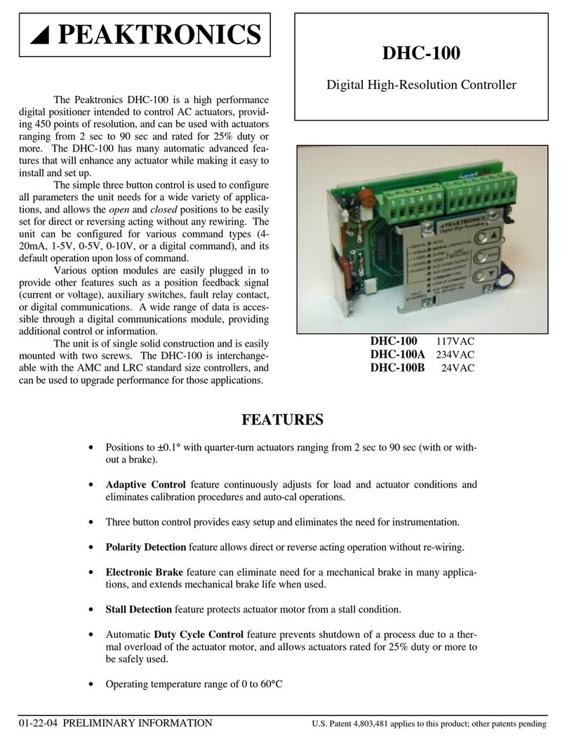
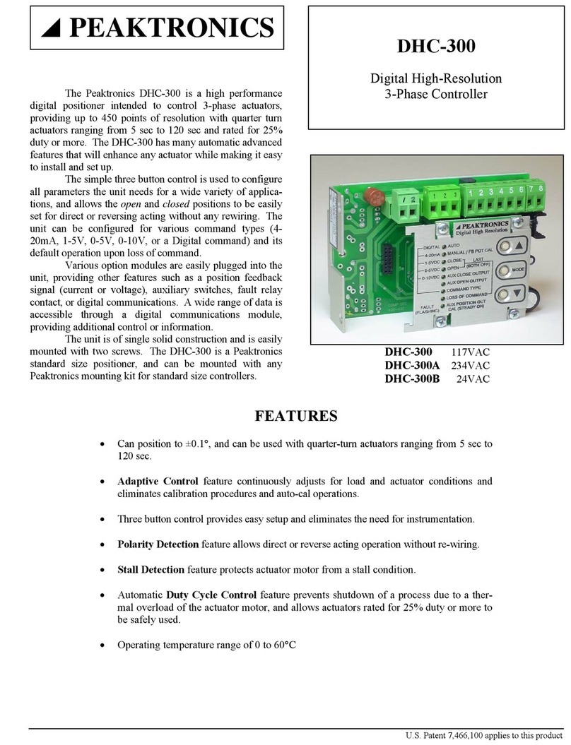
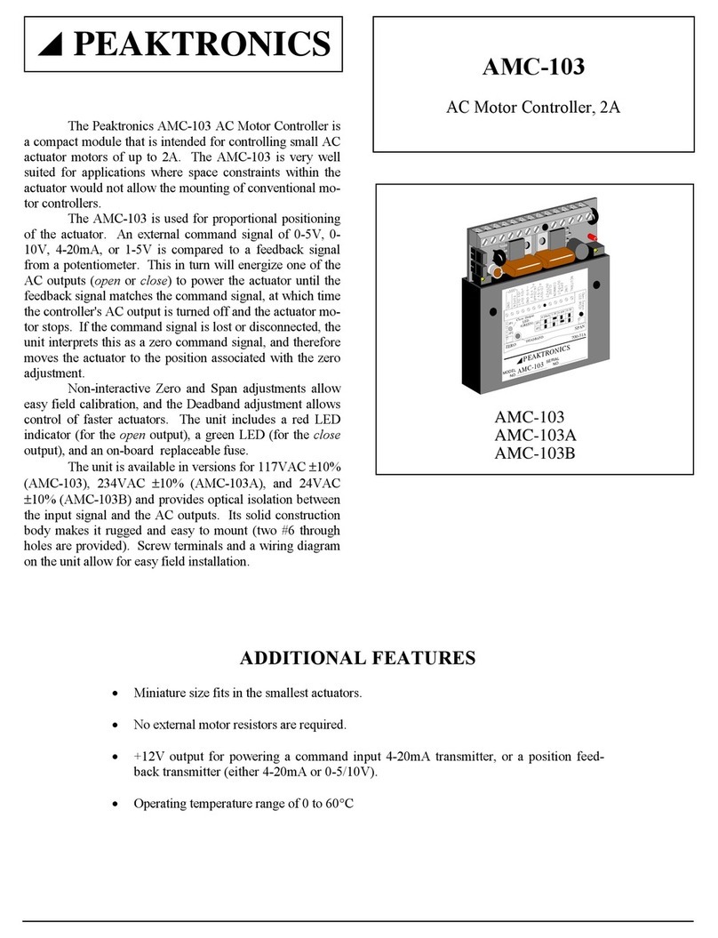
Peaktronics DHC-301 User manual

DHC-301
page
1 of 4
Quick Cal & Troubleshooting Guide
www.peaktronics.com
PEAKTRONICS, Inc.
1363 Anderson Clawson, MI 48017 Phone (248) 542-5640 FAX (248) 542-5643
800-210A
Quick Calibration Procedure
General
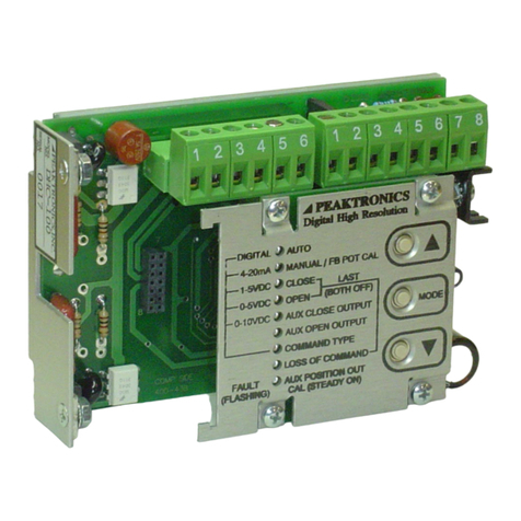
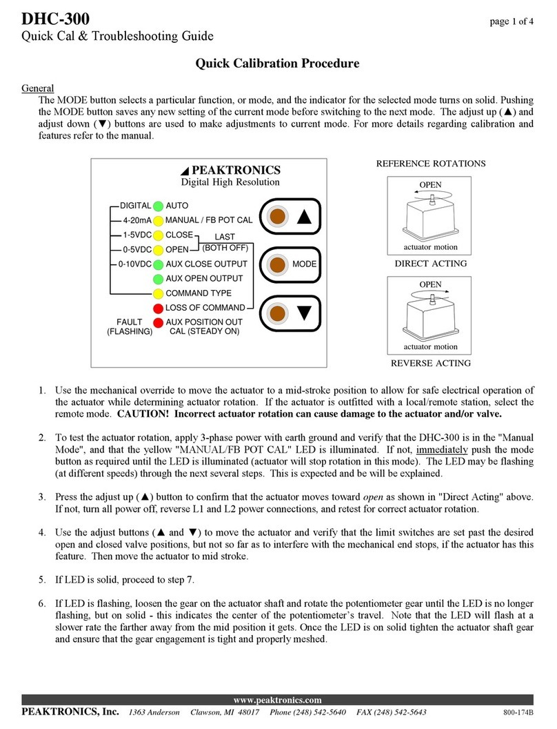
The MODE button selects a particular function, or mode, and the indicator for the selected mode turns on solid. Pushing
the MODE button saves any new setting of the current mode before switching to the next mode. The adjust up (▲) and
adjust down (▼) buttons are used to make adjustments to current mode. For more details regarding calibration and fea-
tures refer to the manual.
AUTO
MANUAL / FB POT CAL
CLOSE
OPEN
AUX CLOSE OUTPUT
AUX OPEN OUTPUT
COMMAND TYPE
LOSS OF COMMAND
DIGITAL
4-20mA
1-5VDC
0-5VDC
0-10VDC
LAST
MODE
Digital High Resolution
(BOTH OFF)
PEAKTRONICS
POSITION OUT CAL
FAULT
2-10VDC
OPEN
actuator motion
OPEN
actuator motion
REVERSE ACTING
REFERENCE ROTATIONS
DIRECT ACTING
1. Use the mechanical override to move the actuator to a mid-stroke position to allow for safe electrical operation of
the actuator while determining actuator rotation. If the actuator is outfitted with a local/remote station, select the
remote mode. CAUTION! Incorrect actuator rotation can cause damage to the actuator and/or valve.
2. To test the actuator rotation, apply 3-phase power with earth ground and verify that the DHC-301 is in the "Manual
Mode", and that the yellow "MANUAL/FB POT CAL" LED is illuminated. If not, immediately push the mode
button as required until the LED is illuminated (actuator will stop rotation in this mode). The LED may be flashing
(at different speeds) through the next several steps. This is expected and be will be explained.
3. Press the adjust up (▲) button to confirm that the actuator moves toward open as shown in "Direct Acting" above.
If not, turn all power off, reverse L1 and L2 power connections, and retest for correct actuator rotation.
4. Use the adjust buttons (▲and ▼) to move the actuator and verify that the limit switches are set past the desired
open and closed positions, but not so far as to interfere with the mechanical end stops, if the actuator has this fea-
ture. Then move the actuator to mid stroke.
5. If LED is solid, proceed to step 7.
6. If LED is flashing, loosen the gear on the actuator shaft and rotate the potentiometer gear until the LED is no longer
flashing, but on solid - this indicates the center of the potentiometer’s travel. Note that the LED will flash at a
slower rate the farther away from the mid position it gets. Once the LED is on solid tighten the actuator shaft gear
and ensure that the gear engagement is tight and properly meshed.

DHC-301
page
2 of 4
Quick Cal & Troubleshooting Guide
www.peaktronics.com
PEAKTRONICS, Inc.
1363 Anderson Clawson, MI 48017 Phone (248) 542-5640 FAX (248) 542-5643
800-210A
7. Push the MODE button until the “CLOSE” LED is lit solid. Use the adjust down (▼) button to drive the actuator
completely closed so that the associated limit switch trips. Then tap the adjust up (▲) button to move the actuator
just off the limit switch to the desired valve closed position.
8. Push the MODE button until the “OPEN” LED is lit solid. Use the adjust up (▲) button to drive the actuator com-
pletely open so that the associated limit switch trips. Then tap the other adjust button to move the actuator just off
the limit switch to the desired valve open position.
9. If an OTR-100 or OTR-101 option module is installed, follow Auxiliary Open/Close Setup (see below); otherwise
continue to the next step.
10. Push the MODE button until the “COMMAND TYPE” LED is lit solid. Use the adjust buttons (▲and ▼) to select
appropriate input signal (4-20mA, 1-5VDC, 0-5VDC, 0-10VDC, 2-10VDC, or Digital). If 0-5VDC or 0-10VDC is
selected, the LOSS OF COMMAND feature is not available, so proceed to step 12.
11. Push the MODE button until the “LOSS OF COMMAND” LED is lit solid; this sets the actuator to a predetermined
position upon loss of command. Use the adjust buttons (▲and ▼) to select appropriate position (OPEN, CLOSE,
or LAST POSITION).
12. If an OTR-100, OTR-101, OTX-100, or OTX-101 option module is installed, follow Position Output Mode Setup
(see below); otherwise continue to the next step.
13. Push the MODE button until the “AUTO” LED is lit solid. Your calibration is now COMPLETE. Connect the
command signal wires to connector J2: terminal #4 (signal ground) and terminal #5 (mA input) OR terminal #6
(voltage input), depending on the application. If a signal input was already connected, the actuator should have
moved to that position.
Auxiliary Open/Close Setup (for units with an OTR-100 or OTR-101 option module only)
1. Push the MODE button until the “AUX CLOSE OUTPUT” LED is lit solid. Use the adjust buttons (▲and ▼)
to drive the actuator to the desired auxiliary close position.
2. Push the MODE button until the “AUX OPEN OUTPUT” LED is lit solid. Use the adjust buttons (▲and ▼)
to drive the actuator to the desired auxiliary open position.
3. Continue with Step 10 in the Quick Calibration Procedure (see above).
Position Output Mode Setup (for units with an OTR-100, OTR-101, OTX-100, or OTX-101 option module only)
1. Push the MODE button until the green “POSITION OUT CAL” LED is lit solid while the “CLOSE” LED
flashes.
2. Use the adjust buttons (▲and ▼) to set the desired output voltage (VDC) or current (mA) on the option mod-
ule output for the closed position.
3. Push the MODE button so the “POSITION OUT CAL” LED remains solid while the “OPEN” LED flashes.
Use the adjust buttons (▲and ▼) to set the desired output voltage (VDC) or current (mA) on the option mod-
ule output for the open position.
4. Continue with Step 13 in the Quick Calibration Procedure (see above).

DHC-301
page
3 of 4
Quick Cal & Troubleshooting Guide
www.peaktronics.com
PEAKTRONICS, Inc.
1363 Anderson Clawson, MI 48017 Phone (248) 542-5640 FAX (248) 542-5643
800-210A
FAULT INDICATORS
The DHC-301 detects various fault conditions that
prohibit the unit from controlling the actuator. A combination
of the three Fault indicators (red, yellow, and green) will turn
on or flash to indicate a specific detected fault. Note that a
fault condition DOES NOT disable the motor outputs when
manually controlling the actuator with the adjust buttons;
while useful for troubleshooting, care should be exercised
when operating the motor under a fault condition. The
OVERRIDE mode can also operate the motor when a fault
condition exists (see OVERRIDE MODE in manual).
Note that the indicators may not indicate all the fault
conditions that may exist. This means that when the indicated
fault is corrected, the unit may display another fault that has not
been corrected.
The table below provides a summary of the Fault indications.
RED YEL GRN FAULT
ON flash OFF Motor 1 No Motion (Stall)
ON OFF flash Motor 2 No Motion (Stall)
ON flash flash Double No Motion (Stall)
OFF OFF flash Feedback Alarm
OFF flash OFF Loss of Command
OFF ON OFF Command Out of Range
OFF flash flash Feedback Alarm and
Loss of Command
OFF ON flash Feedback Alarm and
Command Out of Range
Motor 1 No Motion (Stall) - A fault condition is detected when no actuator motion is detected while the Motor 1 output is turned on.
The fault condition will disable the Motor 1 output only, and the fault is cleared when the DHC-301 detects a motion greater than 1.5°in
either direction. The fault can be cleared if 1) the command signal commands a Motor 2 operation, 2) manual operation with the adjust
buttons results in a motion greater than 1.5°, or 3) a mechanical manual override forces the 1.5°motion, provided the mechanical mo-
tion is monitored by the feedback pot.
Motor 2 No Motion (Stall) - A fault is detected when no actuator motion is detected while the Motor 2 output is turned on. The fault
can be cleared in the same manner as a Motor 1 Stall (see above).
Double No Motion (Stall) - If the DHC-301 detects no actuator motion in either direction, both motor outputs will be disabled. The
command signal cannot clear this condition; only manual operation or a mechanical override can clear the fault. Alternatively, the
DHC-301 can be powered off and then on to temporarily clear the fault; however, this practice should be avoided without permanently
correcting the cause of such a fault.
Feedback Alarm - A fault condition is detected whenever the feedback signal is out of range (that is, less than 5% of the potentiometer
value or more than 95% of the potentiometer value), or when any of the potentiometer connections are broken. Normal operation re-
sumes when the potentiometer is reconnected or back in range.
Loss of Command - If the command signal is disconnected, the fault indication will remain on until the signal is reconnected. See
LOSS OF COMMAND in manual for details.
Command Out of Range - If the command signal goes out of range, the fault indication will remain on until the signal is back in range.
See LOSS OF COMMAND in manual for details.
PROBLEM POSSIBLE CAUSES REMEDIES
No response from unit
(All lights are off.)
No power
Excessive voltage applied to unit.
Blown or missing fuse
Check power source.
Replace unit.
Replace with appropriate fuse; see
"Specifications" in manual.
No response from unit, and no re-
sponse from the adjust (▲and ▼) or
Mode buttons.
(MANUAL / FB POT CAL light is lit sol-
id.)
Jumper wire on J7 terminal block is
missing.
Auto/Manual station is improperly
wired.
Install jumper wire on J7 terminal block.
Check wiring on Auto/Manual station;
see "Override Mode" in manual.
DHC-301
page
4 of 4
Quick Cal & Troubleshooting Guide
www.peaktronics.com
PEAKTRONICS, Inc.
1363 Anderson Clawson, MI 48017 Phone (248) 542-5640 FAX (248) 542-5643
800-210A
PROBLEM POSSIBLE CAUSES REMEDIES
Actuator rotates valve backwards.
Actuator or valve is mounted incor-
rectly on coupling.
Actuator needs to be reverse acting.
Remount actuator as necessary.
Refer to "Close" and "Open" modes in
manual.
Actuator does not respond to input
signal (all FAULT indicators off).
Closed and open positions are set to
the same position.
Set closed and open settings; refer to
"Close" and "Open" modes in manual.
Motor 1 or 2 No Motion (Stall)
FAULT indicators flash after actuator
reaches the fully closed or open posi-
tion.
Closed or open limit switches set in-
side the operating range.
Torque switches trip due to mechani-
cal end stops set inside the operating
range.
Adjust limit switch cams; refer to
"Close" and "Open" modes in manual.
Adjust mechanical end stops; refer to
"Close" and "Open" modes in manual.
AUX CLOSE OUTPUT or AUX
OPEN OUTPUT indicators flash.
If an OTR-100 or OTR-101 option module
is not installed, no remedy is required.
Actuator position is near closed or
open.
If an OTR-100 or OTR-101 option
module is installed, set Aux Close and
Aux Open positions; refer to "Aux
Close Output" and "Aux Open Output"
modes in manual.
Actuator hunts for position.
Sloppy gear tooth engagement
No motor brake or brake slipping
Unstable command input signal from
PID control loop
Adjust feedback potentiometer gears for
tight engagement.
Install or repair motor brake.
Adjust PID parameters for stable com-
mand signal.
Actuator rotates "CW" when the adjust
up (▲) button is pushed in the "Manu-
al Mode".
Improperly phased power source
Control inputs miswired (if CLOSE
light on solid state driver lights)
M1 and M2 miswired (if OPEN light
on solid state driver lights)
Ensure L1 and L2 are correctly connect-
ed to solid state driver.
Reverse control input wires, OPEN and
CLOSE, on solid state driver.
Reverse motor wires, M1 and M2, on
solid state driver.
Actuator malfunctioning and indica-
tion of corrosion inside actuator hous-
ing.
Perform appropriate remedy, then replace
the unit.
Exposure to water from conduit en-
trance
Exposure to water from unsealed actu-
ator housing
Exposure to moisture from condensate
Corrosion from exposure to salts or
acids
Install drip loop at conduit entrance.
Inspect and/or replace actuator housing
gasket; use actuator with proper sealing.
Use heater and thermostat and/or desic-
cant packets.
Use corrosion inhibitors and desiccant
packets.
Other manuals for DHC-301
1
Other Peaktronics Controllers manuals

Peaktronics
Peaktronics AMC-103 User manual

Peaktronics
Peaktronics DHC-300A User manual

Peaktronics
Peaktronics DHC-100 User manual

Peaktronics
Peaktronics DHC-301 User manual

Peaktronics
Peaktronics DHC-300 User manual

Peaktronics
Peaktronics DHC-100 User manual

Peaktronics
Peaktronics DHC Series User manual

Peaktronics
Peaktronics DHC-400 User manual
Popular Controllers manuals by other brands

Estate Swing
Estate Swing E-S 1000D Series instruction manual

maxon motor
maxon motor EPOS2 24/2 Hardware reference

Furious FPV
Furious FPV Fortini F4 OSD REV.3 user manual

AUMA
AUMA SGExC 05.1 Operation instructions

Cobra Lighting
Cobra Lighting Colour Control8 user manual

CVS Controls
CVS Controls 67AFR product manual