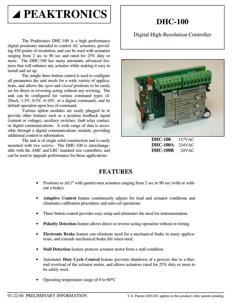
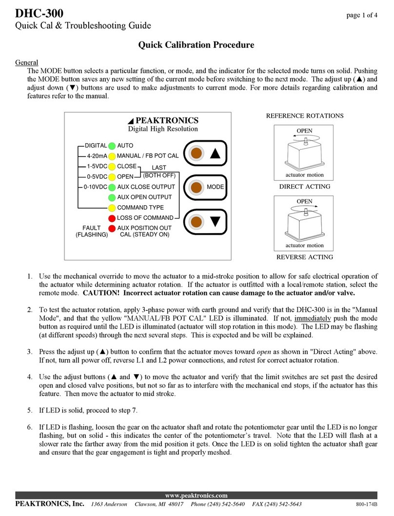
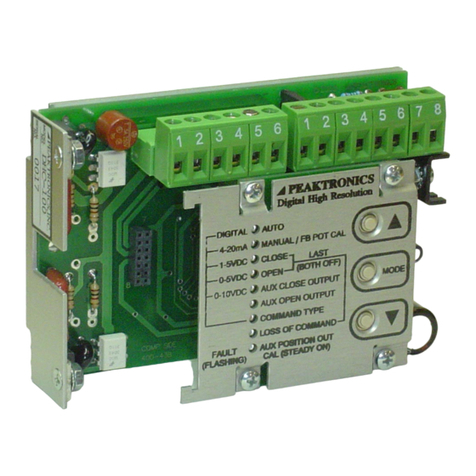
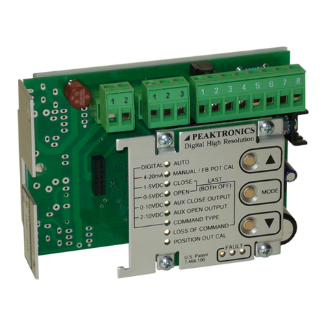
Peaktronics AMC-103 User manual

PEAKTRONICS
The Peaktronics AMC-103 AC Motor Controller is
a compact module that is intended for controlling small AC
actuator motors of up to 2A. The AMC-103 is very well
suited for applications where space constraints within the
actuator would not allow the mounting of conventional mo-
tor controllers.
The AMC-103 is used for proportional positioning
of the actuator. An external command signal of 0-5V, 0-
10V, 4-20mA, or 1-5V is compared to a feedback signal
from a potentiometer. This in turn will energize one of the
AC outputs (open or close) to power the actuator until the
feedback signal matches the command signal, at which time
the controller's AC output is turned off and the actuator mo-
tor stops. If the command signal is lost or disconnected, the
unit interprets this as a zero command signal, and therefore
moves the actuator to the position associated with the zero
adjustment.
Non-interactive Zero and Span adjustments allow
easy field calibration, and the Deadband adjustment allows
control of faster actuators. The unit includes a red LED
indicator (for the open output), a green LED (for the close
output), and an on-board replaceable fuse.
The unit is available in versions for 117VAC ±10%
(AMC-103), 234VAC ±10% (AMC-103A), and 24VAC
±10% (AMC-103B) and provides optical isolation between
the input signal and the AC outputs. Its solid construction
body makes it rugged and easy to mount (two #6 through
holes are provided). Screw terminals and a wiring diagram
on the unit allow for easy field installation.
AMC-103
AC Motor Controller, 2A
AMC-103
AMC-103A
AMC-103B
ZERO SPAN
PEAKTRONICS
MODEL
NO. SERIAL
NO.
DEADBAND
4-20mA 1-5V 0-10V 0-5V
JP1
JP2
JP2
JP1
Close Output
LED
(GREEN)
AMC-103
700-31A
ADDITIONAL FEATURES
•Miniature size fits in the smallest actuators.
•No external motor resistors are required.
•+12V output for powering a command input 4-20mA transmitter, or a position feed-
back transmitter (either 4-20mA or 0-5/10V).
•Operating temperature range of 0 to 60°C

AMC-103
2 PEAKTRONICS
OUTLINE
AMC-103
AMC-103A
AMC-103B
117VAC
234VAC
24VAC
NEUTRAL
LINE
OPEN OUTPUT
COMMON
CLOSE OUTPUT
(+) 0-5V / 0-10V IN
(+) 4-20mA / 1-5V IN
SIGNAL GND
+12V OUT
+5V OUT
WIPER
GND
3.00"
3.00"
1.50"
0.70"0.65"
DEADBAND
ZERO
(2) #6 clear hole
2.40"
WIRING
DIAGRAM
LABEL
JP1
JP2
RED LED (open)
GREEN LED (close)
SPAN
FUSE
1-5V
0-10V
0-5V
4-20mA
INPUT SIGNAL
RANGE JP1 JP2
INPUT SIGNAL

AMC-103
PEAKTRONICS 3
BLOCK DIAGRAM
FEEDBACK
POT
ACTUATOR
POWER / SIGNAL
NOTE: See input signal
configurations for more
information.
WIPER
GND
+5V OUT
LINE
NEUTRAL
(+) 0-5V / 0-10V INPUT
(+) 4-20mA / 1-5V INPUT
SIGNAL GND
+12V OUT
optional
brake
coil
LIMIT SWITCH
LIMIT SWITCH
THERMAL SWITCH
CLOSE
OPEN
AMC-103
OPEN
OUTPUT
CLOSE
OUTPUT
COMMON
OPEN
DESCRIPTION
The AMC-103 comes in three versions to accom-
modate different voltage applications. The AMC-103 is
rated for 117 VAC ±10%; the AMC-103A is rated for 234
VAC ±10%, and the AMC-103B is rated for 24 VAC
±10%. The unit is equipped with screw terminals, allowing
for easy field wiring. The unit also has a label that provides
convenient information for wiring and locating the adjust-
ments. Two mounting holes are provided that allow easy
mounting with standard #6 screws. See Outline infor-
mation for more details.
CAUTION ! These units are intended to be
mounted in an appropriate enclosure to avoid
electrical shocks. High voltages are present
on the outside of the unit when power is ap-
plied. AC power should be disconnected
prior to any wiring of these units. A heater
and thermostat should be used where conden-
sation may occur.

AMC-103
4 PEAKTRONICS
POWER
Power is connected to the terminals marked LINE
and NEUTRAL. The unit does not have an earth ground
connection; earth ground should be connected to the body
of the actuator. The fuse installed on the unit is rated for
maximum output current that can be safely delivered by
the AC outputs. Replacement fuses must not exceed the
maximum rating of 2.5A in order to prevent damage to the
unit. Smaller fuse sizes can be used with smaller motors -
consult the actuator manufacturer for appropriate fuse size
and type.
MOTOR and FEEDBACK POT
The actuator motor and feedback potentiometer are
connected as shown in the block diagram. The OPEN ter-
minal should be connected to the motor winding that moves
the actuator toward the open position, and conversely, the
CLOSED terminal is connected to the winding that moves
the actuator toward the closed position. The COMMON
terminal is the neutral or common wire to the motor wind-
ings. The AMC-103 is suitable for powering most dynamic
brakes used with electric actuators; however, consult the
actuator manufacturer for more information.
The feedback potentiometer wiper must be con-
nected to the WIPER terminal. One end of the potenti-
ometer is connected to the +5V OUT terminal, and the oth-
er is connected to the GND terminal. The potentiometer
should be connected so that when the actuator moves to-
wards the open position, the potentiometer's resistance be-
tween the WIPER and GND terminals will increase. This
can also be measured as a voltage - the voltage between the
WIPER and GND terminals should increase when the actu-
ator moves towards the open position. If the potentiometer
is wired incorrectly, the typical response of the unit will be
to run the actuator to the full open or closed position, re-
gardless of the command signal input, and the correspond-
ing output indicator remains on.
The feedback potentiometer should be mounted to
provide a proper feedback signal through the entire range
between the open and closed positions. For best results,
position the actuator to the midway point between the open
and closed positions; then adjust the feedback potentiome-
ter for approximately 2.5 VDC (or 1/2 of the potenti-
ometer's resistance) between the WIPER and GND termi-
nals.
Since the feedback potentiometer is crucial for
proper operation of the AMC-103, the following items
should be carefully observed:
1 - Potentiometer resistance should be a value from
1K to 10K ohms.
2 - The potentiometer should be a linear taper type.
3 - The potentiometer must be properly wired to pro-
vide the correct feedback signal.
4 - The potentiometer must be properly and securely
mounted in order to provide a reliable feedback
signal.
COMMAND SIGNAL
An appropriate command signal, either 0-5V, 0-
10V, 4-20mA, or 1-5V, should be connected to the appro-
priate terminal (as shown in the Block Diagram) while
using the SIGNAL GND terminal as the return signal
ground. The AMC-103 must be configured for the type of
command signal that is to be used. Jumper plugs JP1 and
JP2 should be properly installed (as shown in the Outline)
prior to operating the unit.
+12V OUT
The +12V OUT terminal provides an auxiliary
+12VDC output that can be used to power a command
input 4-20mA transmitter, or a position feedback transmit-
ter (either 4-20mA or 0-5/10V). Note that only one
transmitter can be powered by the AMC-103. When pow-
ering a 4-20mA transmitter with the +12V OUT, care
should be taken to insure that the total resistance of all
devices connected in the 4-20mA loop does not exceed
300 ohms. See Wiring Diagrams for various applications.
OUTPUT INDICATORS
The AMC-103 has on-board indicators that identi-
fy when one of the motor outputs is turned on. When the
open output is turned on, the red LED indicator will turn
on, and when the close output is turned on the green LED
indicator will turn on (see Outline).
Many actuators are equipped with limit switches
at the open and closed positions that are intended to dis-
connect power to the motor to prevent mechanical dam-
age. For this reason, it is possible that the AMC-103 will
indicate that one of the motor outputs is turned on when
the actuator is not in motion. However, it should be noted
that when the indicator is on, power is applied to the mo-
tor output.

AMC-103
PEAKTRONICS 5
CALIBRATION
The non-interactive zero and span adjustments of
the AMC-103 allows for easy calibration once the unit is
installed. After insuring that the motor outputs and feed-
back potentiometer are wired to provide a proper feedback
signal, as described under "MOTOR and FEEDBACK
POT", follow these steps to calibrate the unit (see Outline
for the location of the adjustments):
1 - Apply AC power to the unit, and set the command
input signal to minimum:
0V for 0-5V input type
0V for 0-10V input type
1V for 1-5V input type
4mA for 4-20mA input type
2 - Adjust the "Zero" adjustment so that the actuator
moves to the desired closed position. If the de-
sired position cannot be achieved, check that the
feedback potentiometer provides a feedback sig-
nal as described under "MOTOR and FEED-
BACK POT"; also, check the position of the limit
switches.
3 - If the actuator is hunting for position, turn the
"Deadband" adjustment clockwise until hunting
stops. If the actuator is not hunting for position,
turn the "Deadband" adjustment counterclockwise
until the actuator begins to hunt; then turn the
"Deadband" adjustment slightly clockwise until
hunting stops.
WARNING! Actuator failure may occur if the
"Deadband" adjustment is set to allow continuous
hunting. This can cause excessive wear of motor
bearings, gear train, dynamic brake, and feedback
potentiometer. Hunting can also cause the inter-
nal temperature of the actuator housing to rise to a
level that exceeds the maximum rating of the
AMC-103, 60°C.
4 - Set the command signal input to maximum:
5V for 0-5V input type
10V for 0-10V input type
5V for 1-5V input type
20mA for 4-20mA type
5 - Adjust the "Span" adjustment so that the actuator
moves to the desired open position. If the desired
position cannot be achieved, check the position of
the limit switch.
NOTE: The "Zero" adjustment is an offset set-
ting rather than an absolute setting. Should the
"Zero" adjustment be changed, the "Span" ad-
justment should be checked for the desired open
position. Setting of the "Span" adjustment has no
affect on the "Zero" adjustment.
6 - To check proper operation and linearity, set the
command signal to halfway:
2.5V for 0-5V input type
5V for 0-10V input type
3V for 1-5V input type
12mA for 4-20mA input type
Verify that the actuator's position is midway be-
tween the open and closed positions.
REVERSE ACTING CALIBRATION
When converting a direct acting actuator to a re-
verse acting actuator, two changes in wiring must be
made:
1 - Reverse the feedback potentiometer wires connect-
ed to +5V OUT and GND.
2 - Reverse the motor wires connected to OPEN
OUTPUT and CLOSE OUTPUT.
NOTE: DO NOT reverse the input signal polari-
ty. Also, make sure that both wiring changes are
made - if only one is made, the actuator will run to
either full open or full closed.
After the wiring changes have been made, refer to CALI-
BRATION for setting the zero and span adjustments.

AMC-103
6 PEAKTRONICS
SPECIFICATIONS
POWER REQUIREMENTS
AMC-103: 117VAC ±10%, 50/60 Hz
AMC-103A: 234VAC ±10%, 50/60 Hz
AMC-103B: 24VAC ±10%, 50/60 Hz
12 VA typical (not including output load)
Fuse Type: 2.5A TR5 Time Delay (replaceable)
COMMAND SIGNAL INPUT
Input Impedance
0-5 VDC Input: 5K ohms
0-10 VDC Input: 10K ohms
4-20 mA Input: 250 ohms ±1%
1-5 VDC Input: 1M ohms minimum
FEEDBACK SIGNAL INPUT
Input Voltage: 0 to 5 VDC
External Feedback Potentiometer: 1K ohm to 10K ohms
+12V OUTPUT
12VDC @ 15mA maximum
10VDC @ 28mA maximum
AC MOTOR OUTPUTS
Off-state Leakage Current: <15mA
Maximum Load Current @ 60°C: 2A
CONTROL ADJUSTMENTS
Zero: adjustable throughout feedback signal range
Span: adjustable throughout command signal range
Deadband: adjustable from 0.12% to 2.1% of full feedback range
ENVIRONMENTAL
Operating Temperature Range: 0 °C to 60 °C
Storage Temperature Range: -40 °C to 85 °C
Relative Humidity Range: 0 to 90 % (noncondensing)

AMC-103
PEAKTRONICS 7
WIRING DIAGRAMS
Input Signal Configurations
4-20mA Input using a self powered transmitter
AMC-103
GND
4-20mA
4-20mA/
1-5V
SIGNAL
Sourcing
or
Sinking
output
NOTE: When using a sinking com-
mand signal, a loop isolator will be
required to connect a position feed-
back transmitter.
135 ohm Slide Wire
using the 4-20mA Input Signal
AMC-103
XMA-108
135 ohm
Slide
Wire
4-20mA
Transmitter
OPEN
OUT
+12V
1-5V
4-20mA/
NOTE: When using a position feed-
back transmitter with this configura-
tion, it must be powered by an exter-
nal power supply.
0-5/0-10V Input using digital-to-analog card
AMC-103
NOTE: Set JP1 and JP2 for appro-
priate input type.
0-5V
or
0-10V
DAC
SIGNAL
GND
0-5V/
0-10V
Remote Command Pot
using the 4-20mA Input Signal
AMC-103
MLT-100A
XMA-104A
Command
Pot
4-20mA
Transmitter
(includes dial and knob)
CW
RED
WHT
BLK
OUT
+12V
1-5V
4-20mA/
NOTE: When using a position feed-
back transmitter with this configura-
tion, it must be powered by an exter-
nal power supply.

AMC-103
PEAKTRONICS, Inc.
800-110B
WIRING DIAGRAMS
Special Applications
Connecting a position feedback transmitter
Feedback Monitor
XMA-105
XMA-106
w
SPAN
ZERO
FEEDBACK
POTENTIOMETER
AMC-103
+12V OUT
SIGNAL GND
WIPER
+5V OUT
GND
XMA-105 (4-20)
4-20mA output
XMA-106 (5/10)
0-5V/10V output NOTE: Feedback potentiometer wiper
should have 1/2 the total pot resistance
at midstroke in order to guarantee zero
and span calibration of transmitter.
Split range control
Calibrate unit #1 to open and close with 4 to 12 mA,
and unit #2 to open and close with 12 to 20 mA.
Note, the ratio between the feedback pot rotation to
the actuator shaft rotation must be 1:1.
OPEN
OUTPUT CLOSE
OUTPUT
SIGNAL
GND
COMMON
4-20mA
4-20mA
Command
Signal
CLOSE
OUTPUT
OPEN
OUTPUT COMMON
1-5VSIGNAL
GND
Motor
Motor
NOTE: Limit switches
must be used to stop
actuator travel!
AMC-103 #1
(configured for 4-20mA input) (configured for 1-5V input)
AMC-103 #2
This manual suits for next models
2
Table of contents
Other Peaktronics Controllers manuals

Peaktronics
Peaktronics DHC-300A User manual

Peaktronics
Peaktronics DHC-400 User manual

Peaktronics
Peaktronics DHC-100 User manual

Peaktronics
Peaktronics DHC Series User manual

Peaktronics
Peaktronics DHC-301 User manual

Peaktronics
Peaktronics DHC-300 User manual

Peaktronics
Peaktronics DHC-301 User manual

Peaktronics
Peaktronics DHC-100 User manual
Popular Controllers manuals by other brands

SIIG
SIIG UltraATA 133 PCI Quick installation guide

industrie technik
industrie technik SE25F230 instruction manual

Mankenberg
Mankenberg UV 3.5 ATEX H2 Original operating manual

TAOS
TAOS TSL2571 EVM2 Kit quick start guide

Panasonic
Panasonic FP7 Series Command reference manual

BENSHAW
BENSHAW RediStart MX2 SEP user manual