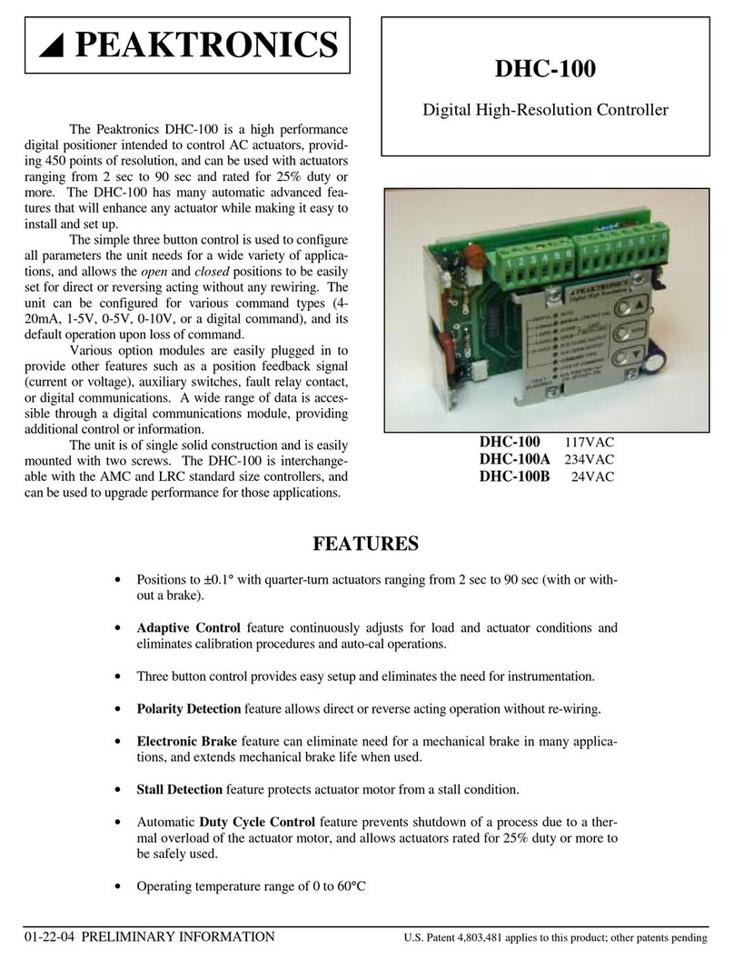
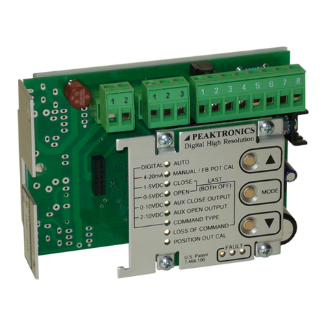
Peaktronics DHC-400 User manual

U.S. Patent 7,466,100 applies to this product
PEAKTRONICS
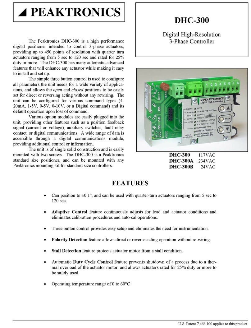
The Peaktronics DHC-400 is a high performance
digital positioner intended to control DC actuators, provid-
ing 450 points of resolution with quarter turn actuators
ranging from 2 sec to 120 sec. The DHC-400 has many
automatic advanced features that will enhance any actuator
while making it easy to install and set up. The DHC-400
can replace a DMC-100 standard size controller in most
applications to upgrade performance.
The simple three button control is used to configure
all parameters the unit needs for a wide variety of applica-
tions, and allows the open and closed positions to be easily
set for direct or reversing acting without any rewiring. The
unit can be configured for various command types (4-
20mA, 1-5V, 0-5V, 0-10V, 2-10V, or a digital command)
and its default operation upon loss of command. The mul-
ticolor LED Fault indication displays up to 15 different
conditions (including "Low Battery Voltage").
Various option modules are easily plugged into the
unit, providing other features such as a position feedback
signal, auxiliary switches, fault relay contact, or digital
communications. A wide range of data is accessible
through a digital communications module, providing addi-
tional control or information.
DHC-400
DC Digital High-Resolution Controller
FEATURES
•10 to 30 VDC operating voltage range with motors rated up to 60A locked rotor or 10A run-
ning current.
•Solid state motor driver with thermal and overcurrent protection provides reliable service be-
yond the life of the actuator motor.
•Positions to ±0.1°with quarter-turn actuators ranging from 2 sec to 120 sec (with or without a
mechanical brake). Electronic Brake feature can eliminate mechanical brake.
•Adaptive Control feature continuously adjusts for load and actuator conditions and eliminates
calibration procedures and auto-cal operations.
•Polarity Detection feature allows direct or reverse acting operation without re-wiring.
•Stall Detection feature protects actuator motor from a stall condition.
•Adjustable Motor Current Trip (0-12A) setting limits actuator torque and battery/power sup-
ply current requirements.
•Electronic Surge Limiting reduces wire size and battery/power supply requirements to 20%
of locked rotor current.
•Automatic Duty Cycle Control feature prevents motor damage due to overheating and pre-
vents shutdown of a process due to a thermal overload switch.
•Operating temperature range of 0 to 60°C

DHC-400
2 U.S. Patent 7,466,100 applies to this product PEAKTRONICS
OUTLINE
FRONT PANEL
+2.5V 1
2
3
4
5
6
WIPER
GND
MOTOR 2 OUTPUT
MOTOR 1 OUTPUT
to Motor
to Feedback Pot
1
2
3
4
6
+5V OUT
EARTH
BAT POS
to DC Power
to Signal
ELECTRICAL
CONNECTIONS
J1
J2
5
J3
OPTION MODULE
CONNECTOR
1
2
OVERRIDE INPUT
to Auto/Manual Station J7
GND
7
8
LIMIT COMMON
LIMIT SW1
LIMIT SW2
COMMAND ( )
BAT NEG
COMMAND (+)
AUTO
MANUAL / FB POT CAL
CLOSE
OPEN
AUX CLOSE OUTPUT
AUX OPEN OUTPUT
COMMAND TYPE
LOSS OF COMMAND
DIGITAL
4-20mA
1-5VDC
0-5VDC
0-10VDC
LAST
MODE
Digital High Resolution
(BOTH OFF)
PEAKTRONICS
POSITION OUT CAL
FAULT
2-10VDC
J1 J2
J3
FUSE
3.50" 0.25"
0.25"
#6 clear hole
(2) places
1.36"
1.36"
1.32"
87654321 654321
J7
TRIP
ADJUST

DHC-400
PEAKTRONICS U.S. Patent 7,466,100 applies to this product 3
BLOCK DIAGRAM
FEEDBACK
POT
J1
J2
WIPER
2
GND
3
+2.5V
1
LIMIT SW1
7
LIMIT COMMON
6
MOTOR 1
4
MOTOR 2
5
1
BAT POS
2
BAT NEG
6
+5V OUT
4
COMMAND (+) 5
COMMAND ( )
+V
LIMIT SW2
8
3
EARTH
10-30
VDC see WIRE TABLE
_
NOTE: See input sig-
nal configurations for
more information.
EARTH
NOTE: Battery nega-
tive must be connected
to earth ground at pow-
er source.
DHC-400
ACTUATOR
AUTO/MANUAL
STATION
J7 2
1GND
OVERRIDE
INPUT
See Special Applications
OVERRIDE
POWER / SIGNAL
DESCRIPTION
The DHC-400 is rated for motors with up to 60A
locked rotor or 10A running currents and has an operating
voltage range from 10VDC to 30VDC. The unit is easily
mounted with 2 screws and is equipped with removable
screw terminals that provide for easy field wiring. The
unit's size and mounting allows the DHC-400 to replace the
DMC-100 series controllers in most applications with min-
imal rewiring.
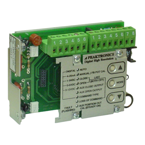
The simple three button control (MODE, ▲, and
▼) allows the user to perform a complete set-up from the
unit itself without the need for any instrumentation. The
adaptive control feature of the DHC-400 eliminates the
need for any calibration steps. In the simplest application,
only the closed and open positions need to be set and the
unit automatically and continuously sets all other parame-
ters when placed in the AUTO mode.
POWER / SIGNAL (J2)
The positive terminal of the DC power source is
connected to pin 1 while the negative terminal connects to
pin 2. When the DHC-400 is mounted to a metal bracket
or directly to the actuator case, pin 3 provides a terminal
for an earth ground connection to the actuator body. In
applications where the actuator body is non-metallic or is
electrically isolated from earth ground, pin 3 must be con-
nected to earth ground to prevent static voltage buildups.

DHC-400
4 U.S. Patent 7,466,100 applies to this product PEAKTRONICS
Transferring DC power can be inefficient, therefore
care should be taken to use appropriate wire sizes. The size
wire required depends on the locked rotor motor current
and the length of wire to be used. See the Wire Table for
more information.
An appropriate command signal, either 0-5V, 0-
10V, 1-5V, 2-10V, or 4-20mA, should be connected to pin
5 (as shown in the Block Diagram) while using pin 4 as
the return signal ground. See Wiring Diagrams, Input Con-
figurations, for wiring details. The DHC-400 must be con-
figured for the type of command signal that is to be used
(see COMMAND TYPE).
Pin 6 of J2 provides an auxiliary +5V output
which can be used to connect a command potentiometer.
By connecting one end of a potentiometer to pin 6, the
other end to pin 4, and the wiper to pin 5, a local control
knob can be implemented. Pin 4 will also need to be con-
nected to pin 2 (BAT NEG) for this application.
ACTUATOR (J1)
The actuator motor and feedback potentiometer
are connected to J1 as shown in the Block Diagram. The
feedback potentiometer wiper must be connected to pin 2,
while one end is connected to pin 1 and the other end to
pin 3. The Polarity Detection feature of the DHC-400
automatically determines which polarity to apply to the
motor based on where the open and closed positions are
set; this feature also eliminates the need to rewire the unit
for direct or reverse acting applications.
Many actuators include limit switches that are used
to turn off the motor when the extreme ends of travel have
been reached. Limit switches should be wired to pins 6, 7,
and 8 as shown in the Block Diagram. If limit switches are
not used, pins 7 and 8 must be connected to pin 6 (note, if
pins 7 and 8 are not connected to pin 6, the DHC-400 will
not be able to control the motor outputs).
When the ▲and ▼buttons are used to control
the actuator, the ▲button will connect pin 4 (MOTOR 1)
to BAT POS (J2-1) and pin 5 (MOTOR 2) to BAT NEG
(J2-2) as long as pin 7 (LIMIT SW1) is connected to pin 6
(LIMIT COMMON). Likewise, the ▼button will con-
nect pin 5 to BAT POS and pin 4 to BAT NEG as long as
pin 8 (LIMIT SW2) is connected to LIMIT COMMON.
Since pins 4 and 5 are alternately connected to BAT POS
(J2-1) and BAT NEG (J2-2), care should be taken not to
connect the motor output pins to any other terminals. See
MANUAL/FB POT CAL for more details.
The DHC-400 provides a dynamic braking feature
that can eliminate the need for a separate brake. When the
DHC-400 turns off the motor outputs, pins 4 and 5 are in-
ternally connected to the BAT NEG pin (J2-2); this has the
effect of shorting the motor leads together, thus braking the
motor motion. When power is removed from the DHC-
400, the electronic braking feature is disabled. In some ap-
plications, a brake is required for mechanical reasons, such
as avoiding back driving the motor; the DHC-400 is suit-
able for powering most brakes, however, consult the actua-
tor manufacturer for more information.
OVERRIDE (J7)
J7 provides a simple 2-wire connection that can
override the DHC-400 to perform a variety of external
control functions. Using an appropriate interface module,
commonly used auto/manual station switches are easily
implemented with low voltage/low current switches. See
Special Applications for more details. The factory in-
stalled jumper between pins 1 and 2 enables normal opera-
tion of the DHC-400 and must be installed if the external
override functions are not used.
MODE
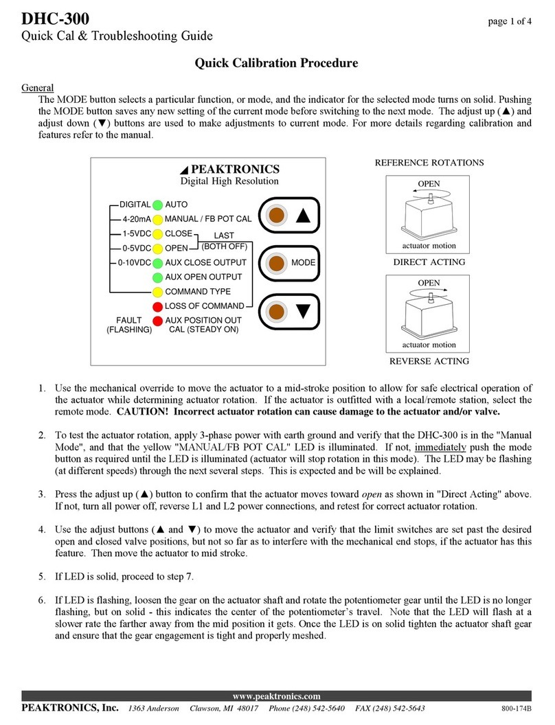
The MODE button is used to select the desired
function of operation. When the MODE button is pressed,
the unit will switch to the next function and the appropri-
ate LED indicator will turn on to let the user know which
function is selected. Except for the MANUAL/FB POT
CAL mode, the associated mode indicator will be steady
on; for some of the modes other indicators will flash to
indicate specific settings associated with the mode. Each
of the modes are described in more detail in the following
sections.
If a 0-5V or 0-10V command signal is used, the
LOSS OF COMMAND function cannot be used. The
MODE button will skip over the LOSS OF COMMAND
mode when the unit is configured for a 0-5V or 0-10V
command signal (see COMMAND TYPE). When the
OVERRIDE mode is enabled (see OVERRIDE MODE),
the MODE button is disabled and the Manual/Pot Cal in-
dicator will turn on steady.
ADJUST UP (▲) and ADJUST DOWN (▼)
The adjust up (▲) and adjust down (▼) buttons
are used to adjust the setting of any given function. When
a function is selected by the MODE button, the adjust but-
tons will affect that function only. Note, that the AUTO
mode does not have any adjustable settings, and therefore,
the adjust up (▲) and adjust down (▼) buttons have no
effect. Also, the adjust buttons are disabled in the
OVERRIDE mode.

DHC-400
PEAKTRONICS U.S. Patent 7,466,100 applies to this product 5
OVERRIDE MODE
The OVERRIDE mode is not selected by the
MODE button and can be enabled at anytime by connect-
ing a resistance greater than 250 ohms to the Override In-
put (J7 pin 1 and pin 2). While the OVERRIDE mode is
enabled, the MODE button and adjust buttons are dis-
abled, and the Manual/Pot Cal indicator will turn on
steady to indicate that the unit is being controlled by the
Override Input. Shorting J7 pin 1 to pin 2 returns the unit
to normal operation and the previously selected mode.
Controlling the DHC-400 from the Override Input
is accomplished by connecting a specific resistance to se-
lect a specific operation. The table below defines the op-
erations and their associated resistance. See Special Ap-
plications for details on using the Override Input for an
Auto/Manual Station.
RESISTANCE OPERATION
> 4.3K ohms OFF
3.3K ohms ±5% LATCH
2K ohms ±5% OPEN
1.2K ohms ±5% CLOSE
510 ohms ±5% STOP
The OPEN function will operate the motor in the
open direction as set by the OPEN mode, while the
CLOSE function operates the motor in the closed direction
as set by the CLOSE mode. The LATCH function will
maintain the previously selected function; this allows
momentary switches to be used for the OPEN and CLOSE
functions. The OFF and STOP functions turn the motor
off, which also unlatches the OPEN or CLOSE functions.
Note that the OPEN and CLOSE functions may
work in reverse until the open and closed positions are set
by the OPEN and CLOSE modes. The DHC-400 will au-
tomatically turn the motor off when the open or closed
positions are reached. However, if a feedback fault occurs
(see FAULT INDICATOR), the motor will be turned on
for a period of 15 minutes in the selected direction. For
this reason, limit switches should be used when using the
OVERRIDE mode, and should be set to a position accept-
able for the application. The 15 minute period can also be
terminated using the OFF or STOP function.
The motor is also automatically turned off if the
DHC-400 detects a stall (see STALL DETECTION). An
OPEN or CLOSE operation can be attempted again after
switching to the OFF, LATCH, or STOP functions first.
The motor is also turned off if a motor current trip
is detected (see TRIP SETTING). If the trip occurred dur-
ing an OPEN operation, the OPEN operation is disabled
until the trip condition is corrected. The CLOSE opera-
tion may be used to attempt to clear the trip condition (by
causing a certain amount of motion in the closed direc-
tion). Likewise, if a trip occurs during a CLOSE opera-
tion, the OPEN operation can be used for clearing the trip.
If a trip occurs in both directions (i.e., before the first trip
can be cleared), the trip can only be cleared by a mechani-
cal override mechanism, or by using the MANUAL mode
from the DHC-400 front panel, or by powering the DHC-
400 down and back up.
AUTO
The AUTO function is the normal mode of opera-
tion for the DHC-400; all the other functions are used to
set up the unit. While in AUTO, the unit can be controlled
by various external signals, some of which can be selected
by the COMMAND INPUT function. When the unit is
not in the AUTO mode, all external control signals de-
scribed below will be disabled.
Once the open and closed positions have been set,
the AUTO mode will control the position of the actuator
according to the command input signal. For an input sig-
nal of 0V (for 0-5V or 0-10V input), 1V (for 1-5V input),
2V (for 2-10V input), 4.0 mA (for 4-20mA input), or 0%
(for a digital input), the DHC-400 will position the actua-
tor to the closed position as set by the user. Conversely,
an input of 5V, 10V, 20mA, or 100% will position the
actuator to the defined open position.
When the DHC-400 is configured to use a 0-5V,
0-10V, 1-5V, 2-10V, or 4-20mA command, the command
signal should be connected to the appropriate pins on J2.
When the DHC-400 is configured for a Digital command
type, an appropriate communications option module must
be installed. A communications module may be installed
when using one of the analog command types and can be
used to override the analog command. The AUTO indica-
tor will flash whenever the unit is being controlled by the
communications module.
MANUAL/FB POT CAL
The MANUAL/FB POT CAL function allows
manual operation of the actuator by using the adjust but-
tons (▲and ▼) without affecting any other settings with-
in the DHC-400. When the ▲button is pressed, the MO-
TOR 1 (J1-4) output is connected to BAT POS (J2-1), and
the MOTOR 2 (J1-5) output is connected to BAT NEG
(J2-2). The ▼button connects MOTOR 1 to BAT NEG
and MOTOR 2 to BAT POS. Whether the actuator moves
toward the open or closed position depends on which mo-
tor wire is connected to J1-4 and J1-5.
The POT CAL feature provides an indication of
the feedback potentiometer's setting. When the MANU-
AL/POT CAL function is selected, the Manual/Pot Cal
indicator will turn on - it may flash or be on steady, de-

DHC-400
6 U.S. Patent 7,466,100 applies to this product PEAKTRONICS
pending on the actuator position. The indicator will be on
steady whenever the DHC-400 detects that the feedback
potentiometer is at midrange of its rotation. As the actua-
tor moves, causing the feedback potentiometer to move
away from midrange, the indicator will begin to flash, and
the indicator will flash at a decreasingly slower rate as the
actuator moves further away from midrange.
By using the adjust buttons to position the actua-
tor to midstroke (half way point between the desired open
and closed positions), the feedback potentiometer can then
be adjusted until a steady light occurs. This insures that
the feedback potentiometer has maximum range to reach
the open and closed positions.
CLOSE
The CLOSE function is used to set the desired
closed position; however, prior to doing this, the feedback
potentiometer should be checked for optimum position
(see MANUAL/POT CAL), and the limit switches should
be set outside of the operating range (see LIMIT
SWITCHES). In the CLOSE function, the adjust buttons
are used to set the actuator to any desired position, and
upon pressing the MODE button (to select the next func-
tion, OPEN), the DHC-400 will retain the setting as the
defined closed position.
Upon selecting the CLOSE function, the DHC-
400 will begin moving the actuator to the previously set
closed position; it is not necessary to make an adjustment
if the unit has been previously set to the desired position.
A command signal input of 0V, 1V, 2V, 4mA, or 0% au-
tomatically corresponds to the defined closed position.
OPEN
The OPEN function works the same way as the
CLOSE function with the exception that the adjust buttons
are used to set the desired open position. As with the
CLOSE function, upon selecting the OPEN function, the
actuator will move to the previously set open position.
Once the desired position is set, the DHC-400 will auto-
matically associate a command signal input of 5V, 10V,
20mA, or 100% to the open position.
AUX CLOSE OUTPUT
The AUX CLOSE OUTPUT function is used to
set an optional output setting that is associated with the
closed position - an appropriate relay option module is
required to use this output. The adjust buttons are used to
set the actuator to a desired position. Whenever the actua-
tor position falls between the defined closed position and
the Aux Close position, the Aux Close Output indicator
will flash. Additionally, the DHC-400 will turn on a relay
output on the optional relay module - the output can be
used to drive an alarm or merely act as an auxiliary limit
switch.
Upon selecting the AUX CLOSE OUTPUT func-
tion, the DHC-400 will begin moving the actuator to the
previously set position. It is not necessary to make an ad-
justment if the unit has been previously set to the desired
position.
AUX OPEN OUTPUT
The AUX OPEN OUTPUT function is used to set
an optional output setting that is associated with the open
position - an appropriate relay option module is required
to use this output. The adjust buttons are used to set the
actuator to a desired position. Whenever the actuator po-
sition falls between the defined open position and the Aux
Open position, the Aux Open Output indicator will flash.
Additionally, the DHC-400 will turn on a relay output on
the optional relay module - the output can be used to drive
an alarm or merely act as an auxiliary limit switch.
Upon selecting the AUX OPEN OUTPUT func-
tion, the DHC-400 will begin moving the actuator to the
previously set position. It is not necessary to make an ad-
justment if the unit has been previously set to the desired
position.
COMMAND TYPE
The COMMAND TYPE function is used to con-
figure the command signal input for either 4-20mA, 1-5V,
0-5V, 0-10V, 2-10V, or digital so as to match the type of
command signal being used. Upon selecting the COM-
MAND TYPE function, the Command Input indicator will
turn on steady, while the indicator for the selected type
will flash. Use the adjust buttons (▲or ▼) to select the
desired input type. The selection will be saved when the
MODE button is pressed, which will also advance the unit
to the LOSS OF COMMAND function.
LOSS OF COMMAND
When using 1-5V, 2-10V, 4-20mA, or a Digital
input type for the command signal, the DHC-400 will de-
tect when the command signal is lost or out of range. A
loss of command condition is detected whenever the input
is disconnected, the input becomes less than 0.75V (for 1-
5V input), 1.5V (for 2-10V input) or 3mA, or the input is

DHC-400
PEAKTRONICS U.S. Patent 7,466,100 applies to this product 7
connected backwards. An out of range condition is de-
tected whenever the input becomes greater than 5.25V (for
1-5V input), 10.5V (for 2-10V input), or 21mA. If the
DHC-400 detects a loss of command, a fault will be indi-
cated (see FAULT INDICATORS), and the actuator will
be moved to one of three preset positions: the open posi-
tion, the closed position, or the position last attained prior
to losing the command signal. The LOSS OF COM-
MAND function is used to set the desired default position.
When the LOSS OF COMMAND function is se-
lected, the adjust buttons are used to set the default posi-
tion. The DHC-400 indicates the selected default setting
by flashing the Open function indicator for the open de-
fault position, or it will flash the Close function indicator
for the closed default position. When neither indicator is
on, then the "last position" default is selected.
When a 0-5V or 0-10V command signal is used, a
loss of command signal cannot be reliably detected.
Therefore, if the unit is configured for a 0-5V or 0-10V
command signal (see COMMAND INPUT), the MODE
button will not select the LOSS OF COMMAND function.
However, the DHC-400 can detect when a 0-5V or 0-10V
command signal is out of range (i.e., greater than 5.25V or
greater than 10.5V) or connected backwards. When an
out of range condition is detected for a 0-5V or 0-10V in-
put, the motor is turned off (leaving the actuator in its "last
position") and a fault will be indicated (see FAULT IN-
DICATORS).
POSITION OUT CAL
The POSITION OUT CAL function is used to
calibrate an optional feedback transmitter output. An ap-
propriate transmitter option module is required to use this
feature. When the POSITION OUT CAL function is first
selected (by pressing the MODE button while in the LOSS
OF COMMAND function), the CLOSE indicator will
flash, and the current associated with the closed position
will appear at the option module output. If desired, the
output can be adjusted (using the adjust buttons) to any
value from 4 to 20mA. The new setting is saved when the
MODE button is pressed.
Pressing the MODE button will leave the unit in
the POSITION OUT CAL function except that the OPEN
indicator will flash, and the output current associated with
the open position will appear at the option module output.
Like the closed setting, the output can be adjusted to any
current from 4 to 20mA. The new setting is saved when
the MODE button is pressed, which also selects the AU-
TO mode.
FAULT INDICATORS
The DHC-400 detects various fault conditions that
prohibit the unit from controlling the actuator. A combi-
nation of the three Fault indicators (red, yellow, and
green) will turn on or flash to indicate a specific detected
fault. If an appropriate relay option module is installed,
the Fault relay output on the option module will turn off
(indicating a fault) when any of the Fault indicators turn
on or flash. A communications option module can also
read the specific conditions causing a fault. Note that a
fault condition DOES NOT disable the motor outputs
when manually controlling the actuator with the adjust
buttons; while useful for troubleshooting, care should be
exercised when operating the motor under a fault condi-
tion. The OVERRIDE mode can also operate the motor
when a fault condition exists - see OVERRIDE MODE for
details.
Note that the indicators may not indicate all the
fault conditions that may exist. This means that when the
indicated fault is corrected, the unit may display another
fault that has not been corrected. The table below pro-
vides a summary of the Fault indications which is fol-
lowed by a description of each fault.
RED YEL GRN FAULT
flash OFF OFF Low Battery Voltage
flash flash OFF Motor 1 Stall
flash OFF flash Motor 2 Stall
flash flash flash Double Stall
flash ON OFF Motor 1 Current Trip
flash OFF ON Motor 2 Current Trip
flash ON ON Double Current Trip
ON OFF OFF Battery Over Voltage
ON flash OFF Motor 1 No Motion
ON OFF flash Motor 2 No Motion
ON flash flash Double No Motion
OFF OFF flash Feedback Alarm
OFF flash OFF Loss of Command
OFF ON OFF Command Out of Range
OFF flash flash
Feedback Alarm and
Loss of Command
OFF ON flash
Feedback Alarm and
Command Out of Range
Low Battery Voltage - When the DHC-400 detects that
the battery/power supply voltage connected to BAT POS
(J2-1) and BAT NEG (J2-2) drops below 10V, the motor
outputs are turned off and the DHC-400 suspends all other
operations until the voltage returns to 10V or more. How-
ever, the Low Battery Voltage fault indication will main-
tain for 3 seconds after voltage returns. Since DC motors

DHC-400
8 U.S. Patent 7,466,100 applies to this product PEAKTRONICS
present a large load (from in-rush currents) when turned
on, a weak battery or insufficient power supply may ex-
perience a short voltage drop below 10V until the motor
begins to move. Therefore, the Low Battery Voltage indi-
cation provides warning of batteries in need of recharge or
power supplies that have insufficient current for the appli-
cation.
Motor 1 Stall - A stall condition is detected when no ac-
tuator motion is detected while the Motor 1 output is
turned on and drawing more than 0.5A of motor current.
The fault condition will disable the Motor 1 output only,
and the fault is cleared when the DHC-400 detects a mo-
tion greater than 1.5°in either direction. The fault can be
cleared if 1) the command signal commands a Motor 2
operation, 2) manual operation with the adjust buttons re-
sults in a motion greater than 1.5°, or 3) a mechanical
manual override forces the 1.5°motion, provided the me-
chanical motion is monitored by the feedback pot.
Motor 2 Stall - A stall is detected when no actuator mo-
tion is detected while the Motor 2 output is turned on and
drawing more than 0.5A of motor current. The fault can
be cleared in the same manner as previously described for
a Motor 1 Stall.
Double Stall - If the DHC-400 detects a stall condition in
both directions, both motor outputs will be disabled. The
command signal cannot clear this condition; only manual
operation or a mechanical override can clear the fault.
Alternatively, the DHC-400 can be powered off and then
on to temporarily clear the fault; however, this practice
should be avoided without permanently correcting the
cause of such a fault.
Motor 1 Current Trip - A current trip fault is detected
when the motor current exceeds the current trip setting
(see TRIP SETTING) while the Motor 1 output is turned
on. The fault can be cleared in the same manner as previ-
ously described for a Motor 1 Stall. NOTE: Successive
attempts with manual operation using the adjust buttons
can exceed the torque limit set by the Trip Setting.
Motor 2 Current Trip - A current trip fault is detected
when the motor current exceeds the current trip setting
(see TRIP SETTING) while the Motor 2 output is turned
on. The fault can be cleared in the same manner as previ-
ously described for a Motor 1 Current Trip.
Double Current Trip - If the DHC-400 detects a current
trip fault in both directions, both motor outputs will be
disabled. The fault can be cleared in the same manner as
previously described for a Double Stall.
Battery Over Voltage - Other inductive loads (such as
motors or solenoids) sharing the battery/power supply
connected to BAT POS (J2-1) and BAT NEG (J2-2) can
generate short transient voltages that may cause the supply
voltage to exceed 30V. To prevent damage to the DHC-
400 or the actuator motor, the motor outputs are turned off
whenever the supply voltage exceeds 30V. Upon detect-
ing a voltage above 30V, the Battery Over Voltage fault
indication will turn on and will maintain for 3 seconds
after voltage returns. If an over voltage condition lasts
less than 1 second, the Fault relay output will not turn off.
If the Fault relay output turns off (indicating an over volt-
age lasting longer than 1 second), the output will turn back
on when the voltage returns to 30V or less. Note, earlier
versions of the DHC-400 may not have this feature. Con-
tact Peakronics, Inc. for more information.
WARNING! Exposing the DHC-400 to frequent or con-
tinuous voltages above 30V can damage the unit. The
user should take steps to suppress or eliminate possible
supply voltage conditions above 30V.
Motor 1 No Motion - A no motion fault is detected when
no actuator motion is detected while the Motor 1 output is
turned on and drawing less than 0.5A of motor current.
The fault can be cleared in the same manner as previously
described for a Motor 1 Stall. A stall usually indicates a
heavy mechanical load or stall, while a no motion fault
usually indicates a broken motor wire or disengaged feed-
back pot. Note that a stall cannot be detected in applica-
tions using very small motors (locked rotor currents less
than 0.5A); only a no motion fault can be detected.
Motor 2 No Motion - A no motion fault is detected when
no actuator motion is detected while the Motor 2 output is
turned on and drawing less than 0.5A of motor current.
The fault can be cleared in the same manner as previously
described for a Motor 1 Stall. A no motion fault differs
from a stall as previously describe for a Motor 1 No Mo-
tion fault.
Double No Motion - If the DHC-400 detects a no motion
fault in both directions, both motor outputs will be dis-
abled. The fault can be cleared in the same manner as pre-
viously described for a Double Stall.
Feedback Alarm - A fault condition is detected whenever
the feedback signal is out of range (that is, less than 5% of
the potentiometer value or more than 95% of the potenti-
ometer value), or when any of the potentiometer connec-
tions are broken. Normal operation resumes when the
potentiometer is reconnected or back in range.

DHC-400
PEAKTRONICS U.S. Patent 7,466,100 applies to this product 9
Loss of Command - If the command signal is discon-
nected, the fault indication will remain on until the signal
is reconnected. See LOSS OF COMMAND for details.
Command Out of Range - If the command signal goes
out of range, the fault indication will remain on until the
signal is back in range. See LOSS OF COMMAND for
details.
LIMIT SWITCHES
The actuator's limit switches should be connected
to J1 as described in ACTUATOR (J1) - also see OUT-
LINE and BLOCK DIAGRAM. The limit switches must
be closed throughout the operating range from closed to
open. When Limit Switch 1 opens, Motor 1 operations are
disabled. Likewise, when Limit Switch 2 opens, Motor 2
operations are disabled.
Note that the actuator's limit switches should be
set outside of the operating range set by the CLOSE and
OPEN functions. Limit switches exhibit wide variations,
and the DHC-400 can position the actuator more precisely
at closed and open than the limit switches. A limit switch
serves better as a fail safe device.
After setting the open and closed positions, the
DHC-400 automatically determines which limit switch is
associated with open and closed. When a limit switch is
reached, the appropriate indicator light (CLOSE or OPEN)
will flash. If an appropriate relay option module is in-
stalled, the Fault relay output on the option module will
turn off (indicating a fault) when either of the limit
switches is reached.
TRIP SETTING
The Trip Setting is used to limit the motor cur-
rent and is set using the TRIP ADJUST pot (see OUT-
LINE) as shown below.
(full CW)
12A
(full CCW)
0A
6A
9A3A
The setting should be adjusted to a comfortable
level above the running current expected for the actuator
and its load. When the motor current exceeds the trip set-
ting, the motor is turned off and a fault condition is indi-
cated (see FAULT INDICATORS).
While the Electronic Surge Limiting feature of
the DHC-400 reduces the high in-rush currents during mo-
tor starts, the trip setting is used to reduce the current re-
quired from the battery/power supply when the motor
stalls or encounters an excessive load. Without the trip
setting, a costly high capacity battery/power supply would
be needed to avoid collapse of the battery/power supply
voltage. The combination of the trip setting and electronic
surge limiting allows the use of a more moderate bat-
tery/power supply and smaller gauge wires for a given
length (see WIRE TABLE).
The trip setting essentially performs the same
function as commonly used torque switches. However, it
should be noted that the actuator and valve components
(gears, couplings, seats, etc.) also place a load on the mo-
tor. These components will vary with temperature and
age, and therefore the torque on the load will vary accord-
ingly.
STALL DETECTION FEATURE
The Stall Detection feature of the DHC-400 de-
tects when there is no motion after a certain amount of
time while the motor is turned on (see FAULT INDICA-
TORS). This condition can arise if the motor's stall cur-
rent is less than the current trip setting (see TRIP SET-
TING). If the motor current is greater than 0.5A when no
motion is detected, a stall fault is indicated.
When one of the motor wires is disconnected, no
motion will be detected, but the motor current will be ze-
ro. Therefore, if the motor current is less than 0.5A when
no motion is detected, a no motion fault is indicated.
If the feedback pot is mechanically disengaged, no
motion will be detected, but the motor current will be the
normal running current. Therefore a stall or a no motion
fault may be indicated, depending on whether the running
current is greater or less than 0.5A.
ELECTRONIC BRAKE FEATURE
The Electronic Brake feature of the DHC-400
provides highly reliable and accurate braking of the motor,
and it is a key element in achieving high resolution. A
mechanical brake can still be implemented without inter-
fering with the DHC-400 operation. The Adaptive Con-
trol feature of the DHC-400 automatically compensates
for changes in a mechanical brake's performance due to
temperature or age.

DHC-400
10 U.S. Patent 7,466,100 applies to this product PEAKTRONICS
Mechanical brakes can be useful for providing a
holding brake in the event power to the actuator is lost.
However, mechanical brakes require time to release on
motor start up, and this may cause an increased surge cur-
rent that counteracts the Electronic Surge Limiting fea-
ture. Also, a mechanical brake may not release at lower
voltages, in which case a stall or current trip fault may
occur.
The Electronic Brake feature remains on as long
as the DHC-400 is powered. This could make a mechani-
cal override mechanism difficult to turn. For this reason,
the electronic brake is disabled when the DHC-400 is
placed in the Override Mode via J7 (see Special Applica-
tions).
CAUTION! When using the DHC-400 with a spring re-
turn actuator, the return spring can generate high electrical
energies while back driving the motor that can damage the
DHC-400 motor outputs. In this application, the motor
must be disconnected (usually with a relay) from the
DHC-400 during a spring return operation.
DUTY CYCLE CONTROL FEATURE
The Duty Cycle Control feature of the DHC-400
allows the actuator to be safely used when a process be-
comes unstable, a control loop is not properly set, or when
the motor is subjected to excessive loading. The DHC-
400 accurately monitors the relative heating of the motor
and automatically duty cycles the unit at a safe level.
The Duty Cycle Control feature allows continu-
ous operation of the motor until it detects an excess heat
build up in the motor. At that time, duty cycle operation is
automatically enabled and continues until the motor cools
enough to resume continuous operation. The duty cycle
period is approximately 2 seconds with an on time that
automatically varies depending on the heating of the mo-
tor. While this operation slows down the actuator's opera-
tion, it does not impact the resolution performance of the
DHC-400, and it allows control of the process to be main-
tained without damage to the motor.
OPTION MODULES
Various option modules can be plugged into the
DHC-400 option module connector, J3. Option modules
provide additional features such as position feedback sig-
nals, auxiliary switch outputs, or digital communications.
Contact the factory for the latest available modules. Refer
to the diagram below for instructions on installing an op-
tion module.
Plug option module into J3,
lock module in front panel
slots, and retighten front
panel screws.
DHC Series
Option
Module
J3
Loosen front panel screws and lift front panel up to
allow option module to plug in underneath.
Installing an Option Module

DHC-400
PEAKTRONICS U.S. Patent 7,466,100 applies to this product 11
SPECIFICATIONS
POWER REQUIREMENTS
Operating Voltage: 10 to 30 VDC
Operating Current, typical: 70mA (not including option module)
Fuse Type: 10A TR5 Time Lag 374 (replaceable)
COMMAND SIGNAL INPUT
Common Mode Voltage (both inputs): -9 to +30 VDC
Input Impedance
10.25K ohms (1-5 VDC, 0-5 VDC, 0-10 VDC, 2-10 VDC Input)
250 ohms ±1% (4-20 mA Input)
Loss of Command threshold
< 0.75V (1-5 VDC input)
< 1.5V (2-10 VDC input)
< 3mA (4-20mA input)
Command Out of Range threshold
> 5.25V (0-5 VDC, 1-5 VDC input)
> 10.5V (0-10 VDC, 2-10 VDC input)
> 21mA (4-20mA input)
FEEDBACK SIGNAL INPUT
Input Voltage: 0 to 2.5 VDC
External Feedback Potentiometer: 1K ohm
COMMAND POTENTIOMETER POWER OUTPUT (J2-6)
+5V OUT: 5mA maximum
NOTE: Do not connect this output to other power supplies.
DC MOTOR OUTPUTS
Maximum Running Current: 10 A
Motor Current Trip: 0 to 12 A (adjustable)
Motor Current Measurement Resolution: 85mA typical
ENVIRONMENTAL
Operating Temperature Range: 0 °C to 60 °C
Storage Temperature Range: -40 °C to 85 °C
Relative Humidity Range: 0 to 90 % (noncondensing)

DHC-400
12 U.S. Patent 7,466,100 applies to this product PEAKTRONICS
WIRING DIAGRAMS
Output Configurations
DC Motor Control Output
DHC-400
J1-4 MOTOR 1
J1-5 MOTOR 2
J1-8 LIM SW 2
J1-7 LIM SW 1
J1-6 LIMIT COMMON
TORQUE
SWITCH
LIMIT
SWITCH
LIMIT
SWITCH TORQUE
SWITCH
(optional)
(optional)
(optional)
THERMAL
SWITCH
M
In MANUAL mode, the adjust up
button ( ) sets MOTOR 1 positive
and allows the motor to run until LIM
SW 1 is disconnected from J1-6.
In MANUAL mode, the adjust down
button ( ) sets MOTOR 2 positive
and allows the motor to run until LIM
SW 2 is disconnected from J1-6.

DHC-400
PEAKTRONICS U.S. Patent 7,466,100 applies to this product 13
WIRING DIAGRAMS
Input Signal Configurations
4-20mA Sourcing Input
DHC-400
4-20mA
Sourcing
output
CMD (-)
J2-4
CMD (+)
J2-5
J2-1
BAT POS
BAT NEG
J2-2
NOTE: Arrowed
connections must be
made as close to the
power source as
possible.
EARTH
J2-3
EARTH
MLT-100A
Voltage Input using digital-to-analog card
DHC-400
0-5V
1-5V
0-10V
or
2-10V
DAC
CMD (+)
J2-5
CMD (-)
J2-4
J2-1
BAT POS
BAT NEG
J2-2
NOTE: Arrowed
connections must be
made as close to the
power source as
possible.
EARTH
J2-3
EARTH
4-20mA Sinking Input
DHC-400
4-20mA
Sinking
output
CMD (-)
J2-4
CMD (+)
J2-5
J2-1
BAT POS
BAT NEG
J2-2
NOTE: Arrowed
connections must be
made as close to the
power source as
possible.
EARTH
J2-3
EARTH
MLT-100A
Command Pot using the 0-5V Input Signal
DHC-400
CMD (+)
+5V OUT
J2-6
J2-1
BAT POS
J2-2 BAT NEG
EARTH
J2-3
EARTH
J2-4 CMD(-)
J2-5
SHIELD
Command Pot
POT-101
JUMPER
2
1
3
CW

DHC-400
14 U.S. Patent 7,466,100 applies to this product PEAKTRONICS
WIRING DIAGRAMS
Special Applications
135 ohm Slide Wire
using the 4-20mA Command Input Signal
DHC-400
XMA-108
135 ohm
Slide
Wire
4-20mA
Transmitter
OPEN
BAT POS
J2-1
CMD (+)
J2-5
CMD (-)
BAT NEG
J2-4
J2-2
JUMPER
Connecting a mechanical manual override switch
DHC
Series
J7-2
J7-1
Mechanical
Manual Override
Switch Manual
Override
Normal
Operation
Connecting an auto/manual station
J7-1
AMM-100
J7-2
1
DHC
Series
OFF (optional)
AUTO
MANUAL
STOP
(optional)
STOP
(optional)
CLOSE
OPEN
SC L
Connect for latching function.
Note, one STOP switch will
be required.
O
AMM-100
J7-2
J7-1
1SCOL
OFF
OFF (optional)
AUTO
MANUAL
OPEN
CLOSE
MECHANICAL
MANUAL OVERRIDE
SWITCH
(optional)
MECHANICAL
MANUAL OVERRIDE
SWITCH
(optional)
DHC
Series
USING
MOMENTARY
SWITCHES
USING
TOGGLE
SWITCHES

DHC-400
PEAKTRONICS U.S. Patent 7,466,100 applies to this product 15
WIRING DIAGRAMS
Special Applications (continued)
Connecting a position feedback transmitter
OTX-101
DHC-400
(Option Module)
J3
mA Feedback Monitor
J2-1 BAT POS
J2-2 BAT NEG
J2-3 EARTH
Power
Source
Alternate Connection
Preferred Connection
Connecting a position feedback transmitter w/relay outputs
OTR-101
DHC-400
(Option Module)
J3
mA Feedback Monitor
J2-1 BAT POS
J2-2 BAT NEG
J2-3 EARTH
Power
Source
4 AUX Close Output
3 AUX Open Output
2 Fault Output
1 Common NOTE: The Fault Output contact will
open when power is lost or when a
fault condition exists.
Preferred
Connection
Alternate
Connection
6 (+) 4-20mA
5 (-) 4-20mA

DHC-400
www.peaktronics.com
PEAKTRONICS, Inc. 1363 Anderson Clawson, MI 48017 Phone (248) 542-5640 FAX (248) 542-5643 800-183D
WIRE TABLE
The table below shows the maximum recommended distance (in linear feet) between the power source
and the DHC-400 unit. The maximum distance is limited by the wire size used and the locked rotor cur-
rent of the motor. The surge limiting feature along with an appropriate motor current trip setting can re-
duce wire size and power source requirements to a minimum (see TRIP SETTING). The wire distance is
calculated for a maximum voltage drop of 1VDC with 20% of the locked rotor current, and assumes that
the full load running current is less than that. All signal wires on the DHC-400 should be connected with
wire sizes ranging from 22 to 18 AWG.
ft Wire
Size
Locked
Rotor
Current
(Amps)
18
AWG
16
AWG
14
AWG
12
AWG
10
AWG
(see Note 1)
8
AWG
(see Note 1)
6
AWG
(see Note 1)
1 333 529 842 1337 2119 3383 5376
2 167 264 421 668 1059 1692 2688
5 67 106 168 267 424 677 1075
10 33 53 84 138 212 338 538
15 22 35 56 89 141 226 358
20 17 26 42 67 106 169 269
30 11 18 28 45 71 113 179
40 8 13 21 33 53 85 134
50 7 11 17 27 42 68 108
60 6 9 14 22 35 56 90
NOTES
1) The DHC-400 terminal strip will not accept wire sizes larger than 12 AWG. Use a short run of 12
AWG from the DHC-400 to an auxiliary terminal block when larger wire is needed.
2) If the motor is located some distance from the DHC-400, add this length to the overall wire length;
be sure to use an appropriate wire size to the motor.
3) When multiple actuators are powered by a common set of wires, use the sum of all the motor currents
when determining wire size.
Table of contents
Other Peaktronics Controllers manuals

Peaktronics
Peaktronics DHC-301 User manual

Peaktronics
Peaktronics DHC-301 User manual

Peaktronics
Peaktronics DHC-100 User manual

Peaktronics
Peaktronics DHC-300A User manual

Peaktronics
Peaktronics DHC-100 User manual

Peaktronics
Peaktronics DHC-300 User manual

Peaktronics
Peaktronics AMC-103 User manual

Peaktronics
Peaktronics DHC Series User manual