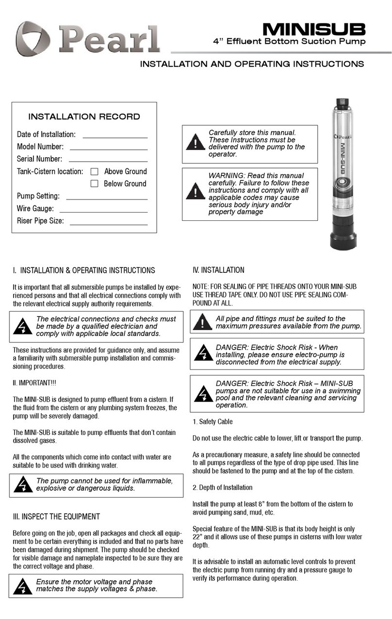
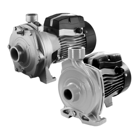
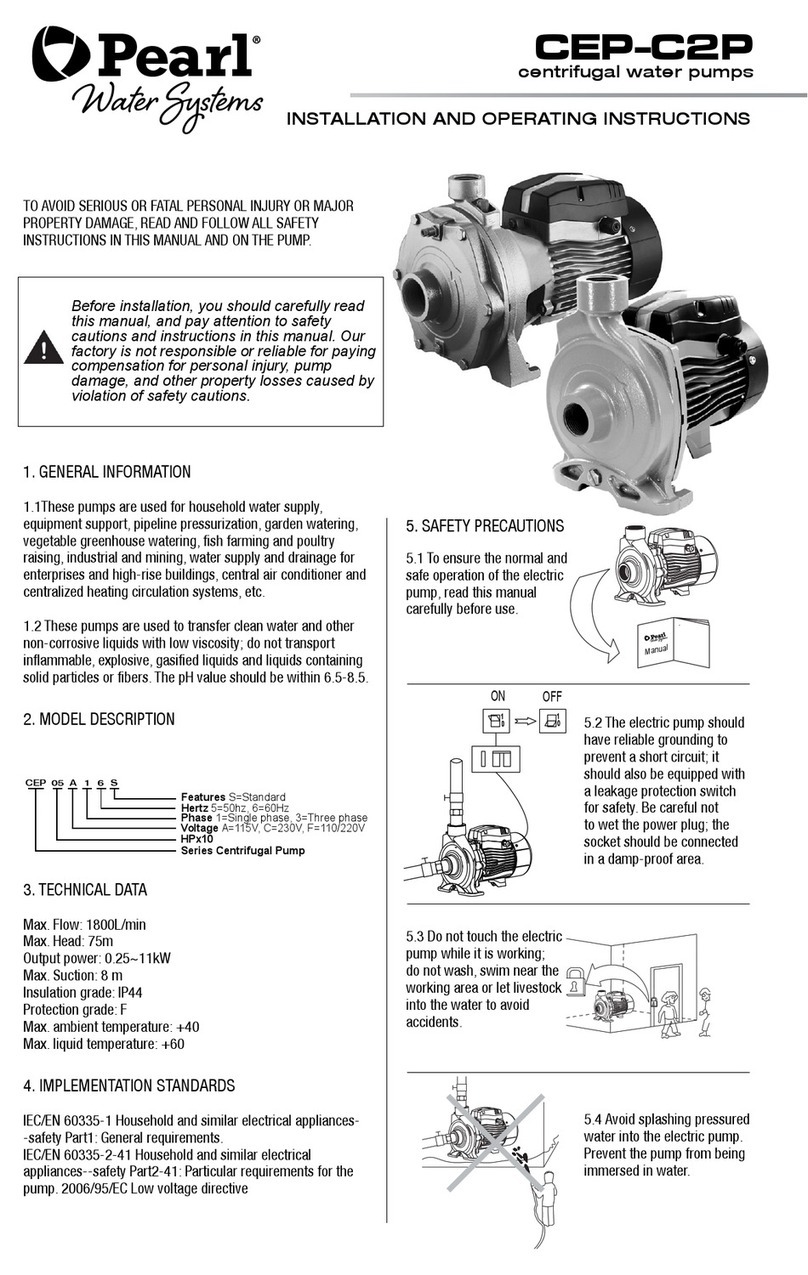
Pearl CEP BIG User manual

centrifugal pumps
CEP BIG
INSTALLATION AND OPERATING INSTRUCTIONS
TO AVOID SERIOUS OR FATAL PERSONAL INJURY OR MAJOR
PROPERTY DAMAGE, READ AND FOLLOW ALL SAFETY
INSTRUCTIONS IN MANUAL AND ON PUMP.
Before installing and using the pump, read the
following instructions carefully.
The manufacturer declines all responsibility in case
of accident or damage due to negligence or lack of
observance of the instructions described in this booklet
or in conditions that differ from those indicated on the
nameplate; it also declines all responsibility for damage
caused by improper use of the pump.
1. APPLICATIONS
1.1. CEP BIG standard pumps are qualified to handle clean
water or liquids similar to water in physical and chemical
properties. The PH value of the transmission liquids shall be
between 6.5 and 8.5.
1.2. It is widely used for farm irrigation and drainage in facto-
ries, mines, schools, hospitals, hotels and cities. It can also be
used as circulation pump for central air-conditioning and central
heating system. With impeller of welding stainless steel or
casting copper, it can be used as pumps for fire fighting system
and spraying system.
2. MODEL DESCRIPTION
3. TECHNICAL DATA
Flow rate: 0 - 60 m3/h
Head: 25 - 105 m
Speed: 3500 rpm
Insulation class: F
Protection class: IP54(4-7.5kW), IP55(11-15kW)
Max. operating pressure: 10 bar
Max. ambient temperature: +40°C
Max. liquid temperature: +75°C
4. IMPLEMENTATION STANDARDS
- 73/23/CEE
- 89/392/CEE
- 89/336/CEE
- Mechanical seal in compliance with DIN 24960
- Inlet and outlet DN in compliance with EN 733 and UNI 7467
5.1. To ensure normal and
safety operation of the
electric pump, read manual
carefuly before use.
5.2. To avoid electric shock,
make sure that the pump is
safely grounded and equipped
with an earth leakage
circuit breaker. Do not get the
plug wet and do not use any
socket in an area with high
humidity.
5.3. Do not touch the
electric pump while work-
ing; do not wash or swim
near the working area or
let livestock into the water
to avoid accident.
5.4. Avoid splashing pres-
sured water to the electric
pump.
Standard
Hz
Phase
Voltage
Rated Hp x 10
Close Coupled End Suction Centrifugal Pump
CEP 50 H 3 6 S
Manual
5. SAFETY PRECAUTIONS

7. INSTALLATION
6. PRODUCT STRUCTURE
PRODUCT STRUCTURE cont...
POS. PART
1 Pump body
2 Impeller
3 O-sealing ring
4 Motor connector
5 Motor
6 Terminal box
7 Coupling
8 Mechanical seal
9 Keys
POS. PART
1 Pump cover
2 Impeller
3 O-sealing ring
4 O-sealing ring
5 Pump body
6 Mechanical seal
7 Water proof ring
8 Bracket
9 Fan
5.5. Make sure the pump is
installed in a well-aired place.
5.6. Before carrying out
checks or doing any main-
tenance,
clear the system by
disconnecting the voltage,
and then remove the pump
plug from the socket.
5.7. Ensure the pump will not
be accidently turned on
while installing and
maintaining; if not used
for a long time, cut off the
power first and then turn off
valves in inlet and outlet of
the pump.
5.8. The pump must operate
with clean water. It is not
suitable for pumping
inflammable, gasified or
explosive liquids.
5.9. The power supply shall
be in accordance with the
voltage stated on the
nameplate.
4℃
1 2 3 4
56
7
8
9
1 2 3 4 5 6 7 8 9 10
11
12
13
14
1 2 3 4
56
7
8
9
1 2 3 4 5 6 7 8 9 10
11
12
13
14
DNM B
h1 h2
h
aw
L
DNA
m1
s
n
n1
m
DNM
DNA
a
L
B
h1 h2
h
m1
m
b
s
n
n1
b
MODEL DNM DNA a h2 w x b c h1 m m1 n n1 s B Hmax L
CEP 50
50 50
70 210 258 127 50 12 136 100 70 240 190 14 255 346 450
CEP 75
137 210 263 180 60 15 160 22 70 272 212 14 308 370
570
CEP 100 591
CEP 150
93 252 309 245 65 20 160 260 210 314 254 15 322 412 787
CEP 200
8. PERFORMANCE DATA
MODEL speed
(r/min) Rated flow
(m3/h) Rated flow
(m) Power
(kW)
CEP 50
3500
24 38 4
CEP 75 16 61 5.5
CEP 100 19 75 7.5
CEP 150 31 60 11
CEP 200 35 70 15

9. PRIOR TU USE
During installation apply all the safety regulations
issued by thecompetent authorities and dictated by
common sense.
9.1.With the appropriate bolts secure the pump to flat and solid
surfaces toavoid vibrations. The resistance of the motor shall be
more than 50MΩ.
9.2. Before startup, check if the pump turns freely by rotating
the fan. Remove the filling plug and fully fill the pump chamber
with clean water, then tighten the filling plug.
9.3. In case the electric pump is far from the power supply, it’s
necessary to use a thicker cable. Otherwise the pump cannot
work properly due to the big voltage drop.
9.4. Do not use soft rubber tube for inlet pipeline during
installation. A foot valve shall be vertically installed with a
distance of at least 30 cm from the water bottom to avoid
suction of sediment.
9.5. Pay attention to the water level during operation. The foot
valve shall not be above the water surface.
9.6. If the pump is not be used for a long time, it is advisable to
empty it completely, wash it with clean water and store it in a
dry, well-ventilated
place.
This product shall be installed and maintained by a
qualied person who is procient with this instruction.
The installation and operation must be in accordance
with local regulations and the recognized operation
criteria. Install the pipeline properly according to the
requirement of this instruction, and protect it from
freezing.
CORRECT INSTALLATION
A DIAGRAM
CORRECT INSTALLATION
B DIAGRAM
1. Discharge plug
2. Electric pump
3. Outlet pipeline
4. Joint
5. Filling plug
6. Inlet pipeline
7. Foot valve
8. Support
NOTES FOR INLET PIPELINE INSTALLATION:
1. Do not use too soft rubber tube for the inlet pipeline during
pump installation.
2. The foot valve should be vertically installed 30cm from water
bottom to avoid suction of sediment (A)
3. All connections of the inlet pipelines must be sealed.
To ensure water suction, it’s necessary to reduce the quantity
of bents of the pipelines.
4. The diameter of the inlet pipe must not be less than that of
the pump inlet to avoid big hydraulic loss and small water flow.
5. Pay attention to the water level during operation. The foot
valve shall not be above the water surface (B).
6. In case the inlet pipe is longer than 10m in length or over 4m
in hoisting height, the pipe diameter should exceed diameter of
water inlet of the pump.
7. The pipelines should be anchored so that no stresses
whatsoever is transmitted to the pump.
8. It is recommended to install a filter on inlet pipeline to avoid
incoming of solid particles to the electric pump.
NOTE FOR OUTLET PIPELINE INSTALLATION:
The diameter of the outlet pipeline shall be not less than that of
the pump outlet to reduce the pressure drop, high flow rate and
noise to the lowest level.
10. ELECTRICAL CONNECTIONS
Make sure that there is no voltage at the line wire
terminals before connecting.
The electric pump shall be grounded reliably to avoid
electric leakage and an earth leakage circuit breaker
shall be equipped.
The electrical connection shall be carried out according to the
local regulations.
Check that the pump operates within the specied range on the
nameplate.
Connect up the pump (making sure that there is an efcient
grounding circuit) according to the diagram on the nameplate on
the motor.
The correct direction of rotation for three-phase motors is
clockwise, looking at the pump from the motor fan side. If this is
not the case, invert two of the phases.
switch
fuse
pressure
switch
magnetic
thermal
switch
switch
fuse
pressure
switch
magnetic
thermal
switch
Direct ConnectionY /
Connection
L
1
L
2
L
3
M
3~
M
3~
L
1
L
2
L
3
M
3~
M
3~
L
1
L
2
L
3
L
1
L
2
L
3
T
1
T
2
T
3
T
1
T
2
T
3

DIRECT CONNECTION Y
11. STARTUP AND MAINTENANCE
Do not operate the pump unless the pump chamber is
fully lled with clean water.
Dry operation of the pump will cause damage to the
mechanical seal.
Do not touch the electric pump unless the power of
pump is cut off for over 5 minutes.
Do not remove the pump bonnet unless the water in
pump chamber is completely drained.
Rotate the fan with a screwdriver to check if the pump rotates
flexibly before startup. Remove the filling plug and prime the
pump chamber fully with clean water, then tighten the filling
plug.
PROBLEM POSSIBLE CAUSE SOLUTION
The pump
does not
start
Low voltage Regulate voltage variation between +/-10%
Impeller blocked Clean the impeller by removing it
Cable broke or one phase disconnected Check out outlet box and replace the cable
Stator winding burnout Replace the stator winding
Insufficient
liquids
pumped
Excessive head Choose appropriate standard pump according to the scope
of application
Foot valve clogged or filter screen blocked Clean up the float grass
Suction pipe leakage Tighten the adaptor of suction pipe evenly
Mechanical seal damage Replace mechanical seal
Stator
winding
burnout
Wrong grounded circuit or phase failure of power
Fix the problems by removing the winding, re-embedding,
the winding, re-embedding, drying it by heat.
Seal box broken and the coil burns out
Long time of dry operation
Impeller blocked or long-time running
Cable broke and winding exposed to moisture
12.TROUBLESHOOTING
3000 W. 16 Ave. Miami, FL 33012
Tel: (954) 4749090 | Fax: (954) 8890413
Keep the valve narrow opened during startup. When the pump
runs normally, adjust the valve to the required flow.
When not using the pump and the ambient temperature is
below 4, empty the pump completely for frost and freeze
protection. The priming procedure must be repeated to restart
the pump.
Attention! If the appliance or the supply cord is
damaged, it must be repaired by manufacturer, its
service agent or qualied person.
CONNECTION
L1 L2 L3
GY
PE
WE
BK
PK
CE
BE YW RD
W2 U2 V2
U1 V1 W1
440~480V
L1 L2 L3
PK GY
BK
WE
CE
LB Y W R D
PE
W2 U2 V2
U1 V1 W1
2
220~240V
L1 L2 L3
GY
PE
WE
BK
PK
CE
LB Y W R D
W2 U2 V2
U1 V1 W1
440~480V
L1 L2 L3
PK
GY
BK
WE
CE
BE Y W RD
PE
W2 U2 V2
U1 V1 W1
2220~240V
BK
CE
WE
RD
YW
GY
PE
PK
BE
- black
- coffee
- white
- red
- yellow
- grey
- purple
- pink
- blue
BK
CE
WE
RD
YW
GY
PE
PK
BE
- black
- coffee
- white
- red
- yellow
- grey
- purple
- pink
- blue
BK
CE
WE
RD
YW
GY
PE
PK
BE
- black
- coffee
- white
- red
- yellow
- grey
- purple
- pink
- light blue
BK
CE
WE
RD
YW
GY
PE
PK
BE
- black
- coffee
- white
- red
- yellow
- grey
- purple
- pink
- light blue
L1 L2 L3
GY
PE
WE
BK
PK
CE
BE YW RD
W2 U2 V2
U1 V1 W1
440~480V
L1 L2 L3
PK GY
BK
WE
CE
LB Y W R D
PE
W2 U2 V2
U1 V1 W1
2
220~240V
L1 L2 L3
GY
PE
WE
BK
PK
CE
LB Y W R D
W2 U2 V2
U1 V1 W1
440~480V
L1 L2 L3
PK
GY
BK
WE
CE
BE Y W RD
PE
W2 U2 V2
U1 V1 W1
2220~240V
BK
CE
WE
RD
YW
GY
PE
PK
BE
- black
- coffee
- white
- red
- yellow
- grey
- purple
- pink
- blue
BK
CE
WE
RD
YW
GY
PE
PK
BE
- black
- coffee
- white
- red
- yellow
- grey
- purple
- pink
- blue
BK
CE
WE
RD
YW
GY
PE
PK
BE
- black
- coffee
- white
- red
- yellow
- grey
- purple
- pink
- light blue
BK
CE
WE
RD
YW
GY
PE
PK
BE
- black
- coffee
- white
- red
- yellow
- grey
- purple
- pink
- light blue
Other Pearl Water Pump manuals
Pearl
Pearl CQPL User manual

Pearl
Pearl Iron Jet IRONJ 05 User manual
Pearl
Pearl CQPL Series User manual
Pearl
Pearl JACKY User manual
Pearl
Pearl CSP User manual
Pearl
Pearl VPS 1 User manual
Pearl
Pearl JCP User manual

Pearl
Pearl JCCH Series User manual
Pearl
Pearl 4MWP Series User manual

Pearl
Pearl MXA Series User manual
Popular Water Pump manuals by other brands

Black & Decker
Black & Decker BXGP800XE Original instructions

Graco
Graco Husky 3300 repair parts

APEC PUMP
APEC PUMP ST Series Installation and operation manual
Pentair
Pentair Myers SHA Series Installation and service manual
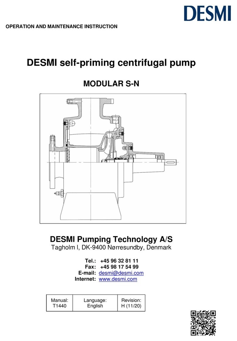
Desmi
Desmi Modular S-N Series Operation and maintenance instruction

Xylem
Xylem Goulds SHV Series Installation, operation and maintenance instructions

