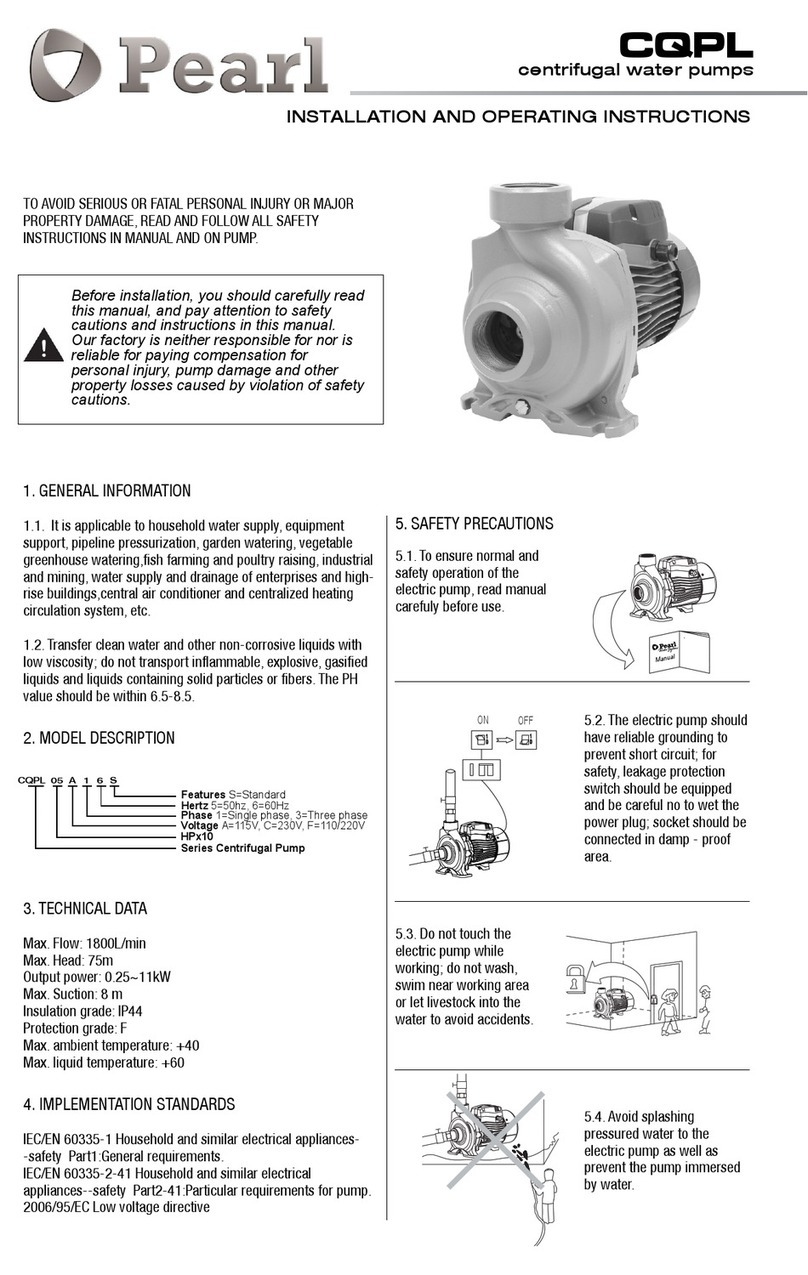
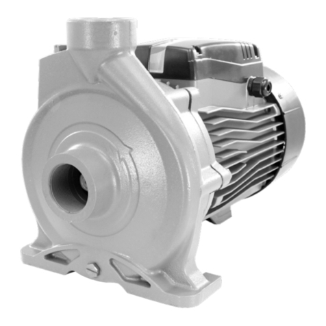
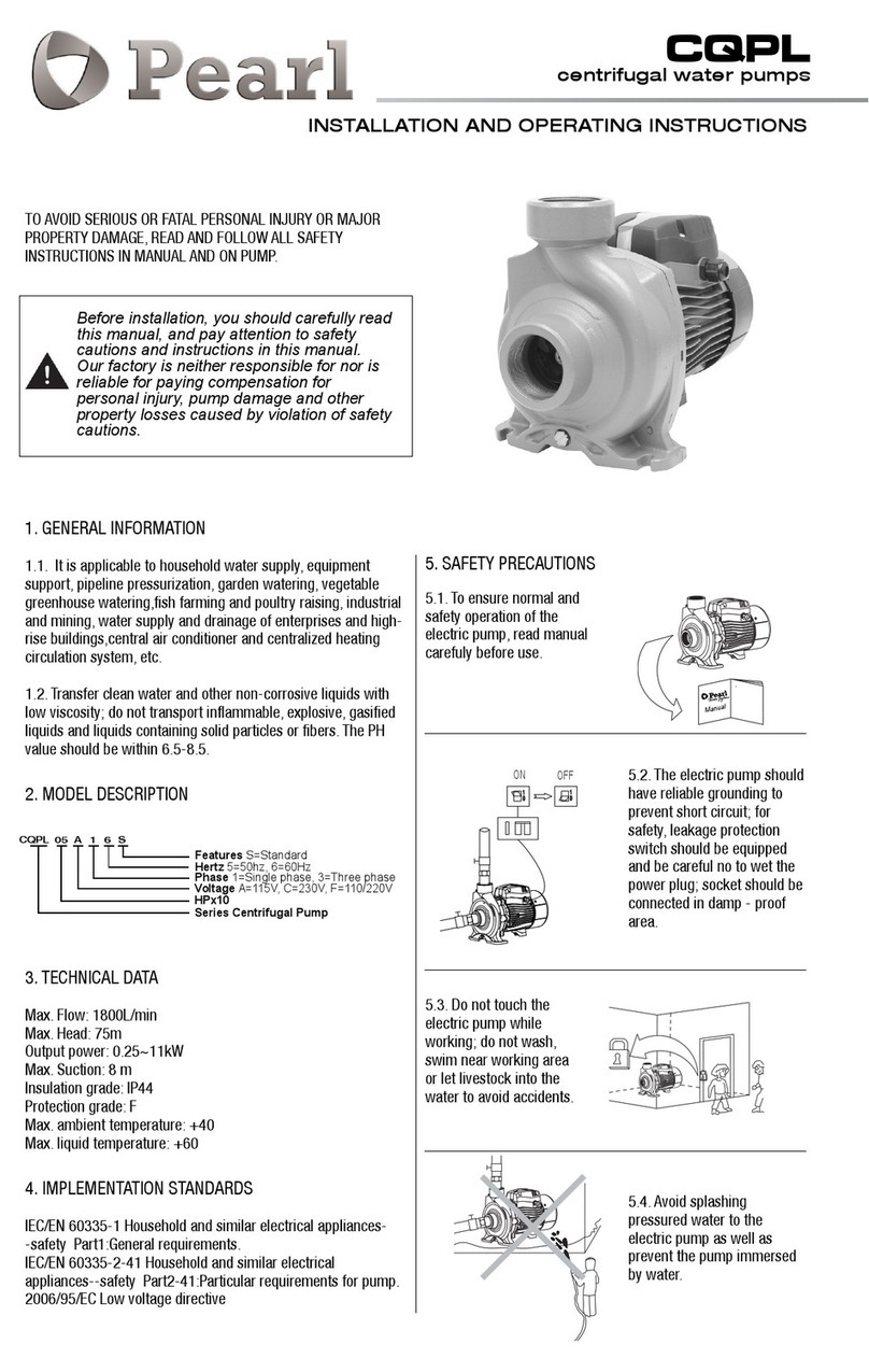
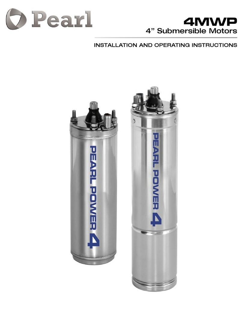
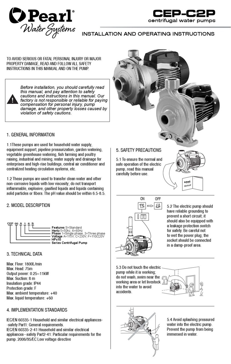
Pearl CEP-C2P User manual

centrifugal pumps
CEP-C2P
INSTALLATION AND OPERATING INSTRUCTIONS
TO AVOID SERIOUS OR FATAL PERSONAL INJURY OR MAJOR
PROPERTY DAMAGE, READ AND FOLLOW ALL SAFETY
INSTRUCTIONS IN MANUAL AND ON PUMP.
Before installation, you should carefully read
this manual, and pay attention to safety
cautions and instructions in this manual.
Our factory is neither responsible for nor is
reliable for paying compensation for
personal injury, pump damage and other
property losses caused by violation of safety
cautions.
1. GENERAL INFORMATION
1.1. It is applicable to household water supply, equipment
support, pipeline pressurization, garden watering, vegetable
greenhouse watering,fish farming and poultry raising, industrial
and mining, water supply and drainage of enterprises and high-
rise buildings,central air conditioner and centralized heating
circulation system, etc.
1.2. Transfer clean water and other non-corrosive liquids with
low viscosity; do not transport inflammable, explosive, gasified
liquids and liquids containing solid particles or fibers. The PH
value should be within 6.5-8.5.
2. MODEL DESCRIPTION
3. TECHNICAL DATA
Max. Flow: 1800L/min
Max. Head: 75m
Output power: 0.25~11kW
Max. Suction: 8 m
Insulation grade: IP44
Protection grade: F
Max. ambient temperature: +40
Max. liquid temperature: +60
4. IMPLEMENTATION STANDARDS
IEC/EN 60335-1 Household and similar electrical appliances-
-safety Part1:General requirements.
IEC/EN 60335-2-41 Household and similar electrical
appliances--safety Part2-41:Particular requirements for pump.
2006/95/EC Low voltage directive
Hertz 5=50hz, 6=60Hz
Features S=Standard
Series Centrifugal Pump
Phase 1=Single phase, 3=Three phase
Voltage A=115V, C=230V, F=110/220V
HPx10
ON
OFF
11
00
00
11
5.1. To ensure normal and
safety operation of the
electric pump, read manual
carefuly before use.
5.2. The electric pump should
have reliable grounding to
prevent short circuit; for
safety, leakage protection
switch should be equipped
and be careful no to wet the
power plug; socket should be
connected in damp - proof
area.
5.3. Do not touch the
electric pump while
working; do not wash,
swim near working area
or let livestock into the
water to avoid accidents.
5.4. Avoid splashing
pressured water to the
electric pump as well as
prevent the pump immersed
by water.
Manual
CEP 05 A 1 6 S
5. SAFETY PRECAUTIONS

123
5
6
8
9
10
11
12
13
4
7
14
15
16
17
18
6. PRODUCT STRUCTURE
POS. PART
1 Pump body
2 Impeller
3 Mechanical seal
4 Seal holder
5 Motor support
6 Bearing
7 Rotor
8 Spring washer
9 Fan cover
7. PIPELINE INSTALLATION
This product should be installed and
maintained by personnel who is procient in
this manual and has special qualications.
Installation and operation should be in
accordance with local regulations and
recognized operation standards.
Install pipelines properly as stipulated in the
manual and eanwhile conduct frost protection
measures for the pipeline.
7.1 For pump installation, the inlet pipe should be as short as
possible with the least turnings.The pump should be installed
in ventilated and dry environment. It could be installed outside,
provided having proper covering to prevent rain and wind.
7.2 For pipeline use, valves should be installed on inlet and
outlet pipelines and the inlet pipeline should be installed with
check valve.
10 Fan
11 End plate
12 Cable holder
13 Capacitor
14 Capacitor box
15 Terminal board
16 Stator
17 Bracket
18 O-sealing ring
5.5. Keep the pump in
ventilation.
5.6. In case ambient tempera-
ture is lower than 4 or the
pump is not used for a long
time, empty liquid the pipeline
system to avoid ice cracking
of the pump chamber. Do not
operate the pump for a long
time without water in it.
5.7. The pumped liquid
maybe hot and under high
pressure, before moving and
demounting the bump, valves
in both sides of the bump
should be turned off first and
then empty liquids in the
pump and pipelines so as not
to be scalded.
5.8. Do not transfer any
inflammable, explosive or
gasified liquids that beyond
the stipulation.
5.9. Ensure the pump will not
be accidently turned on while
installing and maintaining; if
not used for a long time, cut
off the power first and then
turn off valves in inlet and
outlet of the pump.
5.10. Power supply should be
in accordance with the
voltage stated in the
nameplate. If not used for a
long time, put the pump in
dry, ventilated and cool place
under room temperature.
Max. water temperature: + 60
Min. Water temperature: +4

NEGATIVE SUCTION
CORRECT INSTALLATION
INCORRECT INSTALATION
POSITIVE SUCTION
CORRECT INSTALLATION
INCORRECT INSTALLATION
1. Foot valve
2. Inlet pipe
3. Tie-in
4. Filling plug
5. Drain plug
6. Electric pump
7. Valve
1
2
3
4
5
6
7
3
INSTALLATION PRECAUTIONS FOR INLET PIPELINES
1. While installing the electric pump, do not use too soft rubber
tube for the inlet pipeline, avoiding to be sucked flat.
2. The foot valve should be vertically placed and installed 30 cm
from water bottom to avoid sucking in sands and stones (B2);
3. Joints of the inlet pipelines should be sealed with the least
elbows, no water can be sucked.
4. Diameter of the inlet pipe should be at least in accordance
with that of the water inlet, so as to avoid too much water loss
which will influence outlet performance.
5. Pay attention to drop of water level while using, the foot valve
should not be above the water surface (B1).
6. In case the inlet pipe is longer than 10m or its lifting height
exceeds 4m, the pipe diameter should exceed diameter of water
inlet of the pump.
7. Ensure the pumped will not be affected by pipeline pressures
while installing the pipelines.
8. Filter should be installed in inlet pipelines so as to avoid solid
particles to enter into the electric pump.
INSTALLATION PRECAUTIONS OF THE OUTLET PIPELINE
1. Pipe diameter of the outlet pipeline should be at least in
accordance with that of the water outlet, so as to reduce its
voltage drop, high flow rate and noise to the minimum.
2. Verify valve check is installed in the correct way.
8. ELECTRICAL CONNECTION
Unless the power is o, do not wiring the
junction box. The electric pump should
have reliable grounding to prevent current
leakage with leakage protection switch being
equipped.
8.1 Electrical connection and protection should be conducted
according to stipulations. Specification of working voltage is
marked on the nameplate; please ensure the motor is in
accordance with power supply.
8.2 In case the working area of the electric pump is too far
from the power supply, power transmission lines should be
of a heavier gauge, otherwise the electric pump cannot work
normally because the voltage drop is too dramatic.
8.3 In case the electric pump is used outdoor, extended lines
should apply rubber cables for outdoor use.
8.4 Check rotation of the motor (three-phase motor)
8.5 Check whether operation of the electric pump is normal,
rotation is correct, which could be observed from the fan blade
terminal, e.g. clockwise rotation means correct direction. In
case the rotation is incorrect, cut off power and exchange the
two power leads.
B1 B2
1. Waterpump
2. Drain plug
3. Tie-in
4. Check valve
5. Valve
6. Inlet pipe
7. Basket
8. Filling plug

9. START-UP MAINTENANCE
Do not start up the pump before the pump
chamber is lled with water.
Do not touch the electric pump unless its
power has been cut o for at least 5 minutes.
Do not dismount the pump body unless
water in the pump chamber is empted.
9.1 Rotate the fan blade before start-up, check whether the
pump rotation is flexible and then unscrew the water-filling
plug, fill the pump chamber with clean water from the water
injection hole, then tighten the plug screw after gas has been
completely discharged.
The valve should be shut tightly while starting up the pump.
After the pump discharges water and operates normally, adjust
the valve to the required flow (flow and lift will be displayed on
the nameplate).
ATTENTION:
1) In case no water is discharged after being started for more
than 5 minutes with water filled, turn off the electric pump,
re-fill water or check whether the inlet pipeline has leakages.
2) In case of any frost and ice damages, please open the drain
plug to empty water in the pump chamber. When start up the
pump again, open the drain plug, fill water and tighten it and
then the pump is usable.
3) In case not use for a long time, water in the pump should
be emptied. The pump body, impeller and support should be
cleaned and coated with anticorrosive oil before they are put in
a ventilated and dry place for use.
4) In case the pump is halted for a long time, start it up again
according to above diagram.
5) In summer or when the ambient temperature is high, pay
attention to ventilation, avoid dew on electrical parts which will
result in electrical faults.
6) In case the motor is hot or abnormal, cut off the power
immediately and check faults according to the following table.
Earth /tierra
L2
L1
CAPACITOR
110V 220V
SINGLE PHASE CONNECTION 110V or 220V
SINGLE PHASE CONNECTION 110/220V, 60 Hz
VOLTAGE SELECTOR
THREE PHASE CONNECTION
Y
L3
L2
L1
L3
L1
L2

3000 W. 16 Ave. Miami, FL 33012
Tel: (954) 4749090 | Fax: (954) 8890413
PROBLEM POSSIBLE CAUSE REMEDY
MOTOR DOES NOT START OR
RUN
Single-phase power supply (three-phase electric
motor):
a. poor connection of the power switch;
b. fuse is burned out;
c. loose power lead;
d. phase failure of the cable
a. repair switch contact or replace the switch;
b. replace the safety fuse;
c. check and tighten the power connector;
d. repair or replace cables
Capacitor is burned out Replace with a same type capacitor (send to the
maintenance point for repair)
The rotating shaft and bearing are jammed. Replace the bearing (send to the maintenance point for
repair)
Impeller is jammed.
Turn rotating shaft of the fan blade terminal with screw
driver to let it rotate flexibly or demount the pump body to
clear sundries.
Stator winding is damaged Replace winding coils (send to the maintenance point
for repair)
THE MOTOR IS IN OPERATION,
BUT NO WATER IS DIS-
CHARGED
Incorrect direction of pump rotation Invert two-phase wirings of the motor (three-phase motor)
The pump is not fully filled with water Re-fill the pump with water.
The impeller is damaged Replace the impeller (send to the maintenance point for
repair)
Leakage of the suction pipe Check sealing of various joints of the inlet pipelines
Water level is too low Adjust installation height of the pump
Freeze caused by accumulated water in the pipeline
or the chamber Start up the pump after ice is melted
INSUFFICIENT PRESSURE
Incorrect pump type Select suitable pump
The inlet pipeline is too long or with too many
bends, pipe diameter is not selected as required.
Apply the pipe with the stipulated diameter, and make the
inlet pipe short.
Inlet pipeline, filter screen or pump chamber is
blocked by foreign materials Clean pipeline, foot valve or pump chamber, clear sundries
MOTOR WORKS INTERMIT-
TENTLY OR THE STATOR
WINDING IS BURNED OUT
The impeller is jammed or overload operation for
a long time
Clear sundries in the pump chamber; operate the pump
under the rated flow as much as possible.
Incorrect grounding, broken cable or the electric
pump is hit by lightning. Seek for the reason, and replace winding coils.
LEAKAGE OF MECHANICAL
SEAL
The mechanical seal is worn and torn by
impurities. Clear or replace the mechanical seal
ABNORMAL NOISE FROM
THE PUMP
Noise from the bearing Replace with the same type bearing
Impeller is jammed. Remove sundries
Excessive flow Adjust to the range displayed on the nameplate before use.
10.TROUBLESHOOTING
Other manuals for CEP-C2P
1
Table of contents
Other Pearl Water Pump manuals
Popular Water Pump manuals by other brands

Ingersoll-Rand
Ingersoll-Rand PD20R-X-XCX Series Operator's manual

Toyotomi
Toyotomi OPT-91UL Installation & operation instructions

Garland
Garland GEISER 801 QG instruction manual

Parker
Parker F12 series Service manual

MULTIQUIP
MULTIQUIP MG30T2D Operation manual

SMITH & LOVELESS
SMITH & LOVELESS Sonic Start Streamline Installation & operation instructions