Frame Construction Ceiling Installation
1
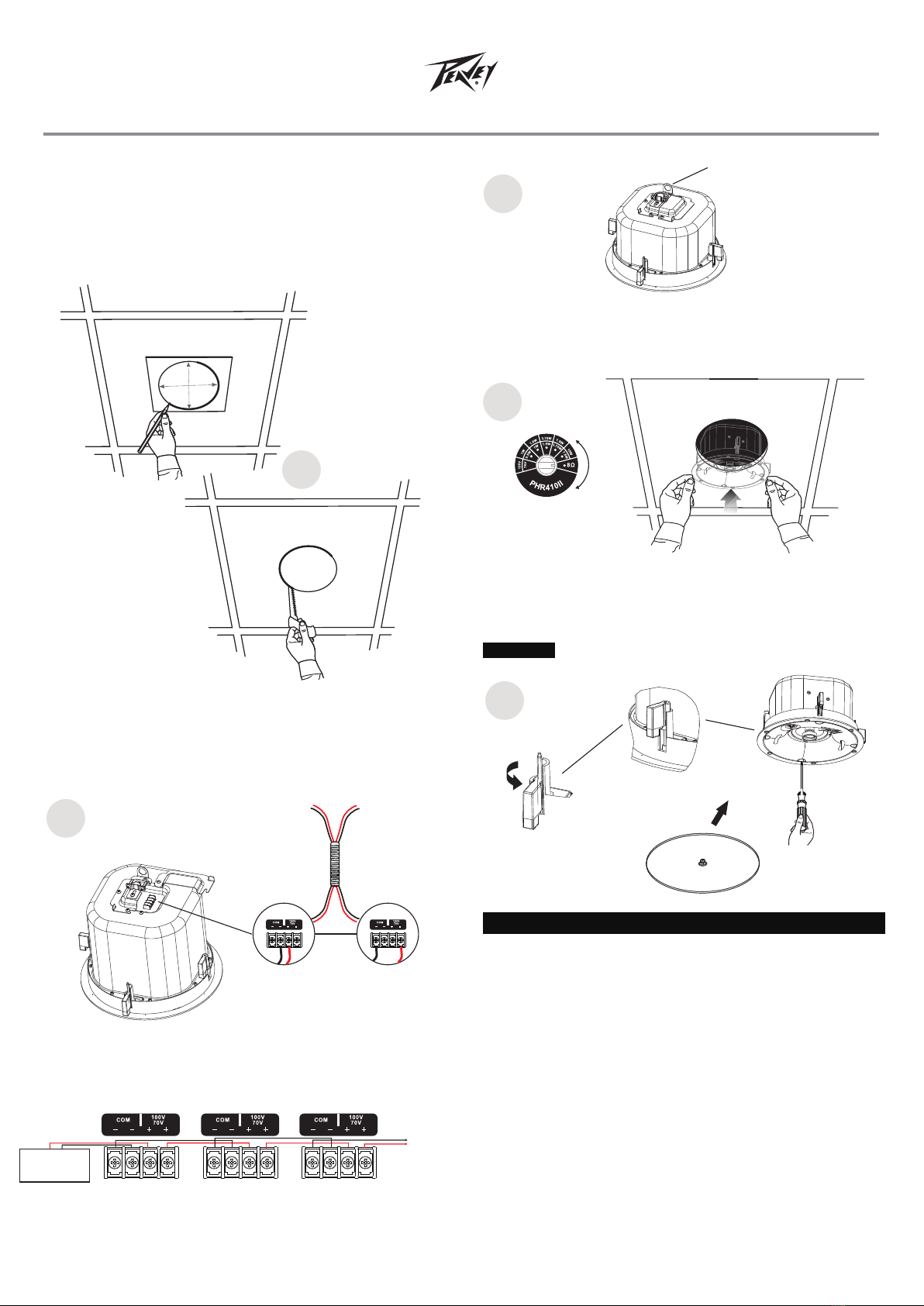
Take the cutout template from the packaging box and punch out
along the larger perforated circle. Place the cutout template
against the bottom of the ceiling and trace the inside of it.
Carefully cut out the ceiling material along the circle.
9.56"
243mm
2
Remove the top cover to contact the 4-position screw-terminal
barrier strip on the back of the speaker. Connect the speaker
wire to the 4-position screw-terminal barrier strip . Install the
catheter and secure the connection.
1
PHR410II
Ceiling Speaker
Frequency Response ..............65Hz - 11.8kHz,-10dB
Power Handling ............... 40W @8Ω......
Nominal Sensitivity.............. 86dB ±3dB ,1m,1W..
Transformer Taps.............. 15W, 7.5W, 3.75W, 1.9W, 1W, (100V)......
70V capable
Component 4" woofer, PP cone .............................. and rubber
surround 3/4" soft dome tweeter
Crossover Frequency 4kHz..............
Outside Dimensions 275mm x 170mm...............
Cutout Diameter 243mm.....................
Weight 1 81kg/4 lbs...................................... .
PEAVEY PHR410II Ceiling Speaker Specifications
2
Replace the top cover and tighten the screws. connector a
dary support line from the seismic tab to a secure support point.
secon-
3
Parallel Hookup Wiring Diagram
ꜜCover
ꜜ
To speaker
ꜜ
From
Power Amplifier
Enlarged to
Show Detail
5
5
Loosen the four screws on the front baffle (counter clockwise)
1/2 turn. Then tighten the screws (clockwise) until the dog legs
clamp the speaker to the ceiling. Then install the speaker grille.
Do not over tighten screws.CAUTION
Adjusting the tap selector
4
Remove the grille and set the rotary tap selector switch.
the speaker through the bottom of the hole in the ceiling.
insert
Support
Line
power
amplifier
-
+
To speakers
Speaker1 Speaker2 Speaker3
LOOP
THRU
IN
IN LOOP
THRU
LOOP
IN
IN LOOP LOOP
IN
IN LOOP
2
3
4
Recommended filter type and point: 24 dB/oct.
Linkwitz-Riley at 80 Hz.


