Peco PRO 2 BAGGER User manual

OPERATOR’S MANUAL
GRASS COLLECTION
SYSTEM
ASSEMBLY OPERATION MAINTENANCE
MANUAL PART#: Q0376 REV: 3
P
PECOPECO
PPPP
PECOPECOPECO
PRO 2 BAGGER
DESIGNED FOR:
THE JAZEE & JAZEE PRO
AND THE WRANGLER

RESIDENTIAL BAGGING SYSTEM
TABLE OF CONTENTS
1.
2.
3.
4.
5.
6.
7.
8.
9.
10.
11.
12.
13.
Read the operator’s manual carefully and familiarize yourself with the proper use of your attachment. Do
not allow anyone who is not acquainted with the Safety Instructions to use your attachment.
Know the controls and how to stop quickly. READ THE OPERATOR’S MANUAL!
Do not allow children to operate the mower. Do not allow adults to operate the mower or grass collection
system without proper instruction.
Be especially watchful of children and pets darting into the area while operating.
Keep your eyes and mind on your unit while mowing or operating your attachment. Don’t let others
distract you.
Do not attempt to operate your unit or mower when not in the driver’s seat.
Always stop unit when emptying the container.
Stop unit, shut off deck attachment, set parking brake, shut off mower engine and remove spark plug wire
before removing clogs, removing or replacing hose, boot, blower cone, or performing any maintenance.
If a slope must be ascended, back up the slope; drive forward when descending.
It is recommended that the container be kept only half full when negotiating any slopes. Start mowing on
slopes when the container is empty and never mow slopes greater than 15 degrees.
Inspect your lawn and remove any foreign objects before mowing. Never deliberately run the mower
across any foreign object.
Wear ear protection if the noise level is offensive.
Wear eye protection to prevent debris from damaging your eyes.
SECTION PAGE
Safety ------------------------------2
Safety Alert Symbols----------------------3
Warranty -----------------------------4
I INTRODUCTION AND DESCRIPTION - - ------------5
1-1 Introduction - ------------------------5
1-2 Description - ------------------------5
II INSTALLATION FOR USE ----------------------5
2-1 Preparation Of Mower ------------------5
2-2 Removing The Rear Panel Guard
and The Muffler Guard ------------------6
2-3 Right Frame Mount Assembly Installation------6
2-4 Left Frame Bracket Installation- ------------6
2-5 Lower Frame Assembly Installation----------6
2-6 PTO Assembly Installation - - - ------------7
2-8 Exhaust Deflector Installation - ------------8
2-9 Upper Frame Assembly Installation
2-10 Top Assembly To Upper Frame
Assembly Installation ------------------8
2-11 Blower Cone Installation/Removal ----------9
2-7 Belt Installation/Removal/Adjustment - - - - - - - 7-8
SECTION PAGE
2-12 Impeller Blade Removal/Replacement - ------9
2-13 Boot To Mower Deck Installation ------ - - - -9-10
2-14 Length of Hose Adjustment - - ------------10
Exploded Views And Parts List - - - ------- - - - 15-21
2-15 Upper Hose Installation ----------------10
2-16 Lower Hose To Blower Cone Installation------10
2-17 Lower Hose To Boot Installation -----------11
2-18 Front Weight Installation ----------------11
2-19 Installation/Removal Of Collection Bags ------12
III OPERATING INSTRUCTIONS - ------------------13
3-1 General Safety -----------------------13
3-2 Operation & Tips On Mowing - - ------------13
3-3 Disengagement Of The PTO Assembly - ------13
3-4 Unloading The Collection System -----------13
IV MAINTENANCE----------------------------13
4-1 Maintenance Checklist ------------- - - - --13
4-2 Lubrication- - ------------------------14
V PARTS AND SERVICE -----------------------14
5-1 Parts And Service Information - ------------14
Safety Decals - - ------------------------22
Torque Specifications - - - ------------------23
2
SAFETY

3
SAFETY
WARNING!
WARNING!
WARNING!
WARNING!
Safety Alert Symbol
Safety Signs
NEVER
ONLY AFTER
STOPPING THE MOWER’S ENGINE AND WAITING FOR ALL MOVING PARTS TO COME TO A
COMPLETE STOP.
ALWAYS NEVER
ATTENTION! BECOME
ALERT! YOUR SAFETY IS INVOLVED!”
DANGER, WARNING, AUTION
operate the mower unless the discharge guard and either the deflector assembly or the
vacuum collector adapter are fastened securely in place.
Do not work around the mower deck boot or the blower area until you are certain that the mower
blades and the blower impeller have stopped rotating.
To avoid serious injury, perform maintenance on the vacuum collector;
Set the parking brake. Always remove the ignition key before beginning maintenance.
For your own personal safety, back up the face of slopes. attempt to mow
excessively steep slopes, and use caution when turning on any slope.
This Safety Alert Symbol means:
This symbol is used to call attention to safety precautions that
should be followed by the operator to avoid accidents. When
you see this symbol, carefully read the message that follows
and heed its advice. Failure to comply with safety precautions
could result in death or serious bodily injury.
The signal words and are used on the equipment safety signs. These words are
intended to alert the viewer to the existence and the degree of hazard seriousness.
“
C
!
DANGER
!
WARNING
!
CAUTION
!
This signal word indicates a potentially hazardous situation which, if not
avoided, will result in death or serious injury.
This signal word indicates a potentially hazardous situation which, if not
avoided, could result in death or serious injury.
It may also be used to alert against unsafe practices.
This signal word indicates a potentially hazardous situation exist which, if
not avoided, will result in minor or moderate injury.
It may also be used to alert against unsafe practices.
White letters on RED
Black letters on ORANGE
Black letters on YELLOW

COUNTRY CLIPPER LIMITED WARRANTY FOR NEW PRODUCTS
A. WHAT IS WARRANTED?
1. PRODUCT WARRANTY:
ALL DEFECTIVE PARTS MUST BE RETURNED TO COUNTRY
CLIPPER FOR INSPECTION TO DETERMINE VALIDITY OF WARRANTY CLAIMS.
2. PARTS REPLACED DURING WARRANTY:
B. SECURING WARRANTY ADJUSTMENTS.
C. ITEMS NOT COVERED BY COUNTRY CLIPPER WARRANTY.
D. UNAPPROVED ALTERATION OR MODIFICATION.
E. ACCIDENTS AND NORMAL MAINTENANCE.
F. NO REPRESENTATIONS ADDITIONAL WARRANTIES, DISCLAIMER.
AND SPECIFICALLY DISCLAIMS ANY AND ALL
IMPLIED WARRANTIES OF FITNESS AND MERCHANTABILITY.
G. ANY MACHINE USED FOR RENTAL PURPOSES ARE GUARANTEED FOR 45 DAYS FROM DATE
OF ORIGINAL SALE ONLY.
H. REMEDIED EXCLUSIVE.
1. NO SERVICE CENTER WARRANTY.
Country Clipper extends the following warranties to the original purchaser of each new Country Clipper
consumer product subject to the following limitations:
Any part of any consumer product, which is defective in material or workmanship as
delivered to the purchaser will be repaired or replaced, as Country Clipper elects, without charge for parts or
labor, if the defect appears within 12 months (90 days for commercial use) from the date of delivery of the
product to the original purchaser.
Freight and
mailing will be borne by the customer.
Any new Country Clipper part which is furnished in performance of
this warranty and is defective in material or workmanship as delivered to the purchaser will be repaired or
replaced, as Country Clipper elects, without charge if the defect appears within 90 days from the date of
installation of such part or before the expiration of the original warranty period, whichever is later.
Call Country Clipper for Return Authorization. Damaged or broken parts, other than engines, batteries, and
gearboxes must be returned to Country Clipper Division of Shivvers Manufacturing Inc., 613 W. English,
Corydon, IA, 50060 before any warranty adjustment can be
authorized. At the time of requesting warranty adjustment, the purchaser must present evidence for date of
delivery of the product. The purchaser shall pay any charge for the product to and from Arden, NC.
Engines, batteries and, gearboxes attached to Country Clipper products are covered under a separate
warranty by the respective manufacturer.
All obligations of Country Clipper, under this warranty, shall be terminated if products are altered or modified in
ways not approved by Country Clipper.
The warranty covers only defective material and workmanship. It does not cover depreciation or damage
caused by normal wear, accident, improper use or abuse of products. The cost of normal maintenance and
normal replacement of service items such as belts, cutting blades, hoses, etc., which are not defective shall be
paid for by the purchaser.
Neither Country Clipper nor any company affiliated with it makes any warranties, representations or promises
as to the quality of performance of its products other than those set forth herein. Except as described above,
Country Clipper makes no other warranties
The only remedies the purchaser has in connection with the breach or performance of any warranty on Country
Clipper consumer products are set forth above. In no event will Country Clipper be liable for special incidental
or consequential damages.
The selling Service Center makes no warranty on his own on any item warranted by Country Clipper unless he
delivers to purchaser a separate written warranty certificate specifically warranting the item. The dealer has no
authority to make any representation or promise on behalf of Country Clipper or to modify the terms of this
warranty in any way.
4

5
Section I
INTRODUCTION &DESCRIPTION
1-1 Introduction
1-2 Description
2-1 Preparation Of Mower
Your grass collection system has been designed to give
you a low maintenance, simple, and effective way to
collect the grass clippings from your mower. This manual
is provided to give you the necessary instructions to
properly mount and operate the collection system on
your mower. Please read this manual thoroughly.
Understand what each control is for and how to use it.
Observe all safety decal precautions on the machine and
noted throughout the manual.
all references made to right, left, front, rear, top
or bottom are as viewed from the normal operator’s
position on the mower.
The grass collection system is designed for turf
maintenance where there is a need to collect the grass
clippings as the mower cuts the turf. It is also used for
picking up leaves in pre-season and post-season clean-
up. The blower, mounted on the right side of the unit,
uses a belt and gearbox system from the engine PTO
shaft. Drive train protection comes through belt slippage.
The blower draws grass clippings from the discharge
area of the cutting deck back to the (2) - 2.9 cubic foot
collection bags P#(G0004) at the rear portion of the
mower frame. The operator can engage the blower with
a spring-lock engagement handle on the right side of the
unit. Once the bags are full with clippings, they can be
easily released for dumping.
NOTE:
Section II
INSTALLATION FOR USE
Carefully open the shipping box. The grass collection
system will have various parts located inside. Remove
and sort all parts for easy identification.
Before each step of assembly, it will help to study
the exploded drawings and part views on pages
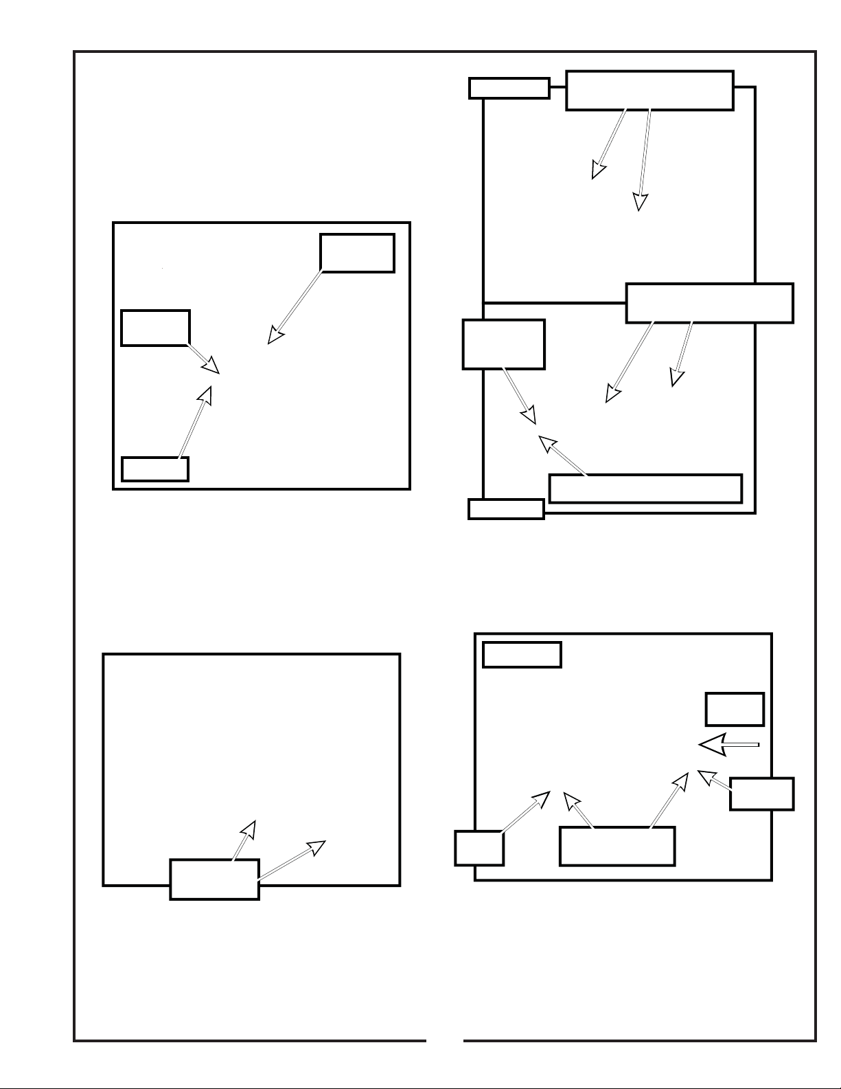
Refer to your Country Clipper owners manual for
instructions on how to properly remove the drive belt
from the engine pulley. After removing the drive belt from
the engine pulley, disconnect the wiring harness on the
clutch assembly. Remove the hardware that secures the
clutch assembly to the engine shaft. Remove the clutch
assembly from the engine shaft. Remove the bushing
from the underside of the clutch assembly, where the
pulley is located. Refer to Figure 2-1.
NOTE:
14-19.
NOTE:
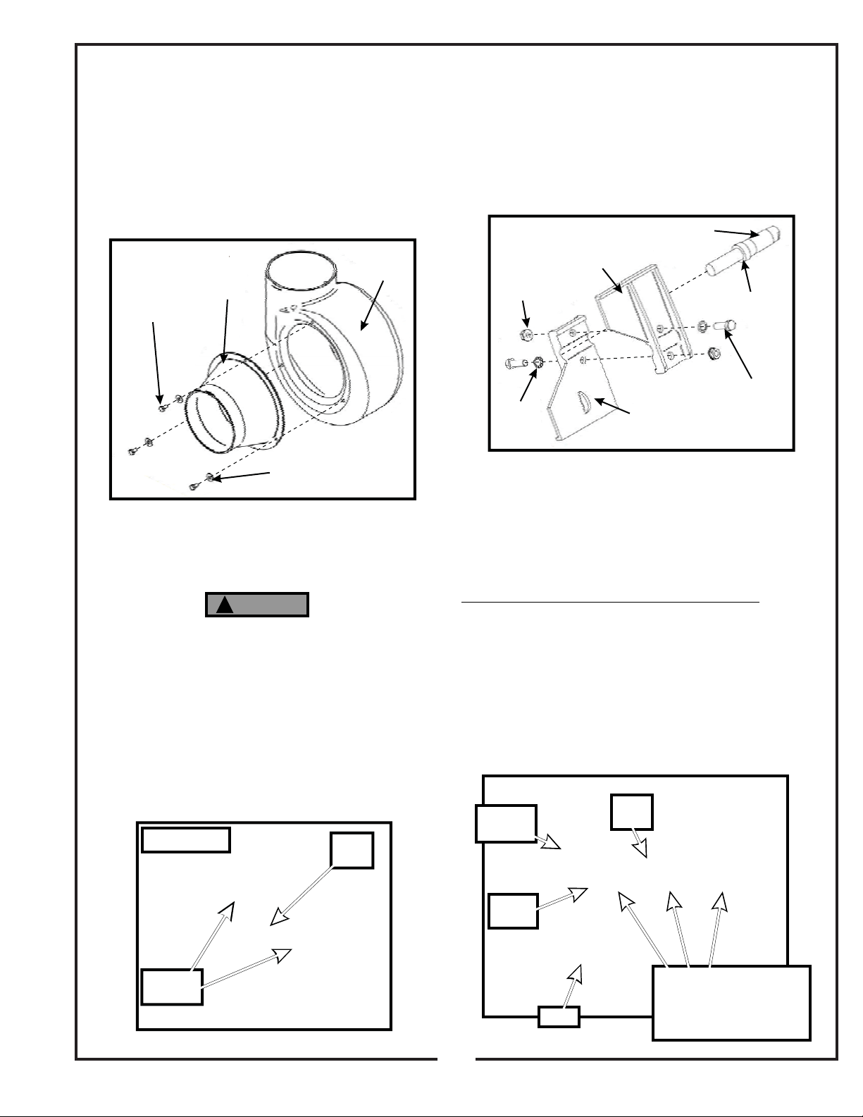
1-1/8” DIAMETER CRANKSHAFT
1” DIAMETER CRANKSHAFT
Make sure that the clutch stop is inline with the
pin upon re-installation of the clutch, and that the wiring
harness is re-connected.
Replace the bushing and hardware with engine
pulley assembly number 15 P#(A1038) and secure the
pulley assembly to the clutch using (1) 7/16”-20 x 3-3/4”
HHCS P#(K0350) and (1) 7/16” lock washer P#(K0140).
Replace the bushing and hardware with engine
pulley assembly number 12 P#(A0728) and secure the
pulley assembly to the clutch using (1) 7/16”-20 x 3-3/4”
HHCS P#(K0350) and (1) 7/16” lock washer P#(K0140).
The added pulley will power the collection system.
Reattach the drive belt to the
engine pulley.
For the 24HP & 27HP Kohler Engines, 22HP & 21HP
Kawasaki Engines and 23HP Briggs and Stratton
Engines:
For the 18.5HP, 22HP & 26 HP Briggs and Stratton
Engines and the 19HP Kawasaki Engine and 20HP
Kohler:
Torque the bolt to 55 ft./lbs.
Remove Drive Belt
From Engine Pulley
Disconnect
Wiring Harness
Remove
Hardware
Added
Engine Pulley
(1) 7/16” Lock Washer
(1) 7/16”-20 x 3-3/4” HHCS
Remove
Bushing
Clutch
Stop
Clutch
Pin
Electric Clutch
Assembly
Figure 2-1
Table of contents
Other Peco Lawn Mower Accessories manuals

Peco
Peco 39621223-28 User manual

Peco
Peco Pro 12 DFS 49621204 User manual

Peco
Peco 23651201 User manual

Peco
Peco Country Clipper XLT Series User manual

Peco
Peco Pro 12 DFS 37621231 User manual

Peco
Peco Pro 12 DFS 49651201 User manual

Peco
Peco Pro 12 DFS 49621203 User manual

Peco
Peco 50031303-54 User manual

Peco
Peco 21621209 User manual

Peco
Peco PRO2B+ 28120901 User manual

Peco
Peco 50721201 User manual

Peco
Peco 21621207-08 User manual

Peco
Peco 49120907 User manual

Peco
Peco Pro Series User manual

Peco
Peco 37641401 User manual

Peco
Peco Pro 2 BAGGER 23020907 User manual

Peco
Peco 22131501 User manual

Peco
Peco 37721231 User manual

Peco
Peco PRO2B+ 28120901 User manual

Peco
Peco 28621206 User manual