Pedibal E-CRUIZA User manual
User Manual
Important Recommendations:
• Packaging Retention: It's advised to keep the shipping carton. It will be beneficial for any potential servicing needs or product returns.
• Keys: Your e bike comes with two keys. We suggest keeping them in separate locations. Consider getting a third key made, as direct
replacements are not available.
• Battery Care: If you plan on not using your e bike for extended periods, ensure the battery remains charged. This practice aids in prolonging
its lifespan. Further details can be found in the instruction section.
• Instruction Manual: Dedicate some time to go through the manual thoroughly. It's packed with crucial information on usage and safety
measures. Your safety and understanding are paramount to us.
pedibal.com
@pedibal
@pedibal
@pedibalbikes

Table of Content
INTRODUCTION ---------------------------------------------------------------------- 1
IMPORTANT SAFET MAINTENANCE ----------------------------------------------- 2
PART DESCRIPTION ----------------------------------------------------------------- 3
ASSEMBL --------------------------------------------------------------------------- 4
CONTROL & DISPLA -------------------------------------------------------------- 18
BATTER & RANGE ---------------------------------------------------------------- 20
MAINTENANCE -------------------------------------------------------------------- 22
GENERAL --------------------------------------------------------------------------- 23
SAFET ----------------------------------------------------------------------------- 24
1
Introduction
Congratulations on your new Pedibal e bike purchase! We're thrilled you chose us. Our
commitment to excellence ensures a high quality product that we believe will bring you
countless memorable rides.
At Pedibal, we don't just pride ourselves on the quality and longevity of our bikes; we're also
staunch advocates for rider safety. Should you encounter any issues or have concerns, our
dedicated team is always here to assist.
This manual is your guide to understanding, operating, and maintaining your e bike safely. It's
essential to thoroughly read and familiarise yourself with the contents before your first ride.
Keep this manual handy for future reference.
Safety is paramount, and this guide contains several cautions and warnings to ensure you ride
with utmost care. If any aspect of the manual is unclear or raises questions, please don't hesitate
to reach out to Pedibal.
While we strive to cover various scenarios and precautions, it's impossible to predict every
situation one might encounter on the road. Riding any bicycle comes with inherent risks, and
ultimately, safety is the rider's responsibility.
We continuously update our documentation for accuracy and relevance. However, there might
be instances where updates or changes aren't immediately reflected. We appreciate your
understanding in this matter.
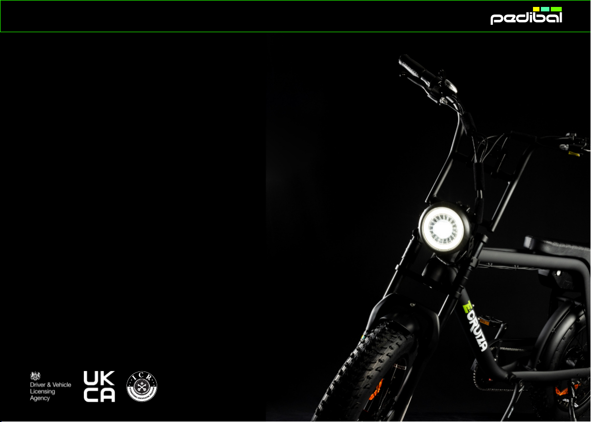
Lastly, it's worth noting that your e bike has been independently verified and meets the
requirements of the UKCA Certification Mark, pertaining to the standards outlined. Pedibal
proudly holds the responsibility for the certification and ensures that all necessary measures are
taken before the product hits the market. Furthermore, Pedibal tasked with maintaining an
effective internal production control to ascertain continued compliance with the Certification.
Thank you for trusting Pedibal, and here's to many enjoyable rides ahead!

2
Important Safety Maintenance
Congratulations on becoming a Pedibal Cruiza Owner. Now you have invested in the new E bike, we
just wanted to remind you of a few important points you should consider every time before you take
your new e bike out for a ride.
It has become apparent many of our customers are new to Electric Bicycles. Like any moving vehicle
with moving parts fixing points parts subject to moving/vibration. If it is not checked regularly, it can
become loose or detached. So we try to impress that it should become second nature to introduce
regular checks on a regular basis or prior to every use as a precautionary measure.
Check all fixing points are tight and secure and we
have highlighted those in the graphic on this page.
Pre Checks
Tighten All Screws Before Riding
• Always wear a helmet when riding
• Check brakes are secured and work sufficiently
• Check Tyres are inflated between 5 10PSI depndng on the ride intended
• Check pedals are tight
• Make sure light and reflectors are present/working
• Check handlebars and handlebar furniture are secure
To ensure the safety, make the following functional checks before riding:
Normal operation of the light, brake and power cut system.
Tire pressure (low pressure will effect range and speed).
Wheel axle tightness. Battery charging level.
Check Lights Front/Rear are working.
Braking system adjustment and free operation (wheel should spin freely, and brake levers should have minimal travel before engaging the brake).
3
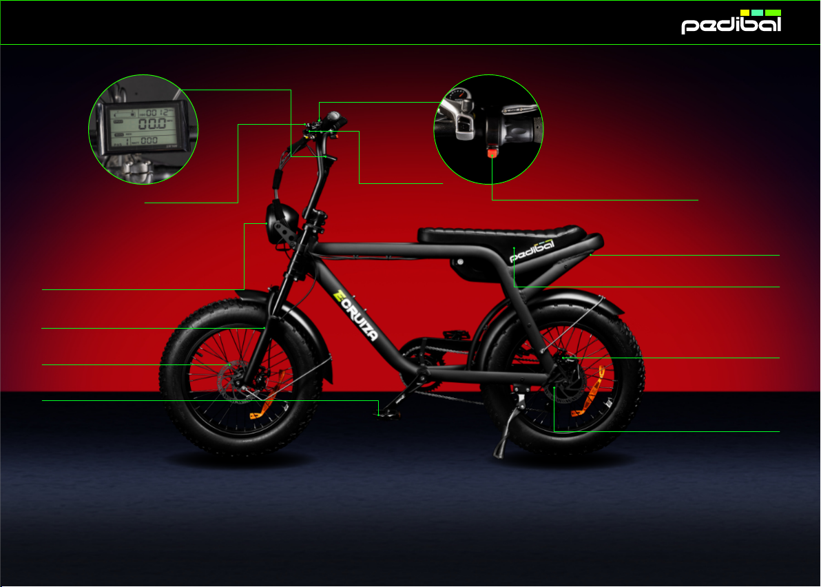
Rear Disc Brake Calliper
Daily Checks
Rear Wheel Hub Motor
Integrated LED Light Saddle
Independent Rear Light
LCD Control Centre
Rear Brake Lever
Front Brake Lever
Thumb shift gear selector
Twist & Go Power Cut Button
Front Disc Brake
Part Description
Front Fork Suspension
Pedal

Assembly
4
Before you continue to
complete the final assembly
please ensure you read the
instruction manual carefully.
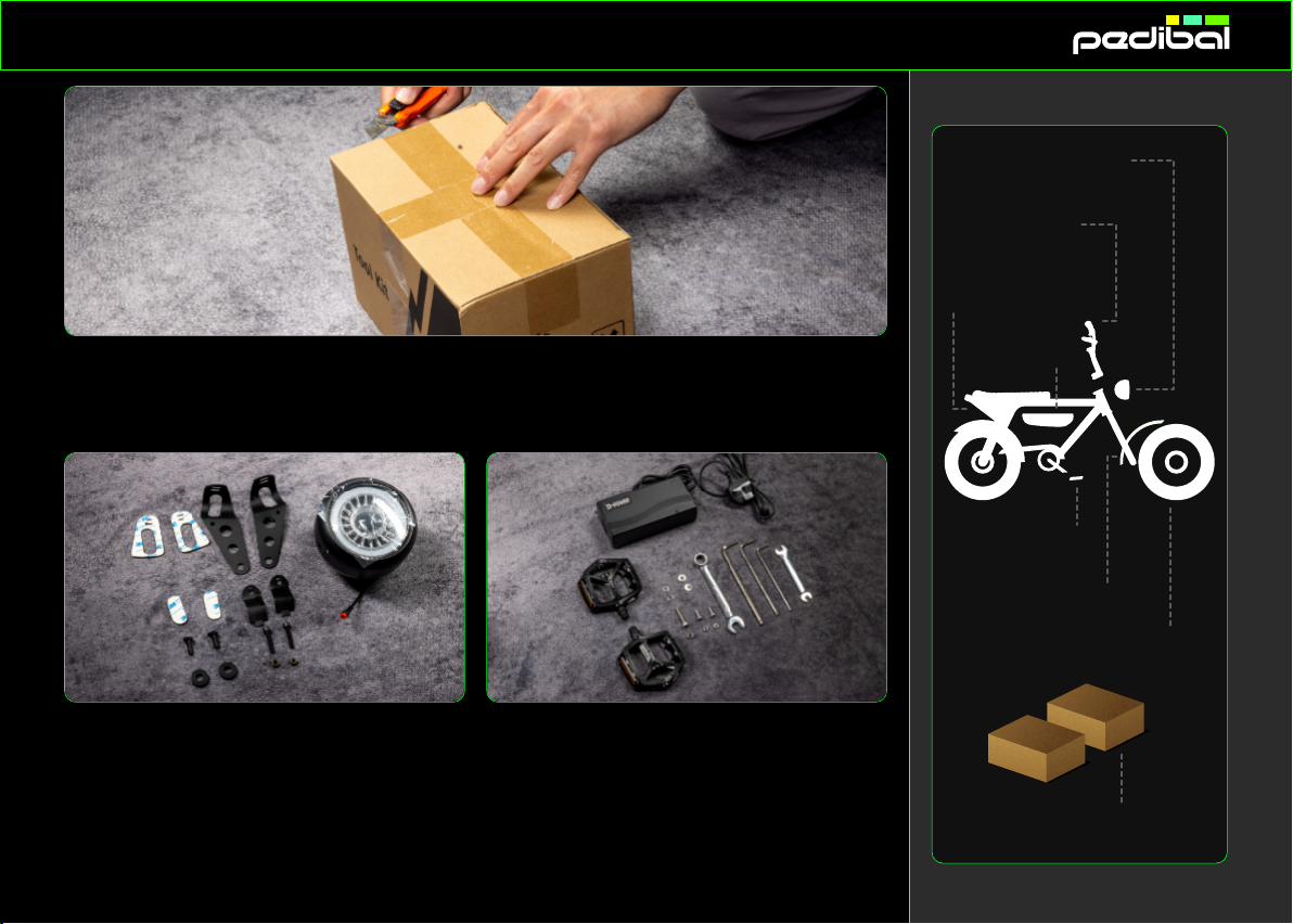
First step check for any
external damaged on the
shipping carton then
carefully cut the plastic
straps and open the top
flaps to reveal the bike.
Ideally allow sufficient
space to allow room to
manoeuvre to remove and
assemble to bike safely it
will take two people to lift
and hold the bike during
the final assembly, First
remove the two accessory
cartons then carefully lift
the bike away from the
carton.
1 Unbox In the Box
Main Frame
2 x Pedals
Front Wheel
2 x Boxes of Accessories
Front Mudguard
Handle Bar
& Stem
Head Lamp
Battery
Assembly
In the Box
Main Frame
2 x Pedals
Front Wheel
2 x Boxes of Accessories
Front Mudguard
Handle Bar
& Stem
Head Lamp
Battery
Remove the parts/tools located in the two accessory boxes and check parts receive match those identified
in the parts list section of the instruction manual.
Box 1:
1 x Lamp 2 x Long bracket
2 x short clamp 2 x bracket fixing bolt
2 x washers 2 x lamp fixing bolt
2 x washer 2 x large foam adhesive spacer
2 x small foam adhesive spacer
Box 2:
1 x 54v Charger & power cable
2 x Pedals (L&R) 1 x Mudguard fixing bolt
2 x washer 1 x locking nut
2 x M5 15MM mudguard bolts
2 x washers 1 x 15mm spanner
1 x 10mm spanner 3 x Allen keys
5
2 Organise

Assembly
In the Box
Main Frame
2 x Pedals
Front Wheel
2 x Boxes of Accessories
Front Mudguard
Handle Bar
& Stem
Head Lamp
Battery
Carefully remove main packaging to access the
components to be assembled please note a hobby
knife or cable cutter may be required to remove the
cable ties used to secure the bike during transit.
Leave packaging on the frame until other parts have
assembled and tested to help protect from damage
during assembly.
Carefully unclip the front wheel from the frame
ready for assemble only after Front mudguard has
been fitted.
Prepare all of the parts and fixing components for
easy access prior to assembly.
2 Organise
6

Assembly
Position
Parts & Tools
First assembly point is the
handlebar remove the 4 Allen
bolts from the headset then
remove the headset clamp.
With another person holding the
handlebar present the handlebar
to the headset and place the
clamp in position.
Using the 4mm Allen key tighten
the 4 x Allen bolts in a diamond
format to ensure even pressure is
applied across the clamp when
secure.
7
3 Handlebar
Assembly
Position
Parts & Tools
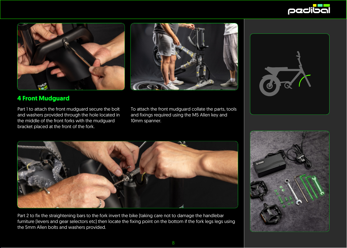
Part 1 to attach the front mudguard secure the bolt
and washers provided through the hole located in
the middle of the front forks with the mudguard
bracket placed at the front of the fork.
To attach the front mudguard collate the parts, tools
and fixings required using the M5 Allen key and
10mm spanner.
4 Front Mudguard
Part 2 to fix the straightening bars to the fork invert the bike (taking care not to damage the handlebar
furniture (levers and gear selectors etc) then locate the fixing point on the bottom if the fork legs legs using
the 5mm Allen bolts and washers provided.
8
Table of contents
Other Pedibal Bicycle manuals


