peerless-AV PeerAir Pro HDS300 User manual

ISSUED: 12-22-14 SHEET #: 180-9064-4 01-20-16
User Manual and Installation Guide
Models:
HDS300
HDS300-2
HDS300-3
HDS300-4
HDS300-5
HDS300-6 READY
®
Powered by
P
owere
d
b
y

ISSUED: 12-22-14 SHEET #: 180-9064-4 01-20-16
2
Safety Precautions .........................................................................................................................................................................3
Read Before Operating Equipment ........................................................................................................................................3
Unit Care Recommendations .................................................................................................................................................3
Introduction .....................................................................................................................................................................................4
Features .................................................................................................................................................................................4
Packaging Contents ..............................................................................................................................................................4
Product Specifications.....................................................................................................................................................................5
Video Format Supported............................................................................................................................................... 5
Audio Format Supported............................................................................................................................................... 5
Wireless Connection ..................................................................................................................................................... 5
Transmitter Front....................................................................................................................................................................6
Transmitter Back ....................................................................................................................................................................7
Receiver Front........................................................................................................................................................................8
Receiver Back ........................................................................................................................................................................9
Remote Control ....................................................................................................................................................................10
Remote Control Battery Installation And Replacement ........................................................................................................ 11
Installation And Operation .............................................................................................................................................................12
Connecting Source Components To The Transmitter ..........................................................................................................12
IR Flasher Installation (Setting Up IR Remote Control Capabilities for Source Devices) ....................................................13
IR Extender Installation ........................................................................................................................................................13
Connecting The Receiver To The Display Device ................................................................................................................14
Powering-Up The PeerAir™ Pro Wireless AV Multi-Display System ..................................................................................14
Input And Output Selection ..................................................................................................................................................15
Multicast Mode - Pairing Additional Receiver(s) With The Transmitter ...............................................................................16
Peer-To-Peer LAN (Wired) Mode Installation.......................................................................................................................16
Tips.......................................................................................................................................................................................17
Indicator Lights Decoded .....................................................................................................................................................17
Factory Reset.......................................................................................................................................................................17
How To Check The Firmware Version ..................................................................................................................................17
Supported Video Formats ....................................................................................................................................................18
Compliance Statements ................................................................................................................................................................18
FCC Compliance..................................................................................................................................................................18
CE Compliance ....................................................................................................................................................................18
Warranty ........................................................................................................................................................................................19
Contact Information .......................................................................................................................................................................19
CONTENTS

ISSUED: 12-22-14 SHEET #: 180-9064-4 01-20-16
3
SAFETY PRECAUTIONS
Read Before Operating Equipment
Thank you for purchasing our product. Before using it, please read this user manual carefully and follow the instructions
correctly for safe operation. Please keep this manual handy for future reference.
Unit Care Recommendations
• Unit can be placed vertically (preferred) or horizontally.
• To clean, use a soft, dry cloth only. Do not use water or other cleaning products as they may cause
electrical failure or damage the surface of the product.
Keep the product out of reach of
children.
Keep the product away from
external heat sources such as
heaters or stoves.
Do not insert foreign objects into
the unit.
Do not place the unit on an
unstable surface or in a poorly
ventilated area.
Make sure to plug the AC power
adaptors firmly into wall outlets.
Do not use the unit near any
flammable substances or
combustible sprays.
If any part of the AC power
adaptor looks damaged, do not
use the product and immediately
call Peerless-AV Customer Care at
1-800-865-2112.
Keep the product unplugged if
unused for an extended period
of time.
If there is any unusual sound,
smoke or odor coming from the
product, immediately unplug the
product and call
Peerless-AV Customer
Care at 1-800-865-2112.
Keep the battery of remote control
out of reach of children.
Do not attempt to open the
outer case of the Transmitter or
Receiver. Doing so will void the
product warranty.
Keep the remote control away
from humidity and/or liquids.

ISSUED: 12-22-14 SHEET #: 180-9064-4 01-20-16
4
PeerAir™ Pro Wireless AV Multi-Display System powered by HD Flow™3 provides Full HD 1080p signal transfer, including 3D
signal*, without the hassle of running cables. Create brilliant HD quality multimedia for signage, presentations, or entertainment
in any location, completely un-tethered to your source device!
By simply connecting the Transmitter to a multimedia device such as a computer, set-top box, or Blu-ray™ player and
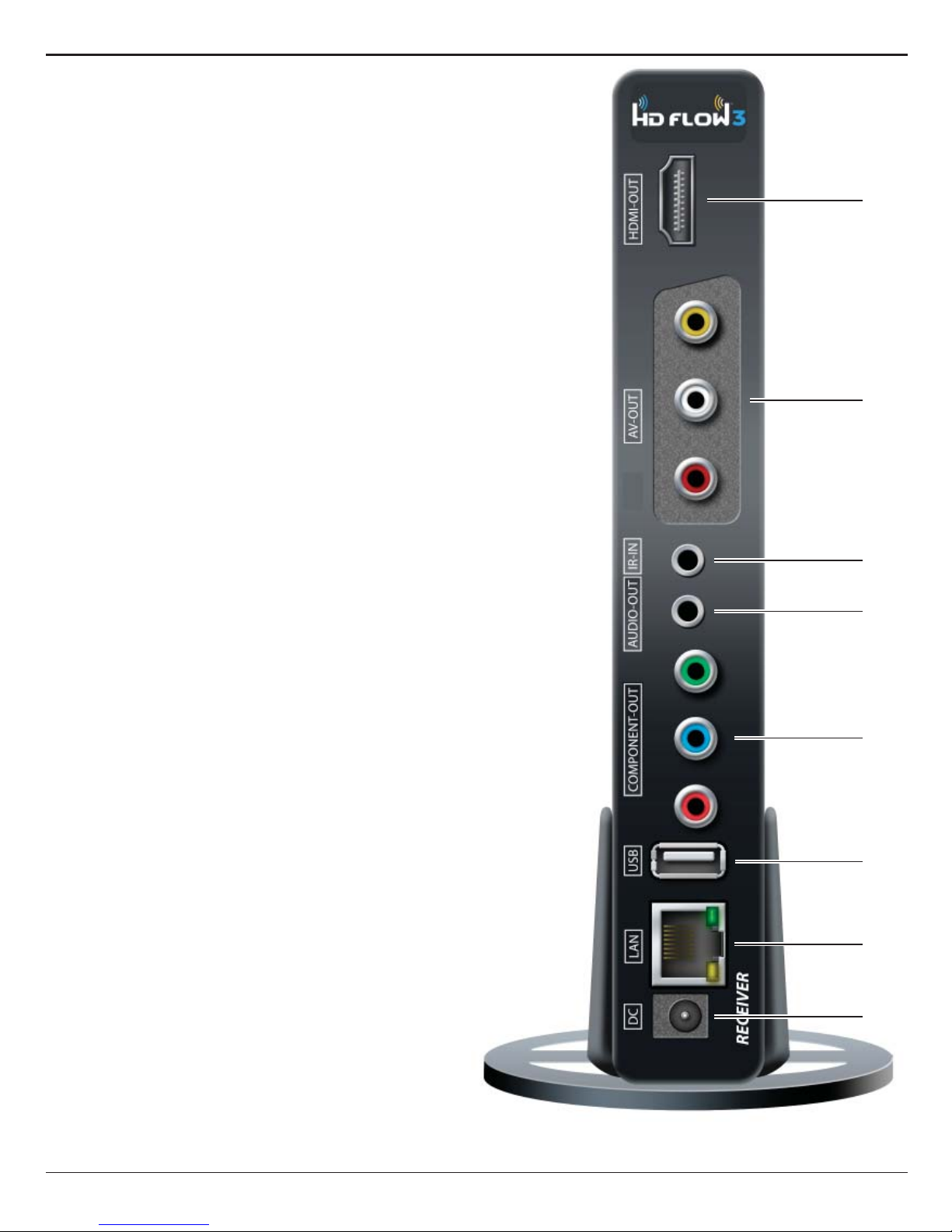
connecting the Receiver to a display device, instant high definition digital audio and video can be placed into in any commercial
or residential setting. PeerAir™ Pro Wireless AV Multi-Display System transmits through walls and floors to allow the
components to be neatly tucked away in an AV rack or media cabinet, and is the ideal solution for quick and easy installation
where running cable is cost prohibitive or simply not an option.
* Works with passive 3D signals
Features
• Low latency: ≤40ms.
• Supports both digital (HDMI) and analog (Component, Composite) video/audio.
• Supports Wireless or Wired connection - IEEE 802.11n 5 GHz WiFi, LAN connection.
• Two internal antennas (supporting MIMO).
• HDCP v1.3 compliant.
• Supports DTV and VESA standard resolutions (see "Supported Video Formats" section)
• Supports passive 3D content.
• Plug and play setup requires no software programming.
Package Contents for base HDS300 system
Ensure that the following items are present in the package. If any items are missing or damaged, please call Peerless-AV
Customer Care at 1-800-865-2112 (available 7:00am - 7:00pm CST Monday - Friday).
Transmitter Remote ControlReceiver
IR-Flasher
Component
Adaptor
Battery Manual
Stand (2)
Quick Start Guide
AC Adaptor (2)IR-Extender
(HDS300 only)
ISSUED:12-22-14 SHEET #: 180-9064-1
User Manual and Installation Guide
Models:
HDS300
HDS300-2
HDS300-3
HDS300-4
HDS300-5
HDS300-6 READY
®
Poweredby
P
owere
d
b
y
Step7 While turning on the display device the PeerAirTM Pro Wireless AV Multi-Display System will be going through the startup process. This
processmaytake up to 45 seconds to complete. The Power/Linkindicator lights on the Transmitter and the Receiver will be flashing at first.
Flashingindicatesthat the units are establishing a secure connection. Wait until the connection is successfully established, indicated by the
Power/Linkindicatorlight becoming solid.
1xTransmitter
1xReceiver
2xStand
1xRemote Control
1xIRFlasher
1xIR Extender
1xComponent Adaptor
2xPower Adaptor
1xQuick Start Guide
1xUsers Manual
Step2 Connect the provided IR Flasher to the IR-OUT port on the Transmitter.
Findthelocation of the IR window on your source device and adhere the
IRFlashereye directly over the IR window on your source device.
NOTE:OneIRFlasher eye is to b e used for one compone nt device.
Step4 Install the IR Extender by plugging in the provided IR Ex tenderin to
theIR-INport on the Receiver and adhering the other end of the IR Extender
toavertical surface near the output device. Ensure that the IR Extender is in
alineof sight to the remote control that controls your source devices.
NOTE:ForMulticastmodel s, receivers t wo through six do not come w ith an IR Extender. AdditionalIRExtenders(HDS-
IRE)canbepurchas ed separately; vis it peerless-av.com fo r more information .
Step6 Turn on your display device (TV, monitor, projector,etc.).
Step3 Connect the display device (TV, monitor, projector, etc.)
totheReceiver.
Step5 Power-up the PeerAirTMPro Devices.
1.Plugin the power adaptor for the Transmitter and the Receiver to nearby
availablepoweroutlets.
2.Plugin the power adaptor end to the Transmitter and then to the Receiver.
3.Theunits will automatically turn-on. The average power-on/sync time
isapproximately45seconds.
What’sin the Box
Installationand Setup
TroubleshootingTips
TipTheIRwindow
maybeeasierto
locatewithadire ct
lightshiningon
sectionsofthe
frontpanelofthe
componentdevice.
Asmallflashlight
workswell.
Power/Source
SelectionButton
Step1 Connect the Transmitter to the source devices
(Blu-ray™Discplayer,set top box, gaming console, etc.).
Step9 Turn on the desired source device that is connected to
theTransmitter.
Step11 Play the source device content and enjoy up to Full HD 1080p
wirelessentertainmentexperience.
• Checkthemedia source resolution. The display device must be able
tosupportthe resolution of the media source that is being streamed.
UtilizingtheINFO button will allow you to see the resolution data that
thedisplaydevice supports. If the display device support s the highest
resolutionof720p but the source device is outputting 1080p content,
thecontentneeds to be down-scaled to the maximum resolution of the
displaydevice,in this case 720p.
ReceiverOutputIndicator Light Blinks:
• Makesurethat yourdisplay dev ice,s ourcedevice and the
PeerAirTMPro
units
areallturned ON and the Receiver is properly connected to the output device.
• Verifythatthe Receiver is set to the appropriate output port.
• Checktheresolution setting of your source device. This may need to be
changedtoa resolution supported by the
PeerAirTMPro
unit.Reference
theResolutionChart in the
PeerAirTMPro
Manualfor compatibility.
Referenceyoursource devices’ manual for instruction on changing
theoutputresolution.
Iftheabove troubleshooting tipsdo not re solvethe issues for a unicast setup,
pleasereferencethe Factory Reset Section of the PeerAirTM Pro Manual.For a
multicastsystemconfiguration, please contact Peerless-AV Customer Care at
800-865-2112forfurther instruction.
Step8 Select the output that connects the Receiver to the display using
thePower/SourceSelection Button or the provided remote control.
Theoutputindicator light will become solid and the HD Flow logo will
appearonthe display device.
Step10 Select the desired source or device input on the Transmitter
usingthePower/SourceSelection But tonor the remote control.
Transmitterand/orReceiverIndicator Lights are all Blinking:
• ThePeerAirTMPro units are establishing a connection. It can take
upto45 seconds for the PeerAirTMPro unit s toe stablish a complete
connection.Iftwo minutes have passed and the units have not
establishedaconnection, unplug the power cable, wait 30 seconds
andreconnectthe power supply to the units.
TransmitterorReceiverPower Indicator Light is OFF:
• Checkandverify the power supply connection.
TransmitterInputIndicatorLight Blinks:
• Makesurethat yours ourcedevice is turn ed ON and the cable
isproperlyconnected.
• Verifythatthe Transmitter is set to the appropriate input port.
• Checktheresolution from your source device. This may need to be
changedtoa resolution supported by the PeerAirTM Pro Wireless
AVMulti-DisplaySystem. Reference the Resolution Chart in the
PeerAirTMProManualfor compatibilit y.Reference your source
devices’manualfor instruction on changing the output resolution.
ReceiverPowerIndicatorLig ht Blinks:
• Verifythatthe
PeerAirTMPro
Transmitterand Receiver are within
therecommendedrange of 210 feet. Physical obstructions such as
walls,floorsand ceilings between the Transmitter and Receiver may
decreasethestrength of the connection signal and reduce the overall
transmissionrange.
Ifaconnection has been established and the HD Flowlogo can be seen
onthedisplay device, but contentis not playing:
• Makesurethat the input/outputcables are properly connected.
• Verifythatthe Transmitter is set to the appropriate input port.
WarningDo not place the
PeerAirTM
Prounitsnear other devices that
emitexcessiveamounts of heat.
Increasedtemperaturesmay
causethePeerAirTMPro Transmitter
orReceiverunit to malfunction
orstopworking.
QuickStartGuidef or PeerAirTM Pro Wirel ess AV Multi-Disp lay System -LIT-0906
Power/Source
SelectionButton
©2015PeerlessIndust ries, Inc. P eerless-AV ™ is a trademark of P eerless Indu stries, Inc . All rights r eserved.
HDFlow™isa trademark of I Do I t, LTD. Other par ties’ marks ar e the propert y of their respe ctive owner s. www.peerless-av.com
Quick StartGuide
ModelNo.HDS300 (-2,-3, -4, - 5, -6)
POWER POWER
RECEIVERTRANSMITTER
ON OFF
MENU SCAN
/BACK
INFO
/OK
HDMI HDMI1
COMPONENTPC HDMI2
AV AV HDMI3
RECEIVER
HDMI
COMPONENT
AV
PoweredbyPoweredb
y
TipRepeatSteps
3-11toconnectmore
thanoneReceiverunit
(HDS300-2,HDS300-3,
HDS300-4,HDS300-5,
HDS300-6)
POWER POWER
RECEIVERTRANSMITTER
ON OFF
MENU SCAN
/BACK
INFO
/OK
HDMI HDMI1
COMPONENTPC HDMI2
AV AV HDMI3
TRANSMITTER
HDMI1
PC HDMI2
AV HDMI3
INTRODUCTION

ISSUED: 12-22-14 SHEET #: 180-9064-4 01-20-16
5
HDS300
Video Input
(Transmitter)
3x HDMI up to 1080p60
1x HDMI pass-thru output (pass-thru port mirrors HDMI 1)
1x PC Video
1x Component & composite (via included dongle)
Video Output
(Receiver)
1x HDMI up to 1080p60
1x Component
1x Composite
Encoding H.264 Baseline Profile
Decoding H.264 Baseline, Main, High Profile
Wireless Connection IEEE 802.11n
Wire Connection RJ45 LAN port, 10/100/1000 Base
USB Type "A" both Transmitter and Receiver for firmware updates only
Audio 2 CH PCM, 48kHz, 16 Bit
Audio Input 3.5mm Stereo Mini Jack (Transmitter)
Audio Output 3.5mm Stereo Mini Jack and RCA Stereo Jack (Receiver)
Video Resolution 480i/p, 720p, 1080i/p (24/30 fps)
Video Latency 40ms
Frequency 5.18-5.24 & 5.75 - 5.81GHz
Range 210 ft (64M)
Multicast Up to 6 receivers (Requires additional receiver units)
Security WPA2 Personal and AES
HDCP Version 1.3
Antenna Type MIMO, 2x Internal
IR Emitter 3 IR Emitters on a single wire
IR Extender 1 included
Remote Control 17 button IR remote
Power 12 VDC at 2 Amps (both transmitter and receiver)
1. Video Format Supported
• Digital Video
HDMI - Up to 1080p
• Analog Video
Composite – 480i
Component – 1080i
VGA – Up to 1920x1080
2. Audio Format Supported
• Analog
• Digital
• Receiver outputs stereo audio
3. Wireless Connection
• Unicast (Peer-to-Peer) Wireless Mode
• Multicast Wireless Mode
4. WiFi Channel Frequencies
• 5.18-5.24 & 5.75 - 5.81GHz
PRODUCT SPECIFICATIONS

ISSUED: 12-22-14 SHEET #: 180-9064-4 01-20-16
6
4
5
6
7
8
Transmitter Front
1. Power/Link Indicator Light
• Blinking indicator light - Establishing link between the
Transmitter and the Receiver.
• Solid indicator light - Link between the Transmitter
and Receiver has been established and is ready for
signal transmission.
2. HDMI 1
• The HDMI 1 indicator light will be illuminated when
the HDMI 1 port is selected for video input.
• If there is no signal, and/or the cable is not
connected, the indicator light will blink.
3. HDMI 2
• The HDMI 2 indicator light will be illuminated when
the HDMI 2 port is selected for video input.
• If there is no signal, and/or the cable is not
connected, the indicator light will blink.
4. HDMI 3
• The HDMI 3 indicator light will be illuminated when
the HDMI 3 port is selected for video input.
• If there is no signal, and/or the cable is not
connected, the indicator light will blink.
5. PC
• The PC indicator light will be illuminated when the PC
In port is selected for video input.
• If there is no signal, and/or the cable is not
connected, the indicator light will blink.
6. AV
• The AV indicator light will be illuminated when the AV
In port (Composite) is selected for the video input.
• If there is no signal, and/or the cable is not
connected, the indicator light will blink.
7. IR Window
• IR receiving window enables remote control of the
transmitter and the receivers.
8. Link/Source Selection Button
• When powered on: Press for one second to select
the video input source. Each press of the button
will cycle through the available video input "HDMI1→
HDMI2→HDMI3→PC→AV →HDMI1" in sequence.
• Press and hold for 8 seconds until all indicator lights
blink synchronously, you are now in Scan/Pairing
Mode.
3
2
1

ISSUED: 12-22-14 SHEET #: 180-9064-4 01-20-16
7
4 3
6
7
8
9
10
2 1
5
Transmitter Back
1. HDMI 1 IN
• HDMI1 input port.
2. HDMI OUT
• Pass-Thru for a local display from HDMI 1 input.
3. HDMI 2 IN
• HDMI2 input port.
4. HDMI 3 IN
• HDMI3 input port.
5. USB
• USB port is used for service only.
6. IR-OUT
• Connects IR Flasher to the Transmitter for remote
control of external devices which are connected to
the Transmitter (i.e. Blu-Ray player, DVD, STB, etc).
7. PC AUDIO-IN *
• Stereo audio input port for PC, component, or
composite source.
8. PC-IN (VGA)**
• Supports component and composite input with
included Component/Composite Adaptor.
9. LAN
• LAN port used for wired connection alternative.
10. DC
• 12V DC power input.
*For the audio part of a component media source, use the PC
Audio input port with a 3.5mm to RCA cable (not included).
** If using the PC Video input port for component (YPbPr) or
composite media source, use the included
Component/Composite to VGA adaptor. For composite, use
the green jack on the adaptor for the yellow video plug.

ISSUED: 12-22-14 SHEET #: 180-9064-4 01-20-16
8
Receiver Front
1. Power/Link Indicator Light
• Blinking indicator light - Establishing link between the
Transmitter and the Receiver.
• Solid indicator light - Link between the Transmitter
and Receiver has been established and is ready for
signal transmission.
2. HDMI
• The HDMI indicator light will be illuminated when the
HDMI port is selected for video output.
• If there is no signal, and/or the cable is not
connected, the indicator light will blink.
3. COMPO
• The COMPO (component) indicator light will be
illuminated when component output is selected for
video output.
• If there is no signal, and/or the cable is not
connected, the indicator light will blink.
4. AV
• The AV indicator light will be illuminated when the AV
port (composite) is selected for the video output.
• If there is no signal, and/or the cable is not
connected, the indicator light will blink.
5. IR Window
• IR receiving window enables remote control of the
transmitter and/or source components.
6. Link/Output Selection Button
• When powered on: Press for 1 second to select the
video output source. Each press of the button
will cycle through the available video outputs
"HDMI→COMPO→AV →HDMI" in sequence.
• Press and hold for 8 seconds until all indicator lights
blink synchronously, you are now in Scan/Pairing
Mode.
1
2
3
4
5
6

ISSUED: 12-22-14 SHEET #: 180-9064-4 01-20-16
9
1
2
3
4
5
6
7
8
Receiver Back
1. HDMI-OUT
• HDMI output port
2. AV-OUT
• Composite video output port
3. IR-IN
• Connects IR Extender in order to
extend IR reception range.
4. AUDIO-OUT*
• 3.5mm stereo audio output
port for component output.
5. COMPONENT-OUT*
• Component Video
output port
6. USB
• USB port used for service
7. LAN
• LAN port used for wired connection
alternative
8. DC
• 12V DC Power Input
* For the audio part of a component media source, use the PC
Audio Output port with a 3.5mm-to-RCA cable (not included).

ISSUED: 12-22-14 SHEET #: 180-9064-4 01-20-16
10
POWER POWER
RECEIVER TRANSMITTER
ON OFF
MENU SCAN
/ BACK
INFO
/ OK
HDMI HDMI1
COMPONENT PC HDMI2
AV AV HDMI3
1
7
4
2
6
5
3
8
Remote Control
1. POWER ON Button
• Turns the Transmitter and Receiver power ON
2. POWER OFF Button
• Turns the Transmitter and Receiver power OFF
3. INFO/OK*
• Displays the following information on the screen:
Transmitter - WiFi IP, LAN IP, frequency, Single/
Bonded Channel, Source Resolution, and software
version.
Note: The Transmitter unit’s information will
only be displayed if the connection between the
Transmitter unit and Receiver has been
established.
Receiver - WiFi IP, LAN IP, MAC Address, WiFi
Quality, SSID, Display Resolution, and Software
Version.
Monitor - Model number and EDID information of
connected display.
IR - IR Frequency
*Displayed information will disappear automatically after
30 seconds.
4. VIDEO OUT (Receiver)
• Selects the Audio/Video output port of the Receiver.
HDMI - Selects HDMI as the Audio/Video output.
Component - Selects Component as the
Audio/Video output.
AV - Selects AV as the Audio/Video output.
Note: Remote must be pointing directly at the Receiver to control its output settings. This may also be accomplished
without the use of the remote control by toggling between outputs via the Link/Output Selection Button on the Receiver.
5. VIDEO IN (Transmitter) - Selects the Video input port of the Transmitter.
• HDMI1 - Selects HDMI1 as the Audio/Video input.
• HDMI2 - Selects HDMI2 as the Audio/Video input.
• HDMI3 - Selects HDMI3 as the Audio/Video input.
• PC - Selects VGA/Component as the Audio/Video input.
• AV - Selects Composite as the Audio/Video input (requires included
Component/Composite adaptor).
6. Scan
• Selects Scan/Pairing mode. System will re-scan among 8 possible WiFi frequencies and select the best available
channel. The channel selected will be displayed when “Info” is pressed.
7. MENU and DOWN Buttons
• Disabled - for future use.
8. UP Button
• This will scroll through the possible IR frequencies. This device accommodates most IR protocols in use today. To do
so it will require selecting the one of four possible carrier frequencies available for IR control. Press the UP arrow to
scroll between 31 KHz, 38 KHz, 47 KHz and 57 KHz frequencies.
• Select a frequency and try your source remote. If the control responds, then you have selected the correct one. If the
device does not respond, try another frequency. If no frequencies seem to work, ensure the IR emitter is located in the
correct location on the source component.

ISSUED: 12-22-14 SHEET #: 180-9064-4 01-20-16
11
Remote Control Battery Installation And Replacement
The battery clip is located on the bottom of the remote control.
2. Place the battery into
the clip, positive (+) end
facing up as shown.
3. Place the clip back into
the remote to complete
the installation.
1. Push the tab, located
on the left of the battery
clip, to the right and pull
out the clip.
Battery ClipTab

ISSUED: 12-22-14 SHEET #: 180-9064-4 01-20-16
12
2. VGA Media Source
• Video - Connect the VGA cable from the media
source’s VGA output to the Transmitter’s VGA input.
• Audio - A 3.5mm stereo audio cable is required (not
included) to transmit audio when using this input.
Connect the 3.5mm stereo audio cable from the VGA
source component’s audio output to the Transmitter's
PC AUDIO-IN port.
3. Component Media Source
• Video – Connect the Component Video
output (YPbPr) from the source, into the
Component/Composite Adaptor (included). Connect
the Component/Composite Adaptor
to the PC-IN port on the Transmitter.
• Audio - A 3.5mm stereo audio cable is required (not
included) to transmit audio when using this input.
Connect the 3.5mm stereo audio cable from the VGA
source component’s audio output to the Transmitter's
PC AUDIO-IN port.
• Connect HDMI cable from the Transmitter’s pass-
thru output port to the input of the display device
to enjoy the video coming through HDMI1 only.
Before starting the installation, please ensure that all source components (Blu-ray player, cable box, etc.) and the display
equipment (TV, display, projector, etc.) are turned off.
For initial setup of your PeerAir™ Pro system complete steps A, B, C, D, E and F in order.
A) Connecting Source Components To The Transmitter
1. HDMI Media Source
• Note: It is recommended that the HDMI1 input port be used if only one HDMI source component is present.
INSTALLATION AND OPERATION
• Connect HDMI cable from the source components
output to the Transmitter's HDMI1 or HDMI2 or
HDMI3 input port.

ISSUED: 12-22-14 SHEET #: 180-9064-4 01-20-16
13
B) IR Flasher Installation (Setting Up IR Remote Control Capabilities for Source Devices)
IR Flashers are provided to allow for control of up to three source devices using the device’s original remote control at the
Receiver location.
1. Connect the provided IR Flasher to the IR-OUT port of the Transmitter.
2. Find the location of the IR window on your component and adhere the IR Flasher Eye directly over the IR window of your
component.
• Note: One IR Flasher Eye is to be used for one component device.
• Tips: Most often the IR window on the source device is easier to locate with direct light shining on sections of the
front panel of the device (a small flashlight or a camera phone flashlight works well).
IR-OUT Port
IR Flasher Eye
4. Composite Media Source
• Video – Connect “yellow” composite video RCA to
green port on Component/Composite Adaptor.
• Audio – A 3.5mm stereo audio cable is required (not
included) to transmit audio when using this input.
Connect the 3.5mm stereo audio cable from the VGA
source component’s audio output to the Transmitter's
PC AUDIO-IN port.
C) IR Extender Installation(Optional)
Install the IR Extender by plugging in the provided IR Extender into the IR-IN port on the Receiver. (IR Extender use is optional.
Use the IR Extender when the Receiver is out of sight or to extend the range of the Receiver's IR reception range.)

ISSUED: 12-22-14 SHEET #: 180-9064-4 01-20-16
14
D) Connecting The Receiver To The Display Device
Note: Connect the Receiver to the display device using
the port with the highest capable resolution; HDMI port
is preferred. The PeerAirTM Pro is a video switch, and as
such will upconvert all inputs with resolutions of 480p,
720p, and 1080i/p through the HDMI Output.
1. HDMI Output to Display
• Connect the HDMI cable from the Receiver's
HDMI output to the display device's HDMI input.
2. Composite Output to Display
• Connect the composite RCA cable from
the Receiver's AV output to the display device's
composite input.
3. Component Output to Display
• Video - Connect the component video (YPbPr)
cable from the Receiver's COMPONENT-OUT to
the display device's component input.
• Audio - A 3.5mm-to-RCA stereo audio cable is
required (not included) to transmit audio when
using this input. Connect the 3.5mm end of the cable to the Receiver's AUDIO-OUT port, then connect the RCA side
of the cable to the RCA ports on the display device.
E) Powering-up The PeerAir™ Pro Wireless AV Multi-Display System
1. Plug in the power adaptors for the Transmitter and the Receiver to available power outlets.
2. Plug in the other end of the power cables to the Transmitter and then to the Receiver. The
units will automatically turn on.
3. Turn on your display device (TV, monitor, projector, etc.).
4. While turning on the display device, the PeerAir™ Pro System will be going through the
start up process. The process takes approximately 45 seconds to complete. The
Power/Link Indicator Light on the Transmitter and Receiver should be flashing at first.
Flashing indicates that the units are establishing a secure connection. Wait until the
connection is successfully established, indicated by a solid Power/Link light on the
Receiver.
NOTE!! The first time the system is connected it is best practice to do a Scan Pairing. This
will ensure that the system chooses the best available channel and also pairs itself under a
unique SSID (network name).
5. To Scan Pair the units wait for the units to establish a secure connection, indicated by a solid Power/Link light on the
Receiver. Then aim the remote at the receiver and press the Scan/Back button. You should see the lights on the Receiver
and Transmitter blink sequentially from top to bottom; then in various patterns. After about 30 seconds the Receiver will
successfully link with the Transmitter and then shut off and reboot itself. The entire process will take under 1 ½ minutes and
video will not appear on the display until the process is complete.
1
2
3

ISSUED: 12-22-14 SHEET #: 180-9064-4 01-20-16
15
F) Input and Output Selection
1. Select the output used to connect the Receiver to the display. There are two ways to choose output sources on the
PeerAir™ Pro Receiver:
a. Using the provided remote - Press the desired output while pointing the remote at the Receiver.
b. Using the Link/Output Selection Button on the Receiver - To toggle between outputs press the Link/Output Selection
Button for one second on the unit and release.
At this time the Output Indicator Light will become solid and the HD Flow™3 logo will appear on the display device if there
is no source providing content. The HD Flow™3 logo is only displayed when the receiver is working with the display, but no
content is coming from the transmitter.
2. Turn on the desired media source device that is connected to the Transmitter.
3. Select the desired media source input on the Transmitter. There are two ways to select the source input on the PeerAir™
Pro Transmitter:
a. Using the provided remote - Press the desired input while pointing the remote at the Transmitter.
b. Using the Link/Source Selection Button on the Transmitter - To toggle between Inputs press the Link/Source
Selection Button for one second on the unit and release.
4. Play the source device media content and enjoy up to a Full HD 1080p wireless entertainment experience.
Notes:
1. Audio and video sources will switch simultaneously whether using the remote or Link/Source Selection Button.
2. Inputs on the Transmitter and Receiver can be switched by pointing the remote at the Transmitter or Receiver ONLY if
the connection between Transmitter and Receiver has been established, indicated by a solid link light. If the connection
between Transmitter and Receiver has not been established, the inputs need to be selected at the location of each unit
using either of the above input and output selection methods.

ISSUED: 12-22-14 SHEET #: 180-9064-4 01-20-16
16
Multicast Mode - Pairing Additional Receiver(s) With The Transmitter (Optional)
Multicast Wireless Mode enables the Transmitter to stream AV media from one Transmitter to up to six Receivers.
Use the following instructions to pair the Receiver(s) to the current system, or follow the steps in the HDS300-R manual. The
system can have receivers added at any time.
Each Receiver will have to be paired with the Transmitter one at a time. Do not begin pairing another Receiver until the
previous Receiver has rebooted after pairing as described in the steps below. A maximum of 6 Receivers may be paired to one
Transmitter.
1. Press and hold the “Link/Source” button on the transmitter for 8 seconds. The lights will blink sequentially from top to
bottom. The transmitter will remain in pairing mode for 2 minutes or until it senses a Receiver trying to link.
2. Press and hold the “Link/Output” button on the desired Receiver for 8 seconds. The lights will first blink sequentially from
top to bottom; then in various patterns. After about 30 seconds the Receiver will successfully link with the Transmitter and
then shut off and reboot itself. The entire process will take under 1 ½ minutes and video will not appear on the display until
the process is complete. Video on the additional paired Receivers will be lost during this process.
3. Repeat steps 1 and 2 for each additional Receiver, if any.
Note: For 3 or more Receivers the system will change its mode from single channel to bonded channel. If Receivers are
removed from the system making it 2 or fewer Receivers total, the system should be factory reset to put it back into single
channel mode. Factory reset instructions can be found on page 16.
Peer-To-Peer LAN (Wired) Mode Installation
1. Connect the LAN cable between the LAN ports on the Transmitter and Receiver.
2. Plug both the Transmitter and Receiver into power.
3. When the PeerAir™ Pro system powers up it will detect the wired connection upon power up and not enter wireless mode.
The boot process should be complete in about 45 seconds. The WiFi indicator lights on the front of both the Transmitter
and the Receiver will be solid.
Available Multicast Models
Model Capability Mode
HDS300-2 streams to two display devices Multicast Wireless
HDS300-3 streams to three display devices Multicast Wireless
HDS300-4 streams to four display devices Multicast Wireless
HDS300-5 streams to five display devices Multicast Wireless
HDS300-6 streams to six display devices Multicast Wireless
Note:
To return the units back to WiFi mode, unplug power on both
Transmitter and Receiver, then unplug the LAN cable, and re-
power the Transmitter and Receiver. The video and audio will
be lost during this process.

ISSUED: 12-22-14 SHEET #: 180-9064-4 01-20-16
17
Tips
If the Transmitter and Receiver are not establishing a connection:
1. It is recommended to unplug the power to both units for 30 seconds and then plug them back in.
2. If the above tip does not assist, please reference the Factory Reset section of this manual.
If the connection has been established and the HD Flow™3 logo can be seen on the display device, but content is not playing
when initiated:
1. Ensure that source cables are properly connected.
2. Ensure the Transmitter is set to the proper input port and that the Receiver is set to the proper output port.
3. Ensure the source is operating.
4. The display device needs to be able to support the resolution of the media source that is being streamed. Utilizing the INFO
button, while connected via HDMI, will allow you to see the EDID resolution data that the display device accepts.
(Example - If the display device supports the highest resolution of 720p but the source device is outputting 1080p content,
the content needs to be downscaled to the maximum resolution of the display device, in this case 720p).
If pixelation is occuring on the screen aim the remote at the receiver and hit the Scan/Back button. The system will reboot and
scan for the best available channel.
If the HD Flow™3 logo nor the video content are being displayed, verify that the output selection on the Receiver and input
selection of the display are correct. Also, make sure cables are completely pressed into place and secure, and that the selected
source content is playing.
Indicator Lights Decoded
1. Transmitter/Receiver
• Power/Link Indicator Light:
Solid - Link between the Transmitter and Receiver(s) has been established and is ready for signal transmission.
• All Indicator Lights:
Flashing - Units are booting or resetting and establishing a secure connection for AV transfer.
Lights blinking sequentially from top to bottom - Unit is in Scan Pairing Mode searching for other PeerAir™ Pro
devices.
2. Transmitter:
• HDMI1, HDMI2, HDMI3, PC, AV - The indicator light will be lit to indicate the input that is currently selected. If the
selected input does not have a connection or the signal from the media source is not present, the selected input
indicator light will be flashing.
3. Receiver:
• HDMI, COMPO, AV - The indicator light will be lit to indicate the output that is currently selected. If no output device
is connected to the selected output port the indicator light will be flashing.
Factory Reset
CAUTION: Factory reset will revert all settings to factory defaults. It is not recommended to perform a factory reset
on multicast systems (systems with two or more receivers) as the pairing will be forgot. One will have to re-pair the
additional receivers if a factory reset is completed.
To complete a factory reset, complete each of the steps below for both the transmitter and receiver. These do not need to be
done at the same time.
1. Unplug the device from its power source.
2. Press and hold the Link/Source or Link/Output Selection button on the front panel. Plug the DC power back into the unit
being reset.
3. Continue holding the Link/Source or Link/Output Select button until the lights on the front of the unit blink at least 6 times.
4. Allow the system to re-start and show content.
How To Check S/W Version
1. Make sure the PeerAir™ Pro System is up and running.
2. Using the PeerAir™ Pro remote supplied, point it at the Receiver IR window. Press the Info/OK button. In the list of
information there will be stated “S/W Version:”

ISSUED: 12-22-14 SHEET #: 180-9064-4 01-20-16
18
O - Compatible X - Not Compatible ^ - Compatibility varies based on output device settings
Supported Video Formats
Notes:
1. 1600 x 1200p60 is a reduced
format.
2. PeerAir™ Pro simply relays the
input format of the video from
the Transmitter to the Receiver.
PeerAir™ Pro does not change
the video format. If you want to
change the output resolution,
you should change the format
on the external device which is
connected to the Transmitter.
3. When transmitting NTSC:480i or
PAL:576i from the Transmitter,
COMPONENT-OUT MUST be
used at the Receiver.
4. Only HDMI 480i resolution input
will provide composite AV-OUT
signal at the Receiver. For all
other resolutions, use
HDMI-OUT or
COMPONENT-OUT at the
Receiver.
5. PC-IN fully supports resolutions
noted above ONLY when
HDMI-OUT is used at the
Receiver.
Video
Standard Resolution HD Flow Transmitter HD Flow Receiver
HDMI D-Sub AV(CVBS) HDMI COMP AV(CVBS)
"VESA
Format
(PC standard)"
640 x 480p60 O O X O X X
640 x 480p70 O O X O X X
640 x 480p85 O O X O X X
800 x 600p60 O O X O X X
800 x 600p70 O O X O X X
800 x 600p85 O O X O X X
1024 x 768p60 O O X O ^ X
1024 x 768p70 O O X O X X
1024 x 768p85 O O X O X X
1152 x 864p60 O O X O ^ X
1152 x 864p70 O O X O X X
1152 x 864p85 O O X O X X
1280 x 800p60 O O X O X X
1280 x 960p60 O O X O ^ X
1280 x 960p70 O O X O X X
1280 x 960p85 O O X O X X
1280 x 1024p60 O O X O ^ X
1360 x 768p60 O O X O X X
1440 x 900p60 O X X O X X
1600 x 1200Rp601 O O X O ^ X
1600 x 900p60 O X X O X X
1680 x 1050p60 O O X O X X
"DTV
Format
(TV standard)"
720 x 480I60(NTSC) O O O X O O
720 x 576I50(PAL) O O O X O O
720 x 480p60 O O X O O X
720 x 576p50 O O X O O X
1280 x 720p50 O O X O O X
1280 x 720p60 O O X O O X
1920 x 1080i50 O O X O O X
1920 x 1080i60 O O X O O X
1920 x 1080p24 O O X O X X
1920 x 1080p25 O X X O X X
1920 x 1080p30 O X X O X X
1920 x 1080p50 O O X O X X
1920 x 1080p60 O O X O X X
FCC Compliance
This equipment has been tested and found to comply with the limits for a Class B digital device, pursuant to part 15 of the FCC
Rules. These limits are designed to provide reasonable protection against harmful interference in a residential installation.
This equipment generates, uses, and can radiate radio frequency energy and, if not installed and used in accordance with the
instruction manual, may cause harmful interference to radio communications. However there is no guarantee that interference
will not occur in a particular installation. If this equipment does cause harmful interference to radio or television reception, which
can be determined by turning the equipment off and on, the user is encouraged to try to:
1. Relocate the receiving antenna.
2. Increase the separation between equipment and Receiver.
3. Connect the equipment into an outlet on a circuit different from that to which the Receiver is connected.
4. Consult the dealer or an experienced radio/TV technician for help.
CE Compliance
This device has been tested and found to comply with the following European Union directives: Electromagnetic Capability
(89/336/EMC), Low Voltage (73/23/EEC) and R&TTED (1999/5/EC).
COMPLIANCE STATEMENTS

ISSUED: 12-22-14 SHEET #: 180-9064-4 01-20-16
19
1 YEAR LIMITED WARRANTY
The HDS300 is distributed by Peerless Industries, Inc. using the highest quality components and technology available. The
Product is warranted to be free from defects in material and workmanship, given normal use and care, for 1 Year from the
original purchase date with proof of purchase. Please retain a copy of your receipt as you will need this to obtain warranty work.
We will repair or replace the product which fails as a result of such a defect during the warranty period. The accessories are not
covered by this warranty.
This warranty is the customers’ exclusive remedy for product defect and does not apply to:
• Any modifications made to the product in any way by the customer
• Attachments to the product by the customer that causes product damage
• Any product which the seals/and or serial numbers and/or logos have been broken, removed, or tampered with, defaced, or
altered in any manner
• Damage caused by abuse, misuse, accident, water, or theft
• Physical damage
• Loss of the Accessories
Except as stated above, Peerless Industries, Inc. makes no express or implied warranties as to
any product, in Particular, makes no warranty of merchantability or fitness for any particular purpose. Peerless Industries, Inc.
shall not be liable for consequential or incidental damages arising from any product defect. Our liability is limited to replacement
of any defective product as stipulated under the warranty conditions. Peerless Industries, Inc. expressly disclaims all warranties
not satisfied in this limited warranty. Any implied warranties that may be imposed by law are limited to the terms of this limited
warranty.
WARRANTY
Customer Care
Need help with installation or set up? Call Peerless-AV Customer Care
1-800-865-2112 (available 7:00am- 7:00pm CST, Monday - Friday), or email us at info@peerless-av.com.
Peerless -AV
2300 White Oak Circle
Aurora, IL 60502 USA
www.peerless-av.com
CONTACT INFORMATION

Distributed exclusively by Peerless Industries, Inc.
2300 White Oak Circle,
Aurora, IL 60502 USA
1-800-865-2112
www.peerless-av.com
©2016 Peerless-AV. All rights reserved. Peerless-AV is a trademark of Peerless Industries, Inc.
HD Flow is a trademark of I Do It, LTD. Other parties’ marks are the property of their respective owners.
This manual suits for next models
5
Table of contents