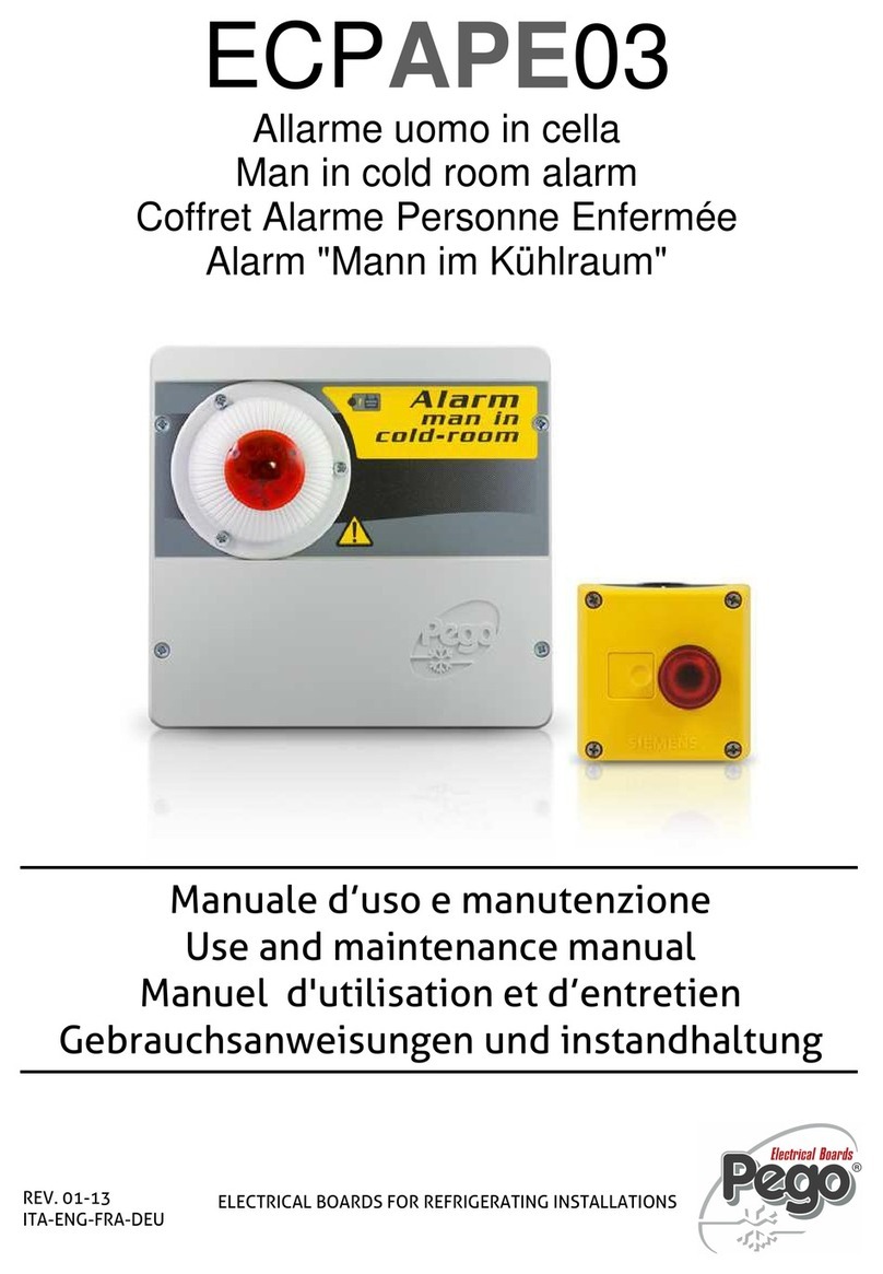
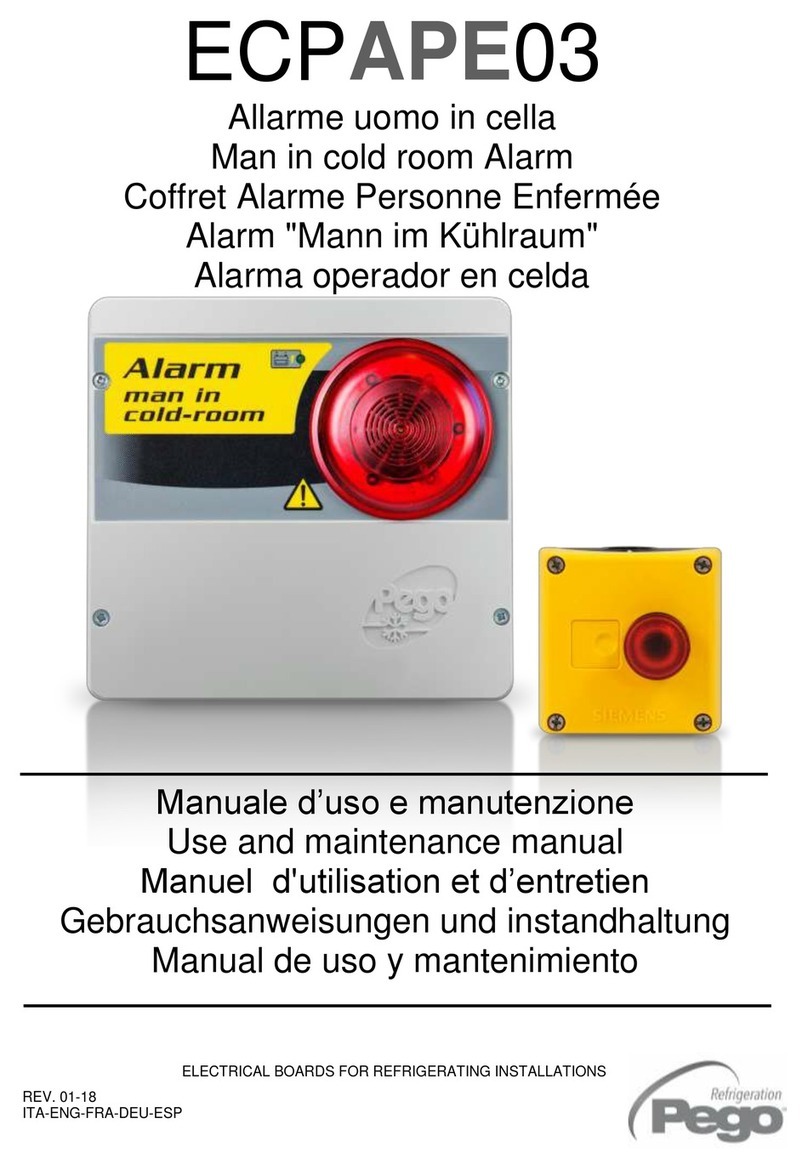
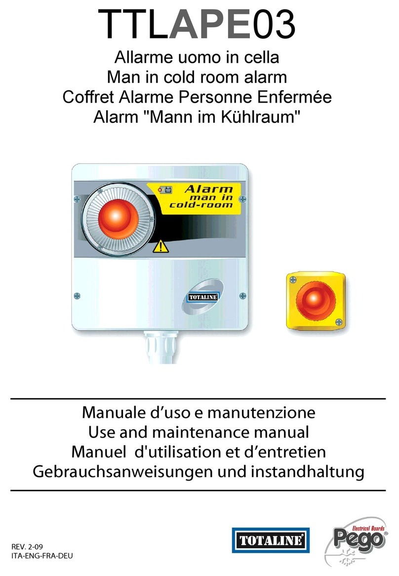
Pego ECP APE 03 User manual

V.01.01
* Alle Angaben sind ohne Gewähr, Änderungen bleiben
CI GmbH CONTROL INSTRUMENTS vorbehalten.
V-2201-001
manual
ECP APE 03

6CIAPE03
Pag.1
Rev. 1-12
INTRODUCTION
Page 21.1 MAN IN COLD ROOM ALARM KIT COMPONENTS
Page 21.2 PRODUCT IDENTIFICATION CODES
Page 21.3 TECHNICAL CHARACTERISTICS
Page 31.4 DIMENSIONS OF ALARM CONTROL UNIT
Page 31.5 DIMENSIONS OF EMERGENCY PUSHBUTTON UNIT
Page 31.6 IDENTIFICATION DATA
Page 41.7 DESCRIPTION OF SYSTEM
INSTALLATION
Page 52.1 INSTALLING THE OUT-OF-ROOM ALARM CONTROL UNIT
Page 62.2 INSTALLING THE IN-ROOM EMERGENCY PUSHBUTTON UNIT
Page 62.3 OPERATION AND MAINTENANCE
Page 72.4 EXPLODED DIAGRAM
Page 82.5 ELECTRICAL CONNECTIONS
Page 92.6 WARRANTY TERMS
APPENDICES
Page 10 A.1 EC DECLARATION OF CONFORMITY
CONTENTS
CHAP. 1
CHAP. 2
ENGLISH
- ENG -
USE AND MAINTENANCE MANUAL

6CIAPE03
Pag.2Rev. 1-12
MAN IN COLD ROOM ALARM KIT COMPONENTS
THE MAN IN COLD ROOM ALARM KIT consists of:
- Visual/acoustic alarm control unit complete with buffer battery.
- N° 3 seals, to be inserted between fixing screw and box backing.
- Emergency cold room light switch.
- Use and maintenance manual.
PRODUCT IDENTIFICATION CODE
6CIAPE03 kit complete with luminous/acoustic man in
cold room emergency alarm.
. TECHNICAL CHARACTERISTICS
Mains power supply 230 V AC 50 Hz
Max consumption on mains power 20 mA
Buffer battery 12 V DC Ni-MH 1300 mAh
Complete recharge time: 110 h
Operating autonomy - With 230 V AC NOT ON
(running on charged buffer battery) : 14 h approx.
- With 230 V AC power ON: unlimited
Out-of-room module IP 43 protection rating
Operating temperature: -5 - +45 °C
Acoustic characteristics Type: piezoelectric
Sound power: 90 dB at 1m
Visual warning Flashing red LED, 12 V DC
In-room emergency pushbutton Lighting: red LED, 12 V DC
NC contact
Keypad with IP65 protection rating
Operating temperature: -25 - +70 °C
Auxiliary relay 8A AC1 exchange contact (Relay deenergized with alarm on)
1.1
1.2
1.3
- ENG -
USE AND MAINTENANCE MANUAL
CHAPTER 1: INTRODUCTION
CHAP. 1 - Introduction

6CIAPE03
Pag.3
Rev. 1-12
DIMENSIONS OF ALARM CONTROL UNIT
DIMENSIONS OF EMERGENCY PUSHBUTTON UNIT
IDENTIFICATION DATA
The unit described in this manual has, on its side, an ID plate showing all the relevant
identification data:
• Name of Manufacturer
• Code and model of UNIT electrical board
• Serial number
• IP protection rating
• Power supply voltage
1.4
1.6
CHAP. 1 - Introduction
1.5
- ENG -
USE AND MAINTENANCE MANUAL

6CIAPE03
Pag.4Rev. 1-12
DESCRIPTION OF SYSTEM
The purpose of this safety system is to allow a person trapped inside the cold room to
activate an acoustic/luminous alarm located outside the room and so request help.
The system has been designed to function even in the event of a temporary mains power
failure: in this event the system is powered by a buffer battery housed in the external unit.
The system consists of the following parts:
•Emergency pushbutton to be fitted inside the cold room.
Consists of a luminous mushroom-type button with N.C. contact.
The pushbutton is permanently lit by LEDs so that it can be located in the dark.
•Acoustic/visual alarm control unit to be fitted outside the cold room.
Features a siren and flashing light and a buffer battery to provide power in the event
of a black-out.
There is also a clean contact (closed with alarm on) that can be used to activate
other devices such as a remote warning dialler or additional sirens.
Connection between the two devices - consisting of a lead laid by the installer as per the
wiring diagram - is ensured by the system safety logic. Should the lead be cut or
disconnected the alarm will be activated immediately.
1.7
CHAP. 1 - Introduction
- ENG -
USE AND MAINTENANCE MANUAL

6CIAPE03
Pag.5
Rev. 1-12
((
+
INSTALLING THE OUT-OF-ROOM ALARM CONTROL UNIT
1. Undo the 4 closure screws on the front panel.
2. Use the three existing holes to fix the box back panel to
the wall: use three screws of a length suitable for the
thickness of the wall to which the panel will be attached. Fit a
rubber washer (supplied) between each screw and the box
backing.
Make all the electrical connections as illustrated in the diagram for the corresponding
model (see relative table in APPENDICES). To effect correct electrical connection
and maintain the protection rating, use appropriate wire/raceway grips to ensure a
good seal. Route the wiring inside the unit in as tidy a fashion as possible: be
especially careful to keep power wires away from signal wires. Use clips to hold wires in place.
3. Re-close the front panel, making sure that all the wires are inside
the box and that the box seal sits in its seat properly.
Tighten the front panel using the 4 screws, making sure the
O-rings on the head of each screw are used.
CHAPTER 2: INSTALLATION
CHAP. 2 - Installation
2.1
- ENG -
USE AND MAINTENANCE MANUAL

6CIAPE03
Pag.6Rev. 1-12
INSTALLING THE IN-ROOM EMERGENCY PUSHBUTTON
1. The in-room pushbutton must be positioned so that it is always visible and easily
reachable.
2. Undo the two closure screws on the front of the pushbutton panel.
3. Using the two internal holes fix the box backing with three screws of a length suitable for
the thickness of the wall to which it is to be attached.
OPERATION AND MAINTENANCE
-Carry out the connections as per the wiring diagram.
-After initial connection it will take 110 hours to fully charge the battery.
-Press the luminous pushbutton installed inside the cold room to activate the acoustic
and luminous warning devices on the external alarm control unit.
The auxiliary relay contact closes.
--To deactivate the alarm, pull out the emergency illuminated push button again
(unlock)
-In the event of a 230 V AC power failure the buffer battery will intervene and power
the system for the duration indicated on the technical characteristics chart.
-Reset the emergency switch inside the cold room to cancel the alarm.
-Periodically check that the buffer battery is working properly.
-If the battery is replaced make sureit is disposed of properly at an authorised waste
collection facility.
-If the alarm is tripped without the pushbutton being pressed check the connection
lead and the connections between the pushbutton and external control unit.
SPARE PARTS:
Buffer battery: ACC12VNIMH
2.2
2.3
CHAP. 2 - Installation
- ENG -
USE AND MAINTENANCE MANUAL

6CIAPE03
Pag.7
Rev. 1-12
EXPLODED DIAGRAM
KEY
REF DESCRIPTION
1 BOX BACKING IN ABS
2 BOARD ATTACHMENT SCREWS
4 BUFFER BATTERY SUPPORT FIXING SCREWS
5 BOARD
6 BUFFER BATTERY SUPPORT METAL SHEETING
9 FRONTAL SECTION IN ABS
10 ACOUSTIC/VISUAL ALARM
11 BOX CLOSURE SCREWS
12 ACOUSTIC/VISUAL ALARM ATTACHMENT SCREWS
13 BUFFER BATTERY
CHAP. 2 - Installation
2.4
- ENG -
USE AND MAINTENANCE MANUAL

6CIAPE03
Pag.8Rev. 1-12
ELECTRICAL CONNECTIONS
Warning: The positive pole of the battery (Fastom with red wire) is initially disconnected
to maintain the charge during product storage.
Once the in-room keypad connections have been made it is, therefore, necessary to
connect this fastom to the connector marked (1) on the upper left side of the board as also
indicated on the wiring diagram.
It is advisable to first connect the control unit to the relative emergency pushbutton and
only then connect up the battery and the mains power. This will prevent activation of the
alarm.
CHAP. 2 - Installation
2.5
- ENG -
USE AND MAINTENANCE MANUAL

6CIAPE03
Pag.9
Rev. 1-12
WARRANTY TERMS
The man in cold room alarm kit is covered by a 24-month warranty against all
manufacturing defects, valid from date of delivery. If the system malfunctions as a result of
tampering, impact or improper installation the warranty will automatically be rendered null
and void. It is strongly recommended that you observe all instructions/information
regarding the technical characteristics of the device.
Any modifications made to wiring and/or internal components or any work
carried out in a way that fails to comply with the information/instructions in this
manual shall render the warranty null and void immediately.
Modifications/improper work can also cause malfunctions, irreparable damage,
serious injury or put persons/objects in danger.
PEGO S.r.l. cannot be held liable for possible errors or inaccuracies written in
this manual as a result of printing or transcription errors.
PEGO S.r.l. reserves the right to modify its products as it deems necessary
without altering its main characteristics. Each new release of a PEGO user
manual replaces previous ones.
CHAP. 2 - Installation
2.6
)
- ENG -
USE AND MAINTENANCE MANUAL

6CIAPE03
Pag.10 Rev. 1-12
EC DECLARATION OF CONFORMITY
COSTRUTTORE:
MANUFACTURER:
PEGO S.r.l. Via Piacentina, 6/b 45030 Occhiobello (RO) – Italy –
Tel. (+39) 0425 762906 Fax. (+39) 0425 762905
DENOMINAZIONE DEL PRODOTTO:
NAME OF THE PRODUCT:
MOD.: 6CIAPE03
IL PRODOTTO E’ CONFORME ALLE SEGUENTI DIRETTIVE CE:
THE PRODUCT IS IN CONFORMITY WITH THE REQUIREMENTS OF THE FOLLOWING EUROPEAN DIRECTIVES:
Direttiva Bassa Tensione (LVD): 2006/95/CE
Low voltage directive (LVD): EC/2006/95
Direttiva EMC: 2004/108/CE
Electromagnetic compatibility (EMC):EC/2004/108
LA CONFORMITA’ PRESCRITTA DALLA DIRETTIVA E’ GARANTITA DALL’ADEMPIMENTO A TUTTI GLI EFFETTI
DELLE SEGUENTI NORME (comprese tutte le modifiche):
THE CONFORMITY WITH THE REQUIREMENTS OF THIS DIRECTIVE IS TESTIFIED BY COMPLETE ADHERENCE
TO THE FOLLOWING STANDARDS (including all amendments):
Norme armonizzate: EN 60335-1, EN 378-1:2003, EN 61000-6–1, EN 61000-6–3
European standards: EN 60335-1, EN 378-1:2003, EN 61000-6–1, EN 61000-6–3
IL PRODOTTO E’ COSTITUITO PER ESSERE INCORPORATO IN UNA MACCHINA O PER ESSERE ASSEMBLATO
CON ALTRI MACCHINARI PER COSTITUIRE UNA MACCHINA CONSIDERATE DALLA DIRETTIVA: 2006/42/CE
“Direttiva Macchine”.
THE PRODUCT HAS BEEN MANUFACTURED TO BE INCLUDED IN A MACHINE OR TO BE ASSEMBLED
TOGETHER WITH OTHER MACHINERY TO COMPLETE A MACHINE ACCORDING TO DIRECTIVE: EC/2006/42
“Machinery Directive”.
Occhiobello (RO), 1/12/2011
A.1
APPENDICES
- ENG -
USE AND MAINTENANCE MANUAL
Appendicie
s
Appendicie
s

CI GmbH CONTROL INSTRUMENTS
Baumschulenweg 10 - 70736 Fellbach - DE
www.ci-gmbh.com info@ci-gmbh.com + 49 711 65883-0
This manual suits for next models
1
Table of contents
Other Pego Security System manuals
Popular Security System manuals by other brands

ADT
ADT Galaxy 8 user guide

ST Engineering Electronics
ST Engineering Electronics DigiSAFE DiskCrypt M10 user manual

Super Circuits
Super Circuits BLK-SY10 Series Systems Setup guide

Honeywell
Honeywell PID-95P Quck Start Guide

Entrya
Entrya ET2000 quick start guide

Sabik Marine
Sabik Marine Vega VLB-44X Series product manual

Silent Alert
Silent Alert CL4A-2212-EU quick start guide

ZETRON
ZETRON 025-9581M Installation and Maintenance

Western Digital
Western Digital ReadyView WDBULT0020HWT-HESN user manual

ABC Office
ABC Office Vector 06502 user guide

Nortel
Nortel CallPilot 100 Administration guide

ADEMCO
ADEMCO VISTA-20P Series user guide