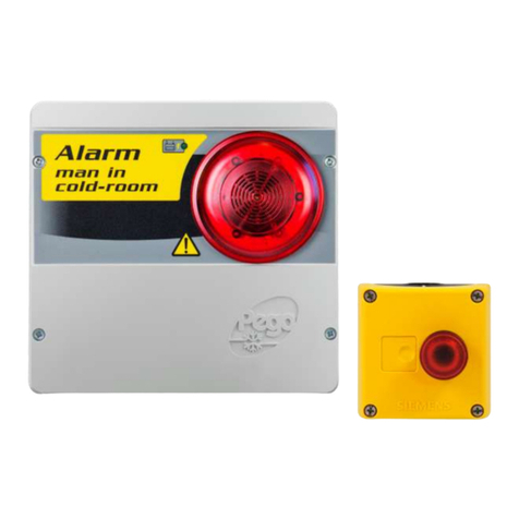
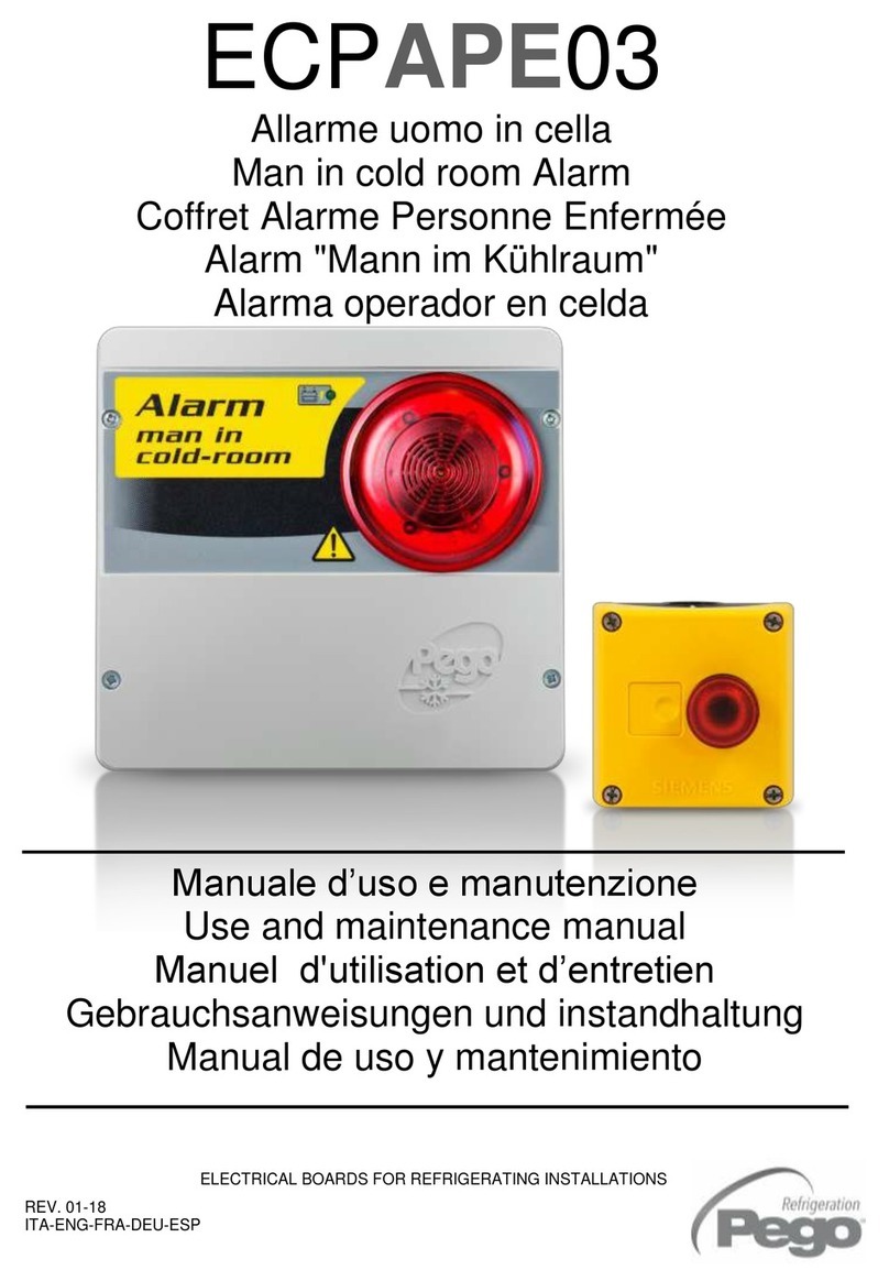
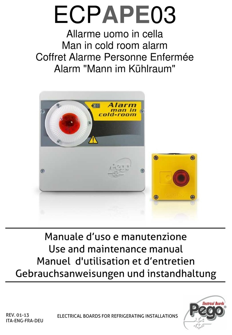
Pego TOTALINE Man in cold room alarm User manual

Manuale d’uso e manutenzione
Use and maintenance manual
Manuel d'utilisation et d’entretien
Gebrauchsanweisungen und instandhaltung
REV. 2-09
ITA-ENG-FRA-DEU
TTLAPE03
Allarme uomo in cella
Man in cold room alarm
Coffret Alarme Personne Enfermée
Alarm "Mann im Kühlraum"

TTLAPE03
Pag. 2 Rev. 2-09

TTLAPE03
Pag.3
Rev. 2-09
INTRODUZIONE
Pag. 4 1.1 COMPONENTI DEL KIT ALLARME UOMO IN CELLA
Pag. 4 1.2 CODICE IDENTIFICAZIONE PRODOTTI
Pag. 4 1.3 CARATTERISTICHE TECNICHE
Pag. 5 1.4 DIMENSIONI D’INGOMBRO CENTRALINA DI GESTIONE ALLARME
Pag. 5 1.5 DIMENSIONI D’INGOMBRO PULSANTIERA DI EMERGENZA
Pag. 5 1.6 DATI DI IDENTIFICAZIONE
Pag. 6 1.7 DESCRIZIONE DEL SISTEMA
INSTALLAZIONE
Pag. 7 2.1 INSTALLAZIONE CENTRALINA DI GESTIONE ALLARME ESTERNO CELLA
Pag. 8 2.2 INSTALLAZIONE PULSANTIERA DI EMERGENZA INTERNO CELLA
Pag. 8 2.3 FUNZIONAMENTO E MANUTENZIONE
Pag. 9 2.4 ESPLOSO
Pag. 10 2.5 COLLEGAMENTI ELETTRICI
Pag. 11 2.6 CONDIZIONI DI GARANZIA
ALLEGATI
Pag. 12 A.1 DICHIARAZIONE DI CONFORMITA’ CE
INDICE
CAP. 1
CAP. 2
- ITA -
ITALIANO
- ITA -
MANUALE D’USO E MANUTENZIONE

TTLAPE03
Pag. 4 Rev. 2-09
COMPONENTI DEL KIT ALLARME UOMO IN CELLA
Il KIT ALLARME UOMO IN CELLA è costituito da:
- Centralina di gestione allarme visivo acustico completa di batteria tampone.
- N° 3 guarnizioni di tenuta, da interporre tra la vite di fissaggio ed il fondo scatola.
- Pulsante luminoso di emergenza interno cella.
- Manuale d’uso e manutenzione.
CODICE IDENTIFICAZIONE PRODOTTI
TTLAPE03 kit completo di segnalazione acustico
luminosa per emergenza uomo in cella.
. CARATTERISTICHE TECNICHE
Alimentazione principale 230 Vac 50 Hz
Consumo max su alim. principale 20 mA
Batteria tampone 12 VDC Ni-MH 1300 mAh
Tempo di ricarica completo: 110 h
Autonomia di funzionamento - Con alimentazione 230Vac NON presente
(funzionamento con Batteria tampone carica) : 14 h Circa
- Con alimentazione 230Vac presente: illimitato
Modulo esterno cella Grado di protezione IP 43
Temperatura di funzionamento: -5 ÷+45 °C
Caratteristiche acustiche
Tipo: piezoelettrico
Potenza sonora: 90 dB a 1m
Segnalazione visiva A LED lampeggiante rosso 12 Vdc
Pulsante di emergenza interno cella Illuminazione: LED rosso 12 Vdc
Contatto NC
Pulsantiera con grado di protezione IP65
Temperatura di funzionamento: -25 ÷+70 °C
Relè ausiliario 8A AC1 (Il contatto chiude con allarme inserito)
CAPITOLO 1 : INTRODUZIONE
CAP. 1 - Introduzion
e
1.1
1.2
1.3
- ITA -
MANUALE D’USO E MANUTENZIONE

TTLAPE03
Pag.5
Rev. 2-09
DIMENSIONI D’INGOMBRO CENTRALINA DI GESTIONE ALLARME
DIMENSIONI D’INGOMBRO PULSANTIERA DI EMERGENZA
DATI DI IDENTIFICAZIONE
L’apparecchio descritto sul presente manuale è provvisto sul lato di una targhetta
riportante i dati d’identificazione dello stesso:
• Nome del Costruttore
• Codice e modello quadro elettrico dell’apparecchio
• Matricola
• Grado di protezione IP
• Tensione di alimentazione
1.4
1.6
CAP. 1 - Introduzione
1.5
MANUALE D’USO E MANUTENZIONE
- ITA -
85
85
60

TTLAPE03
Pag. 6 Rev. 2-09
DESCRIZIONE DEL SISTEMA
Questo sistema di sicurezza ha lo scopo di permettere a una persona rimasta bloccata
all’interno della cella di attivare un segnale di allarme acustico luminoso presente
all’esterno della stessa per richiedere soccorso.
Il sistema è studiato per il funzionamento anche in caso di temporaneo black-out della rete
elettrica grazie ad una batteria tampone contenuta nell’unità esterna.
Le parti che lo compongono sono le seguenti:
• Pulsantiera di emergenza da montare all’interno della cella.
Essa è composta da un fungo luminoso con contatto N.C.
L’illuminazione del fungo, realizzata mediante LED, è permanente per renderne
possibile l’individuazione anche al buio.
• Centralina di gestione allarme visivo acustico da montare all’esterno della
cella.
Essa è dotata di una sirena ed un lampeggiante per la segnalazione dell’allarme e
di una batteria tampone in caso di black-out.
E’ inoltre presente un contatto pulito (chiuso con allarme attivo) che può essere
utilizzato per attivare ulteriori dispositivi come per esempio un combinatore
telefonico per la segnalazione remota di allarme o sirene aggiuntive.
Il collegamento fra i due dispositivi ,che consiste in un cavo posato e collegato
dall’installatore seguendo lo schema elettrico di collegamento , è garantito dalla logica in
sicurezza del sistema. Se il cavo venisse tagliato o scollegato si avrebbe infatti l’immediata
attivazione dell’allarme.
1.7
CAP. 1 - Introduzion
e
- ITA -
MANUALE D’USO E MANUTENZIONE

TTLAPE03
Pag.7
Rev. 2-09
INSTALLAZIONE CENTRALINA DI GESTIONE ALLARME ESTERNO CELLA
1. Svitare le 4 viti di chiusura presenti sul frontale.
2. Utilizzando i tre fori preesistenti fissare il fondo della
scatola tramite tre viti di adeguata lunghezza in relazione
allo spessore della parete su cui fissare il quadro. Interporre
tra ogni vite di fissaggio ed il fondo della scatola una rondella
in gomma (fornita).
Effettuare tutti i collegamenti elettrici secondo gli schemi allegati per il modello corrispondente
(vedi le relative tabelle in ALLEGATI). Per effettuare i collegamenti elettrici in modo affidabile e
mantenere il grado di protezione della scatola si consiglia di utilizzare opportuni pressacavi e/o
pressatubi per serrare a tenuta tutti i cablaggi. Si consiglia di distribuire il passaggio dei conduttori
all’interno del quadro il più ordinato possibile, in particolar modo tenere lontano i conduttori di
potenza da quelli di segnale. Utilizzare eventuali fascette di tenuta.
3. Richiudere il coperchio frontale, ponendo attenzione che
tutti i cavi siano all’interno della scatola e che la guarnizione
della scatola sia correttamente alloggiata nella propria sede.
Serrare il coperchio frontale con le 4 viti, riutilizzando gli O-
ring presenti sulla gola di ciascuna vite.
CAPITOLO 2: INSTALLAZIONE
CAP. 2 - Installazione
2.1
- ITA -
MANUALE D’USO E MANUTENZIONE

TTLAPE03
Pag. 8 Rev. 2-09
INSTALLAZIONE PULSANTIERA DI EMERGENZA INTERNO CELLA
1. Il pulsante all’interno della cella dovrà essere posizionato in modo da essere sempre
visibile e facilmente raggiungibile.
2. Svitare le due viti di chiusura presenti sul frontale della pulsantiera.
3. Utilizzando i due fori presistenti all’interno fissare il fondo della pulsantiera tramite tre viti
di adeguata lunghezza in relazione allo spessore della parete di fissaggio.
FUNZIONAMENTO E MANUTENZIONE
- Eseguire i collegamenti elettrici come da schema.
- Al primo collegamento sono necessarie 110 ore per assicurare la completa carica
delle batterie.
- Premere il pulsante luminoso installato all’interno della cella per attivare la
segnalazione acustica e luminosa della centralina esterna di gestione allarme.
Il contatto del relè ausiliario si chiude.
- In caso di interruzione dell’alimentazione 230 Vac interverrà la batteria tampone per
mantenere attivo il sistema per la durata indicata nelle caratteristiche tecniche.
- Ripristinare il contatto di emergenza all’interno della cella per terminare la
segnalazione d’allarme.
- Verificare periodicamente l’efficienza della batteria tampone.
- In caso di sostituzione della batteria tampone non cestinare ma utilizzare gli
appositi centri di raccolta per un coretto smaltimento.
- Nel caso si attivi l’allarme anche con pulsante di emergenza non premuto verificare
l’integrità del cavo e dei collegamenti fra pulsante e centralina esterna.
RICAMBI:
Batteria tampone: ACC12VNIMH
2.2
2.3
CAP. 2 - Installazion
e
- ITA -
MANUALE D’USO E MANUTENZIONE

TTLAPE03
Pag.9
Rev. 2-09
ESPLOSO
LEGENDA
RIF DESCRIZIONE
1 SCATOLA POSTERIORE IN ABS
2 VITI FISSAGGIO SCHEDA
4 VITI DI FISSAGGIO SUPPORTO BATTERIA TAMPONE
5 SCHEDA
6 LAMIERA DI SUPPORTO BATTERIA TAMPONE
9 SCATOLA FRONTALE IN ABS
10 ALLARME SONORO E VISIVO
11 VITI CHIUSURA SCATOLA
12 VITI FISSAGGIO ALLARME SONORO E VISIVO
13 BATTERIA TAMPONE
CAP. 2 - Installazione
2.4
- ITA -
MANUALE D’USO E MANUTENZIONE

TTLAPE03
Pag. 10 Rev. 2-09
COLLEGAMENTI ELETTRICI
Attenzione : Il polo positivo della batteria (Fastom con cavo rosso) è inizialmente
scollegato per mantenere la carica della stessa durante la fase di stoccaggio prodotto.
E’ quindi necessario, una volta eseguiti i collegamenti elettrici con la pulsantiera interno
cella, collegare tale fastom al connettore contrassegnato con (1) presente sul lato alto
sinistro della scheda come risulta anche dalla tarche dallo schema elettrico.
Si suggerisce di collegare prima la centralina alla relativa pulsantiera di emergenza e solo
successivamente connettere la batteria e l’alimentazione di rete. Questo per evitare
l’attivazione del segnale di allarme.
CAP. 2 - Installazion
e
2.5
- ITA -
MANUALE D’USO E MANUTENZIONE

TTLAPE03
Pag.11
Rev. 2-09
CONDIZIONI DI GARANZIA
Il kit allarme uomo in cella è coperto da garanzia contro tutti i difetti di fabbricazione per 24
mesi dalla data di consegna. Il cattivo funzionamento causato da manomissioni, urti,
inadeguata installazione fa decadere automaticamente la garanzia. Si raccomanda
vivamente di rispettare tutte le caratteristiche tecniche di esercizio dell’apparecchio.
ATTENZIONE !
Interventi che modifichino il cablaggio elettrico e/o i componenti interni eseguito
in modo non conforme a quanto illustrato su questo manuale, oltre a far
decadere immediatamente la garanzia, possono causare guasti irreparabili,
cattivo funzionamento o generare situazioni di grave pericolo per le persone o
per le cose.
PEGO S.r.l. declina ogni responsabilità per le possibili inesattezze contenute
nel presente manuale, se dovute ad errori di stampa o di trascrizione.
PEGO S.r.l. si riserva il diritto di apportare ai propri prodotti quelle modifiche
che riterrà necessarie o utili, senza pregiudicarne le caratteristiche essenziali.
Ogni nuova release dei manuali dei prodotti PEGO sostituisce tutte le
precedenti.
CAP. 2 - Installazione
2.6
)
- ITA -
MANUALE D’USO E MANUTENZIONE

TTLAPE03
Pag. 12 Rev. 2-09
DICHIARAZIONE DI CONFORMITA’ CE
COSTRUTTORE / MANUFACTURER
PEGO SRL Via Piacentina,6b 45030 Occhiobello (RO) - ITALY -
DENOMINAZIONE DEL PRODOTTO / NAME OF THE PRODUCT
MOD.: TTLAPE03
IL PRODOTTO E’ CONFORME ALLE SEGUENTI DIRETTIVE CE/THE PRODUCT IS
IN CONFORMITY WITH THE REQUIREMENTS OF THE FOLLOWING EUROPEAN
DIRECTIVES:
2006/95/CE Direttiva del Consiglio per l’unificazione delle normative dei Paesi CEE relativa al
materiale elettrico destinato ad essere utilizzato entro certi limiti di tensione e
successive modificazioni
2006/95/EC Concil Directive on the approximation of the laws of the Member States relating to
electrical equipments employed within certain limits of tension and following modifications
2004/108/CE Direttiva del Consiglio per l’unificazione delle normative dei Paesi CEE relativa
alla compatibilità elettromagnetica e successive modificazioni
2004/108/EC Concil Directive on the approximation of the laws of the Member States relating to the
electro-magnetical compatibility and following modifications
93/68 CEE Direttiva del consiglio per la marcatura CE del materiale elettrico destinato ad essere
utilizzato entro talunni limiti di tensione.
93/68 EEC Council Directive for the CE marking of electrical materials to be used within certain limits of
voltage.
LA CONFORMITA’ PRESCRITTA DALLE DIRETTIVE E’ GARANTITA DALL’
ADEMPIMENTO A TUTTI GLI EFFETTI DELLE SEGUENTI NORME:
CONFORMITY WITH THE REQUIREMENTS OF THIS DIRECTIVE IS TESTIFIED
BY COMPLETE ADHRENCE TO THE FOLLOWING STANDARDS:
NORMES HARMONISÉES / HARMONIZED EUROPEAN STANDARDS
EN 61000-6–1 EN 61000-6–3 EN 60335 – 1 EN 378-1:2000
II Edition II Edition
A.1
ALLEGATI
- ITA -
MANUALE D’USO E MANUTENZIONE
Allegat
i

TTLAPE03
Pag.13
Rev. 2-09
INTRODUCTION
Page 14 1.1 MAN IN COLD ROOM ALARM KIT COMPONENTS
Page 14 1.2 PRODUCT IDENTIFICATION CODES
Page 14 1.3 TECHNICAL CHARACTERISTICS
Page 15 1.4 DIMENSIONS OF ALARM CONTROL UNIT
Page 15 1.5 DIMENSIONS OF EMERGENCY PUSHBUTTON UNIT
Page 15 1.6 IDENTIFICATION DATA
Page 16 1.7 DESCRIPTION OF SYSTEM
INSTALLATION
Page 17 2.1 INSTALLING THE OUT-OF-ROOM ALARM CONTROL UNIT
Page 18 2.2 INSTALLING THE IN-ROOM EMERGENCY PUSHBUTTON UNIT
Page 18 2.3 OPERATION AND MAINTENANCE
Page 19 2.4 EXPLODED DIAGRAM
Page 20 2.5 ELECTRICAL CONNECTIONS
Page 21 2.6 WARRANTY TERMS
APPENDICES
Page 22 A.1 EC DECLARATION OF CONFORMITY
CONTENTS
CHAP. 1
CHAP. 2
ENGLISH
- ENG -
USE AND MAINTENANCE MANUAL

TTLAPE03
Pag.14 Rev. 2-09
MAN IN COLD ROOM ALARM KIT COMPONENTS
THE MAN IN COLD ROOM ALARM KIT consists of:
- Visual/acoustic alarm control unit complete with buffer battery.
- N° 3 seals, to be inserted between fixing screw and box backing.
- Emergency cold room light switch.
- Use and maintenance manual.
PRODUCT IDENTIFICATION CODE
TTLAPE03 kit complete with luminous/acoustic man in
cold room emergency alarm.
. TECHNICAL CHARACTERISTICS
Mains power supply 230 V AC 50 Hz
Max consumption on mains power 20 mA
Buffer battery 12 V DC Ni-MH 1300 mAh
Complete recharge time: 110 h
Operating autonomy - With 230 V AC NOT ON
(running on charged buffer battery) : 14 h approx.
- With 230 V AC power ON: unlimited
Out-of-room module IP 43 protection rating
Operating temperature: -5 - +45 °C
Acoustic characteristics
Type: piezoelectric
Sound power: 90 dB at 1m
Visual warning Flashing red LED, 12 V DC
In-room emergency pushbutton Lighting: red LED, 12 V DC
NC contact
Keypad with IP65 protection rating
Operating temperature: -25 - +70 °C
Auxiliary relay 8A AC1 (contact closes with alarm on)
1.1
1.2
1.3
- ENG -
USE AND MAINTENANCE MANUAL
CHAPTER 1: INTRODUCTION
CHAP. 1 - Introduction

TTLAPE03
Pag.15
Rev. 2-09
DIMENSIONS OF ALARM CONTROL UNIT
DIMENSIONS OF EMERGENCY PUSHBUTTON UNIT
IDENTIFICATION DATA
The unit described in this manual has, on its side, an ID plate showing all the relevant
identification data:
• Name of Manufacturer
• Code and model of UNIT electrical board
• Serial number
• IP protection rating
• Power supply voltage
1.4
1.6
CHAP. 1 - Introduction
1.5
- ENG -
USE AND MAINTENANCE MANUAL
85
85
60

TTLAPE03
Pag.16 Rev. 2-09
DESCRIPTION OF SYSTEM
The purpose of this safety system is to allow a person trapped inside the cold room to
activate an acoustic/luminous alarm located outside the room and so request help.
The system has been designed to function even in the event of a temporary mains power
failure: in this event the system is powered by a buffer battery housed in the external unit.
The system consists of the following parts:
• Emergency pushbutton to be fitted inside the cold room.
Consists of a luminous mushroom-type button with N.C. contact.
The pushbutton is permanently lit by LEDs so that it can be located in the dark.
• Acoustic/visual alarm control unit to be fitted outside the cold room.
Features a siren and flashing light and a buffer battery to provide power in the event
of a black-out.
There is also a clean contact (closed with alarm on) that can be used to activate
other devices such as a remote warning dialler or additional sirens.
Connection between the two devices - consisting of a lead laid by the installer as per the
wiring diagram - is ensured by the system safety logic. Should the lead be cut or
disconnected the alarm will be activated immediately.
1.7
CHAP. 1 - Introduction
- ENG -
USE AND MAINTENANCE MANUAL

TTLAPE03
Pag.17
Rev. 2-09
((
+
INSTALLING THE OUT-OF-ROOM ALARM CONTROL UNIT
1. Undo the 4 closure screws on the front panel.
2. Use the three existing holes to fix the box back panel to
the wall: use three screws of a length suitable for the
thickness of the wall to which the panel will be attached. Fit a
rubber washer (supplied) between each screw and the box
backing.
Make all the electrical connections as illustrated in the diagram for the corresponding
model (see relative table in APPENDICES). To effect correct electrical connection
and maintain the protection rating, use appropriate wire/raceway grips to ensure a
good seal. Route the wiring inside the unit in as tidy a fashion as possible: be
especially careful to keep power wires away from signal wires. Use clips to hold wires in place.
3. Re-close the front panel, making sure that all the wires are inside
the box and that the box seal sits in its seat properly.
Tighten the front panel using the 4 screws, making sure the
O-rings on the head of each screw are used.
CHAPTER 2: INSTALLATION
CHAP. 2 - Installation
2.1
- ENG -
USE AND MAINTENANCE MANUAL

TTLAPE03
Pag.18 Rev. 2-09
INSTALLING THE IN-ROOM EMERGENCY PUSHBUTTON
1. The in-room pushbutton must be positioned so that it is always visible and easily
reachable.
2. Undo the two closure screws on the front of the pushbutton panel.
3. Using the two internal holes fix the box backing with three screws of a length suitable for
the thickness of the wall to which it is to be attached.
OPERATION AND MAINTENANCE
- Carry out the connections as per the wiring diagram.
- After initial connection it will take 110 hours to fully charge the battery.
- Press the luminous pushbutton installed inside the cold room to activate the
acoustic and luminous warning devices on the external alarm control unit.
The auxiliary relay contact closes.
- In the event of a 230 V AC power failure the buffer battery will intervene and power
the system for the duration indicated on the technical characteristics chart.
- Reset the emergency switch inside the cold room to cancel the alarm.
- Periodically check that the buffer battery is working properly.
- If the battery is replaced make sure it is disposed of properly at an authorised waste
collection facility.
- If the alarm is tripped without the pushbutton being pressed check the connection
lead and the connections between the pushbutton and external control unit.
SPARE PARTS:
Buffer battery: ACC12VNIMH
2.2
2.3
CHAP. 2 - Installation
- ENG -
USE AND MAINTENANCE MANUAL

TTLAPE03
Pag.19
Rev. 2-09
EXPLODED DIAGRAM
KEY
REF DESCRIPTION
1 BOX BACKING IN ABS
2 BOARD ATTACHMENT SCREWS
4 BUFFER BATTERY SUPPORT FIXING SCREWS
5 BOARD
6 BUFFER BATTERY SUPPORT METAL SHEETING
9 FRONTAL SECTION IN ABS
10 ACOUSTIC/VISUAL ALARM
11 BOX CLOSURE SCREWS
12 ACOUSTIC/VISUAL ALARM ATTACHMENT SCREWS
13 BUFFER BATTERY
CHAP. 2 - Installation
2.4
- ENG -
USE AND MAINTENANCE MANUAL

TTLAPE03
Pag.20 Rev. 2-09
ELECTRICAL CONNECTIONS
Warning: The positive pole of the battery (Fastom with red wire) is initially disconnected
to maintain the charge during product storage.
Once the in-room keypad connections have been made it is, therefore, necessary to
connect this fastom to the connector marked (1) on the upper left side of the board as also
indicated on the wiring diagram.
It is advisable to first connect the control unit to the relative emergency pushbutton and
only then connect up the battery and the mains power. This will prevent activation of the
alarm.
CHAP. 2 - Installation
2.5
- ENG -
USE AND MAINTENANCE MANUAL
This manual suits for next models
1
Table of contents
Languages:
Other Pego Security System manuals
Popular Security System manuals by other brands

Chamberlain
Chamberlain 8747AML quick start guide

minirookmelder
minirookmelder MH3120 installation instructions

Toa
Toa RS-150 operating instructions

DSC
DSC PC2580 instruction manual

Cypress Semiconductor
Cypress Semiconductor CapSense CPSoC Specification sheet

Jet
Jet LOAD-N-LOCK JT1-125 installation manual