pela tools BDS69 User manual

Bandputsmaskin
Belt & Disc sander
BDS69
Item No:
50619

13. HÅLL VERKTYGET I GOTT SKICK. Håll verktygen
skarpa och rena för bästa och säkraste prestanda.
Följinstruktionerna för smörjning och byte av tillbehör.
14. KOPPLA BORT VERKTYGET före service vid byte av
tillbehör som blad.
15. REDUCERA RISKEN FÖR OAVSIKTLIG START. Se till
att strömställaren är avstängd Innan verktyget pluggas in.
16. ANVÄND REKOMMENDERADE TILLBEHÖR. Se
bruksanvisningen för rekommenderadE tillbehör.
Användning av felaktiga tillbehör kan medföra risk för
personskador.
17. STÅ ALDRIG PÅ VERKTYGET. Allvarlig skada kan
uppstå om verktyget tippas eller om skärverktyget
vidrörs oavsiktligt.
18. KONTROLLERA SKADADE DELAR. Före ytterligare
användning av verktyget, bör ett skydd till någon del som
är skadat kontrolleras noggrant för att bestämma om den
fungerar korrekt och utför det den är avsedd för. Gör en
funktions-kontroll för inriktning av rörliga delar, bindning
av rörliga delar, brott på delar, montering och andra villkor
som kan påverka dess funktion. Ett skydd eller annan del
som är skadat ska repareras eller bytas ut.
19. RIKTNING PÅ INMATNING. För alltid arbetsstycket
in i ett blad eller skär MOT rotationsriktningen av bladet
eller skäraren.
20. LÄMNA ALDRIG VERKTYGET I GÅNG UTAN
UPPSYN. Stäng av strömmen. Lämna inte verktyget tills
det kommer till ett fullständigt stopp.
Kontaktinformation
Verktygsboden Erlux AB
Källbäcksrydsgatan 1
SE-507 42 Borås
Telefon: 033-202650
Mejl: [email protected]
Miljöskydd/Skrotning
Återvinn oönskat material, släng
det inte bland hushållssoporna. Alla
maskiner, tillbehör och förpackningar
skall sorteras och lämnas till en
återvinningscentral och där kasseras på ett
miljövänligt sätt.
Säkerhetsregler
1. HÅLL SKYDD PÅ PLATS och i god kondition.
2. AVLÄGSNA JUSTERINGSNYCKLAR OCH NYCKLAR.
Görtill vana att kontrollera att nycklar och justeringsnycklar
tas bort från verktyget innan de slås på.
3. HÅLL ARBETSOMRÅDET RENT. Röriga områden och
bänkar bjuder in till olyckor.
4. ANVÄND INTE I FARLIG MILJÖ. Använd inte elverktyg
på i fuktig eller våt plats eller exponera dem för regn.
Håll arbets-området väl upplyst.
5. HÅLL BARN BORTA. Alla besökare bör hållas på
säkert avstånd från arbetsområdet.
6. GÖR JOBBET BARNSÄKERT med hänglås,
huvudbrytare eller genom att ta bort startknappar.
7. STRESSA INTE VERKTYGET. Det kommer att göra
jobbet bättre och säkrare om det används i den takt det
var designat för.
8. TVINGA INTE VERKTYGET eller tillbehöret att göra ett
jobb för vilket det inte var konstruerat.
9. BÄR LÄMPLIG UTSTYRSEL. Inga lösa kläder, handskar,
slipsar, ringar, armband eller andra smycken som fångas
i rörliga delar. Halkfria skor rekommenderas. Använd
skyddande hårbeklädnad för att skydda långt hår.
10. ANVÄND ALTID SÄKERHETSGLASÖGON. Använd
också ansikts- eller damm-mask om slipningen är
dammig. Vardagliga glasögon har bara slagtåliga linser,
de är INTE skyddsglasögon.
11. SÄKERT ARBETE. Använd klämmor eller en skruv för
att hålla arbetet när det är praktiskt. Det är säkrare än att
använda din hand och det frigör båda händerna för att
använda verktyget.
12. STRÄCK DIG INTE ÖVER. Håll rätt fot och balans hela
tiden.
Särskilda säkerhetsregler för
putsmaskin
1. Använd skyddsglasögon.
2. Stöd arbetsstycke med backstop eller arbetsbord.
3. Behåll 1/16 tums maximalt utrymme mellan bord och
slipband eller skiva.
4. Håll arbetet ordentligt så att det inte glider ur dina
händer.
5. Tryck inte på bältet under drift. För mycket tryck mot
bältet är aldrig nödvändigt. Det kommer endast att leda
till skador på bältet eller arbetsstycket.
6. I hemmet där det nns små barn är det bra att koppla
loss motorn och ta bort bältet när verktyget inte är i drift.
7. Mata arbetsstycket mot slipens rotation.
8. Anslut till en matningskrets som skyddas av en
strömbrytare eller tidsfördröjningssäkring.
9. Fäst verktygets bas till golv innan du startar.
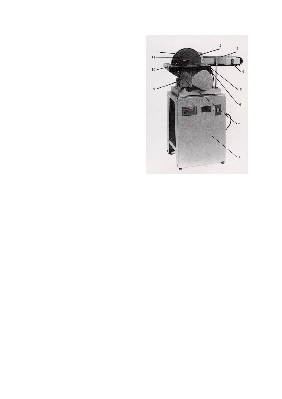
Ditt verktyg
1. Skivskyddet 2. Backstop 3. Skyddsrem
4. Justera ratten 5. Arbetsbord 6. Motor
7. Bordsförhållare 8. Stativplatta 9. Knopp
10. Vinkelmätare 11. Slipskiva

Dekaler och varningssymboler
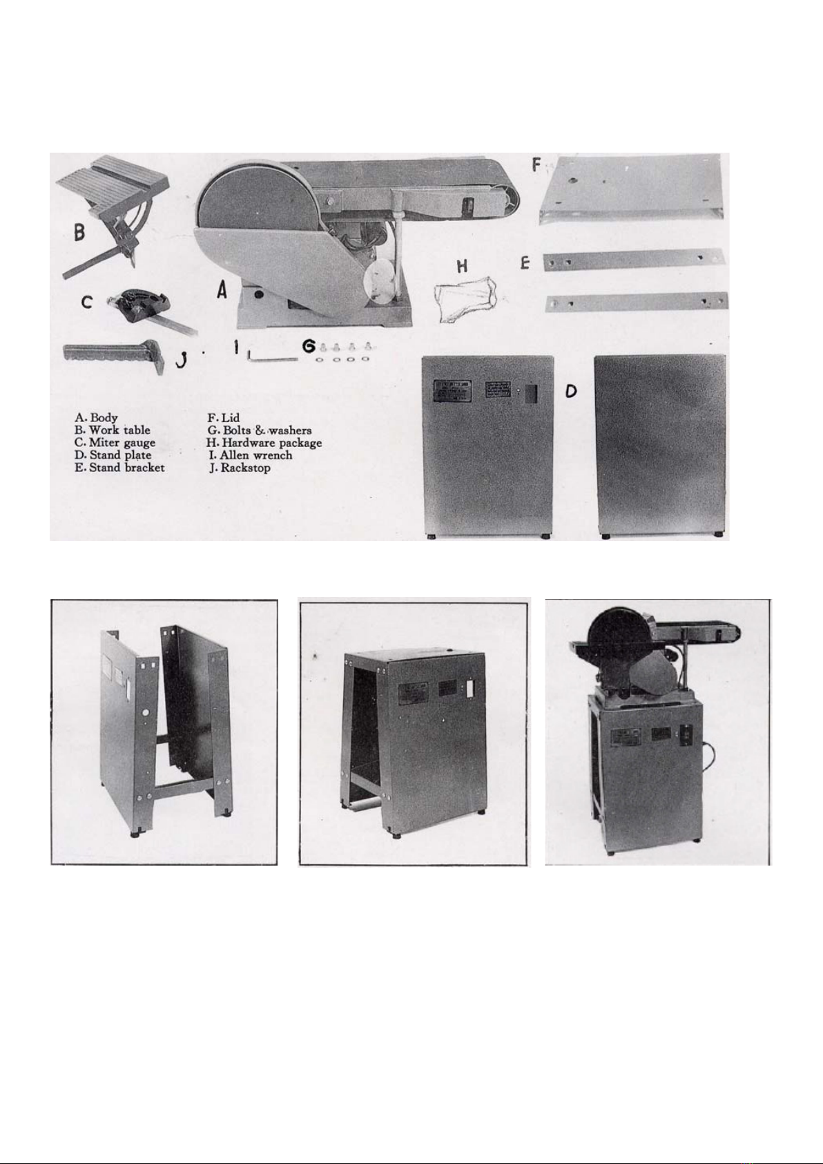
Uppackning
Packa försiktigt upp verktyget och kontrollera alla föremål. Figur 2 illustrerar innehållet i kartongen. Kassera inte
förpackningsmaterial tills verktyget är helt monterad och i funktion.
Montering
Fig.3
Montering av benstativ.
1. När du börjar montera
benstativet, montera de två stativen
(D) och två konsoler (E) tillsammans
så som visas i Fig. 3. Skruvar och
muttrar nns i ditt förpackningen.
Dra inte åt skruvarna först, utan dra
dem när du har slutfört enheten.
Fig.4
2. När du avslutat med g.3 fortsätt
till g.4 och lägg locket (F) på
stativet och dra åt alla skruvar.
Fig 5.
Montering av stativ och kropp
Placera kroppen på stativet, kom
ihåg att ha de fyra hålen på locket
på rätt sätt och i läge för att ansluta
till de fyra gängade hålen på
kroppen. Ta ut bultar och brickor
(G) från förpackningen för att dra åt
stativet och kropp som g 5.

Fig 6.
Montering av backstopp
Montera backstoppet på kroppen som visas i Fig.6. och
kom ihåg att dra åt skruven. Denna backstopp kan hålla
dig säkrare vid slipning.
Fig 7.
Montering av arbetsbord
Lossa xeringsskruven som i g. 7. Sätt in plattans stav
i hålet, men kom ihåg att ha den plana ytan på axeln
mot xerings-skruven. Dra åt skruven så att du har
ett utrymme på 1/16" (13mm) kvar mellan bordet och
slipskivan.
Fig 8.
Horisontell och spännings-justering av slipband
Om du upptäcker att slipbältet är för hårt, för löst eller
till och med inte ordentligt inriktad centralt, använd
insexnyckeln för att justera justeringsvredet till rätt
spänning du behöver. Se Fig.8.
Fig 9.
Byte av slipband
Upprepa samma procedur som i Fig.8. Lossa bältet och
ta ut det gamla bältet. Efter att bytt ut ett nytt bälte, se
till att bältet har rätt spänning. Se g. 9.
Fig 10.
Slippapper och byte av kilrem
1. Lossa vredet och öppna skivskyddet enligt bild 10.

Fig 11.
2. Riva av det gamla slippappret, rengör limrester som
är kvar på skivan och sätt på det nya slippapperet som i
g.11.
Fig 12,
3. Använd insexnyckeln som visas i Fig.12, Sätt in
skift-nyckeln i rektangulära fönstret längst ner på
skivskyddet. Lossa skruven inuti och ta av slipskivan.
När du ska sätta tillbaka skivan, kom ihåg att skruven
måste monteras på axelns atsida och dras åt.
Justering av bord från 0 ° -45 °
Lossa vredet och justera bordet tills det når skalan du
efterfrågar (varierar från 0 ° -45 °) och dra åt.
Fig 14.
Justering av slipband.
Lossa de båda muttrarna enligt g.14. (som visas i guren
kan du bara se en mutter, en annan är nertill nedanför
längst ner på skivskyddet, följ pilinstruktionen). När du har
lossat muttrarna kan du dra upp bältet i vertikalt läge och
dra åt muttrarna innan du fortsätter arbetet.
Fig 15.
Ändring av bordets position
När bältet är i vertikalt läge kan du ytta bordet till
bältets framsida. Först av allt, lossa skruven och ytta
till positionen som i Fig.15. Dra åt skruven men notera
mellanrummet på 3mm mellan bältet och bordet.
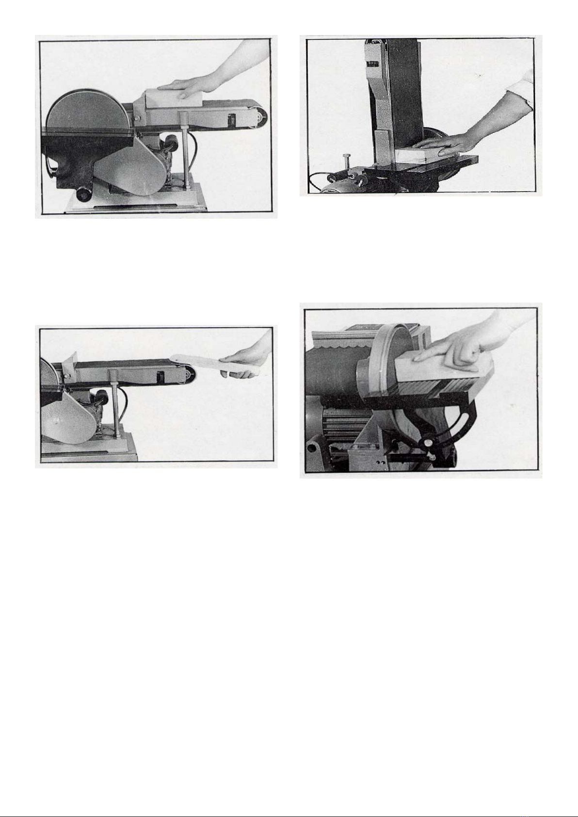
Fig 16.
Horisontell slipning
Sätt ditt arbetsstycke på bältet och hjälp med bakstoppet
xera arbetsstycket. Var försiktig när du startar driften.
Tryck inte på för hårt på arbetsstycket, eftersom bältet
fungerar bättre om man inte överdriver jobbet. Fig.16.
Fig 17.
Kurvslipning
Använd bältesänden för att hjälpa din kurvslipning som
visas i gur 17.
Fig 18.
Vertikal slipning
När bältet är i vertikalt läge, använd bakstoppet
för att hålla arbetsstycket, eller kan du ändra
arbetsbordsställning som visas i g.15 för att hjälpa
slipningen. Se Fig.18
Fig 19.
Horisontell slipning med skivan.
Sätt arbetsstycket på arbetsbordet enligt g.19. Och
börja ditt sliparbete. Detta är lämpligt för slipning av
små ytor.

Fig 20.
Skalad slipning från 0 ° -45 ° av arbetsbordet
Ditt arbetsbord kan göra slipning från 0 ° -45 ° som visas
i Fig.20. Efter justering var noga med att dra åt skruven
för att inte påverka din säkerhet och precisionsslipning.
Fig 21.
Vridning av 0 ° -60 ° från vänster tillhöger
Använd vinkelmätaren för att arbeta med bordet och
du kan få vinkelslipning från 0 ° -60 ° som i Fig.21.
Var försiktig med att vredet vrids efter justering av
vinkelmätaren.
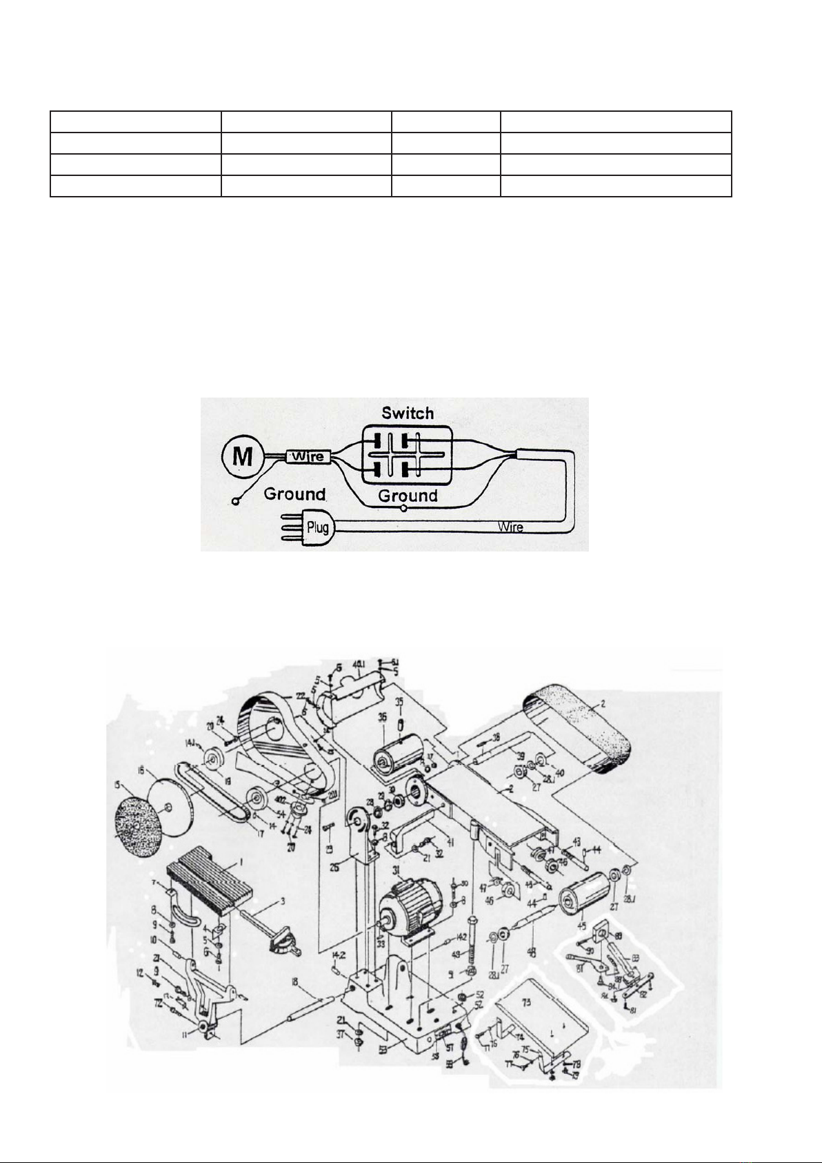
Bordsstorlek 6 1/4" x 12" Skivstorlek 9" dia
Bordslutning 0º - 45º Motor 1/2 hp ~1 hp
Bältstorlek 6" x 48" Mått 696mm x 444mm x 370mm
Bältlutning 0º - 90º Nettovikt 51 kg
Tekniska data
Kopplingsschema
This manual suits for next models
1
Table of contents
Languages:
Other pela tools Sander manuals


