PELLA®INSYNCTIVE®INTEGRATED ENTRY DOOR SENSOR PRODUCT GUIDE | 9
INTEGRATED SENSOR SETUP for Entry Door by Pella with
Multipoint Lock
See Insynctive.Pella.com/Support for how-to videos.
1. Get Started
Plug BRIDGE into an electrical outlet (light will turn green and then
flash blue).
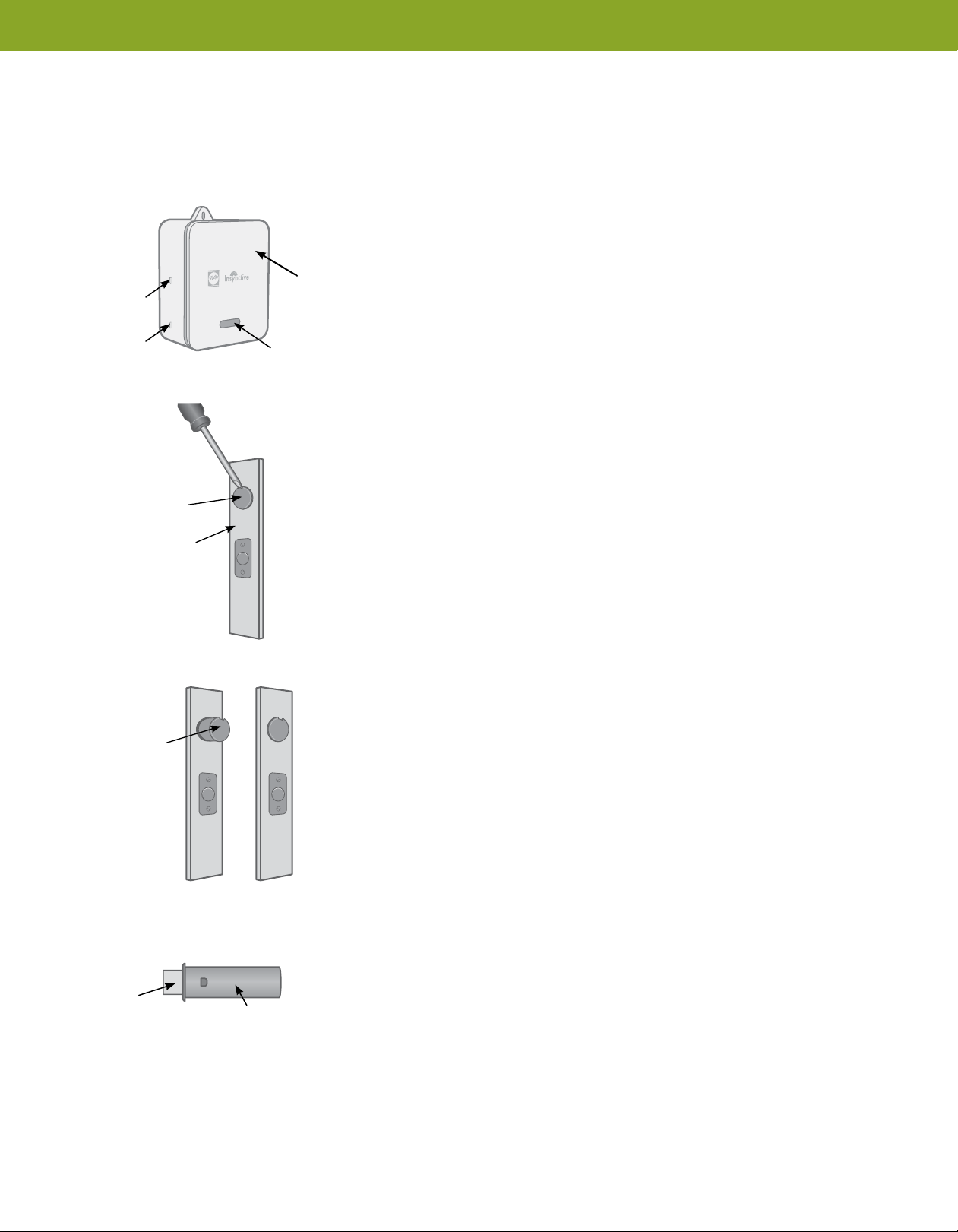
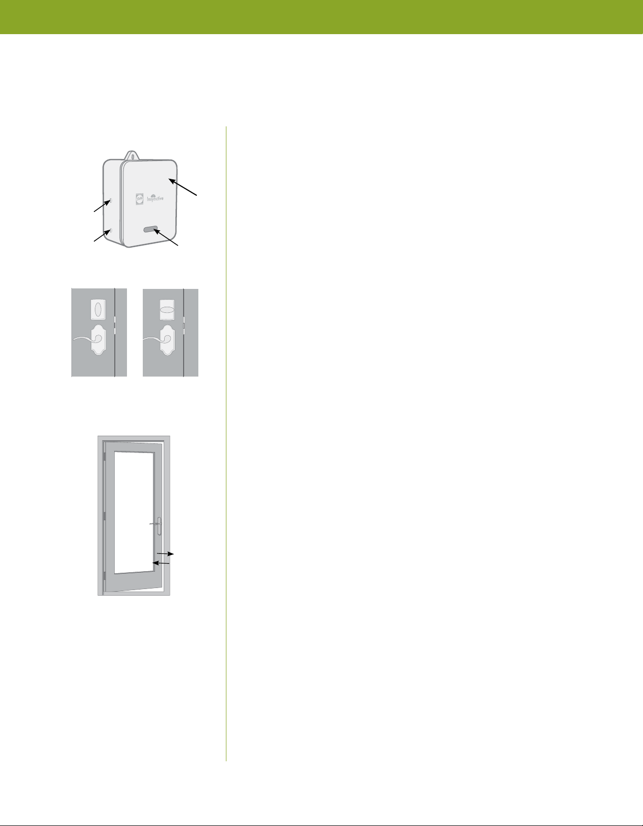
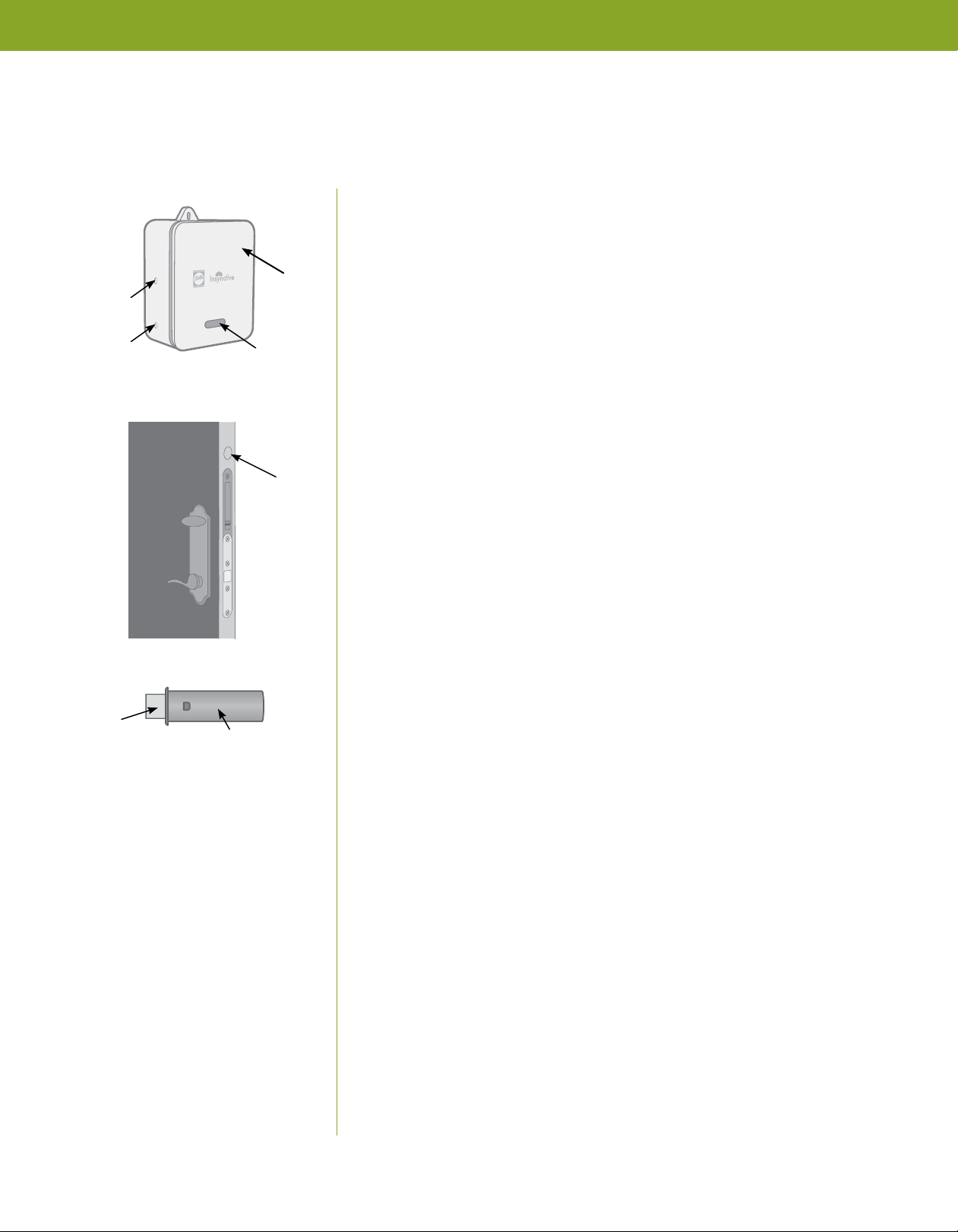
2. Prepare OPEN/CLOSE SENSOR
Use a small flathead screwdriver to remove the plastic endcap from
OPEN/CLOSE SENSOR. Grip the edges of the circuit board and pull
it out to gain access to the battery. Remove the plastic tab from the
battery, then reinsert OPEN/CLOSE SENSOR into your entry door.
Install the plastic endcap back onto OPEN/CLOSE SENSOR.
NOTE: Once the plastic tab is removed from the battery, you will
have 2 minutes to sync your OPEN/CLOSE SENSOR to BRIDGE. If 2
minutes pass without successfully syncing, follow steps on page 13
to remove and reinsert the battery.
You are ready to sync OPEN/CLOSE SENSOR to BRIDGE.
3. Sync OPEN/CLOSE SENSOR to BRIDGE
Each INTEGRATED ENTRY DOOR SENSOR will need to be synced
to BRIDGE.
WITHOUT HOME AUTOMATION (Stand-Alone Mode)
Press and hold BRIDGE Sync button until light begins flashing
orange. The Sync button is the bottom button located on the side
of BRIDGE.
NOTE: BRIDGE is in sync mode while the orange light is flashing.
BRIDGE will remain in sync mode for 2 minutes. BRIDGE will then
beep, and orange light will turn off to indicate BRIDGE exited
sync mode.
To sync OPEN/CLOSE SENSOR to BRIDGE, open then close your
entry door twice within 5 seconds.
Wait for the light on BRIDGE to flash green and beep for 2 seconds.
This will indicate a successful sync.
If OPEN/CLOSE SENSOR sync is unsuccessful, return to Step 2 and
retry the process.
DETAILED INSTRUCTIONS (continued)
LIGHT
SYNC
BUTTON
TEST
BUTTON
BRIDGE
OPEN/CLOSE
SENSOR
PLASTIC
TAB
OPEN/CLOSE
SENSOR