Rev. D 27-06-11 P/N 474131
3
Contents
Section 1. Heater Identification Information (HIN) ............................................................. 4
Heater Data Rating Plate ..................................................................................... 4
Section 2. Introduction .......................................................................................................... 5
Important Notices ................................................................................................................................................................................. 5
Warranty Information ............................................................................................................................................................................ 5
Code Requirements .............................................................................................................................................................................. 6
Consumer Information and Safety Information ...................................................................................................................................... 6 - 8
General Specifications ......................................................................................................................................................................... 8
Section 3. Installation ............................................................................................................. 9
Heater Description ................................................................................................................................................................................ 9
Sequence of Operation ......................................................................................................................................................................... 9
Putting the Heater into Service ............................................................................................................................................................ 9
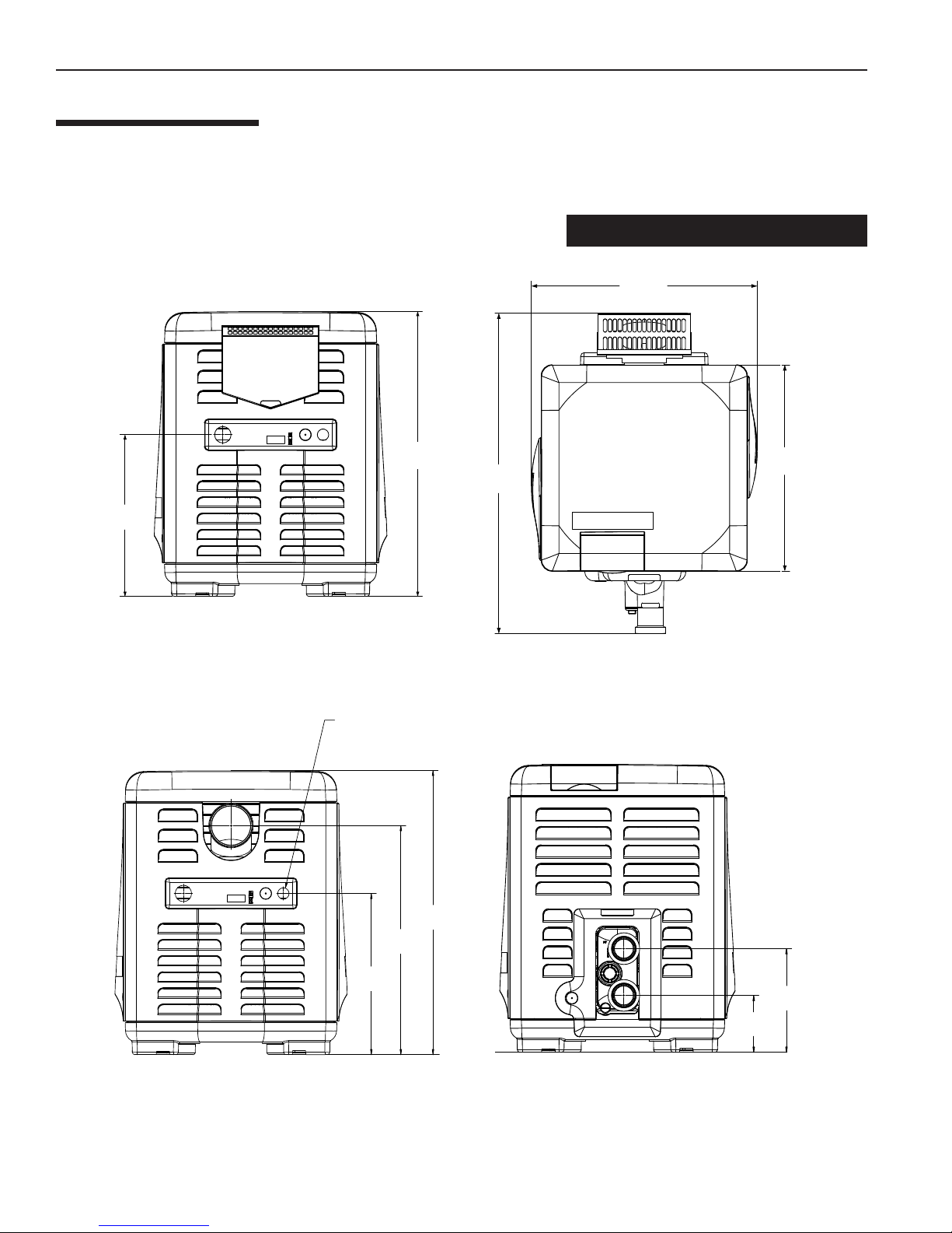
Specifications ...................................................................................................................................................................................... 10
Plumbing Connections .......................................................................................................................................................................... 11
Valves .................................................................................................................................................................................................. 11
Manual By-Pass .................................................................................................................................................................................. 11
Water Connections ............................................................................................................................................................................... 12
Below Pool Installation ......................................................................................................................................................................... 12
Gas Connections ................................................................................................................................................................................. 13
Gas Pipe Sizing ................................................................................................................................................................................... 13
Sediment Trap/Drip Leg ....................................................................................................................................................................... 13
Testing Gas Leaks and Gas Pressure .................................................................................................................................................. 14
Gas Pressure Requirements ................................................................................................................................................................ 14
Outdoor Installation / Heater Clearances .............................................................................................................................................. 15 - 16
Indoor Venting—General Requirements Heater Clearances / Outside Vent Removal ) .......................................................................... 17
Combustion Air Supply / Corrosive Vapors and Possible Causes ..................................................................................................... 18
Vent Installation (Indoor Installation or Outdoor Shelter) - Vertical Venting ........................................................................................ 18-21
Horizontal or Vertical Venting - Using Single-Wall Stainless Gas Vent ............................................................................................. 21
Connecting Single-Wall Stainless Steel Vent to the Heater .............................................................................................................. 22
Horizontal or Vertical Venting Flexible Duct (Flex-Vent) .................................................................................................................... 24
Corrosive Vapors and Possible Causes ................................................................................................................................................ 25
Control Panel Indexing ......................................................................................................................................................................... 25
Final Installation Check ........................................................................................................................................................................ 25
Electrical Connections .......................................................................................................................................................................... 26
Fireman’s Switch Connection/Remote Control Connections .................................................................................................................. 27
MasterTemp Wiring Diagram / Electrical Schematic Ladder Diagram .................................................................................................... 28 - 29
Section 4. Operation .............................................................................................................................................. 30
Basic System Operation / HSI (Hot-Surface Ignition) Lighting/Operation .............................................................................................. 30
Operating Instructions .......................................................................................................................................................................... 31
To Turn Off Gas to Appliance ............................................................................................................................................................... 31
Safety Controls (Air Flow Switch / Water Pressure Switch / Hight Limits / Operation of Ignitiion Module) ............................................ 32 - 33
Operating the Control Panel / Temperature Setting / Maximum Temperature Set Point ......................................................................... 33
Section 5. Troubleshooting ................................................................................................... 35
Initial Troubleshooting and Troubleshooting Chart ................................................................................................................................. 35
Heater Will Not Fire Troubleshooting (A, B, C, D) ................................................................................................................................ 36 - 39
LED Diagnostics (AGS, AFS, HLS, PS Thermistor) ............................................................................................................................ 40 - 41
Burner / Heat Exchanger Troubleshooting ............................................................................................................................................ 42
Section 6. Maintenance ..........................................................................................................43
Care and Maintenance .......................................................................................................................................................................... 43
Pressure Relief Valve ........................................................................................................................................................................... 43
After Start-Up ...................................................................................................................................................................................... 44
Spring, Fall (Autumn) and Winter Operation ........................................................................................................................................ 44
Maintaining Pool Temperature / Energy Saving Tips ............................................................................................................................. 45
Chemical Balance ................................................................................................................................................................................ 45 - 46
Replacement Parts .............................................................................................................................................................................. 47 - 51