Pentair FAIRBANKS NUJHUIS FBM20 Troubleshooting guide

FBM(X)20
BASIN MIXER CONTROL PANEL
INSTRUCTION AND SERVICE MANUAL
NOTE! To the installer: Please make sure you provide this manual to the owner of the equipment or to the responsible
party who maintains the system.
Part #FM-03-544 | © 2016 Pentair plc | 05/25/16

FBM(X)20 Basin Mixer Control Panel
Instruction and Service Manual
2
INTRODUCTION:
GENERAL:
Thank you for purchasing your Fairbanks Nijhuis®Basin Mixer Control Panel. To help ensure years of trouble-free operation,
please read the following manual carefully.
BEFORE OPERATION. Read the following instructions carefully. Reasonable care and safe methods should be practiced. Check
local codes and requirements before installation.
CALIFORNIA PROPOSITION 65 WARNING:
This product and related accessories contain chemicals known to the State of California to cause cancer, birth defects or
other reproductive harm.
ATTENTION: This manual contains important information for the safe use of this product. Read this manual completely
before using this product and refer to it often for continued safe product use. DO NOT THROW AWAY OR LOSE THIS
MANUAL. Keep it in a safe place so that you may refer to it often.
UNPACKING PANEL. Remove panel from carton. When unpacking unit, check for concealed damage. Claims for damage must be
made at the receiving end through the delivery carrier. Damage cannot be processed from the factory.
POWER SUPPLY:
WARNING:
Do not attempt to wire this control box unless you have a good working knowledge of electricity and are familiar with the
state and local codes. If you are in doubt about anything, contact a qualified electrician.
Do not attempt to operate this unit on any other voltage or power distribution other than for which it was originally
designed (check nameplate). Failure to comply with this will result in the immediate cancellation of all warranties
and claims.
It is advisable to put the panel on its own circuit using a circuit breaker adequately sized to protect the mixer. Check state and local
codes for the correct wire size and circuit protection to use. The wire should be sized large enough to handle the full load current of
the mixer you are operating and any voltage drop that might occur due to long service runs.
Run power supply lines to the control box and secure (knockouts are not supplied in this box). Select a convenient location on the
bottom to enter the box with the power supply. Cut a hole with a chassis punch. Caution should be taken not to get metal chips in
the components while cutting hole. After the hole is cut, any metal particles must be removed from the box. Failure to do so may
result in premature component failure.
Connect incoming power to the terminal blocks per the included schematic and all necessary ground wires to the ground lug at the
bottom right of the box. The ground lug should be fastened to a good driven earth ground by one of the methods described in the
National Electric Code. NEC does not permit using ground as a current-carrying conductor, therefore a neutral must be provided for
115 volt 1 phase, 208 volt 1 phase, 230 volt 1 phase, or 208 volt 3 phase systems.
WARNING:
Before handling these mixers and controls, always disconnect the power first. Do not smoke or use sparkable electrical
devices or flames in a septic (gaseous) or possible septic sump.
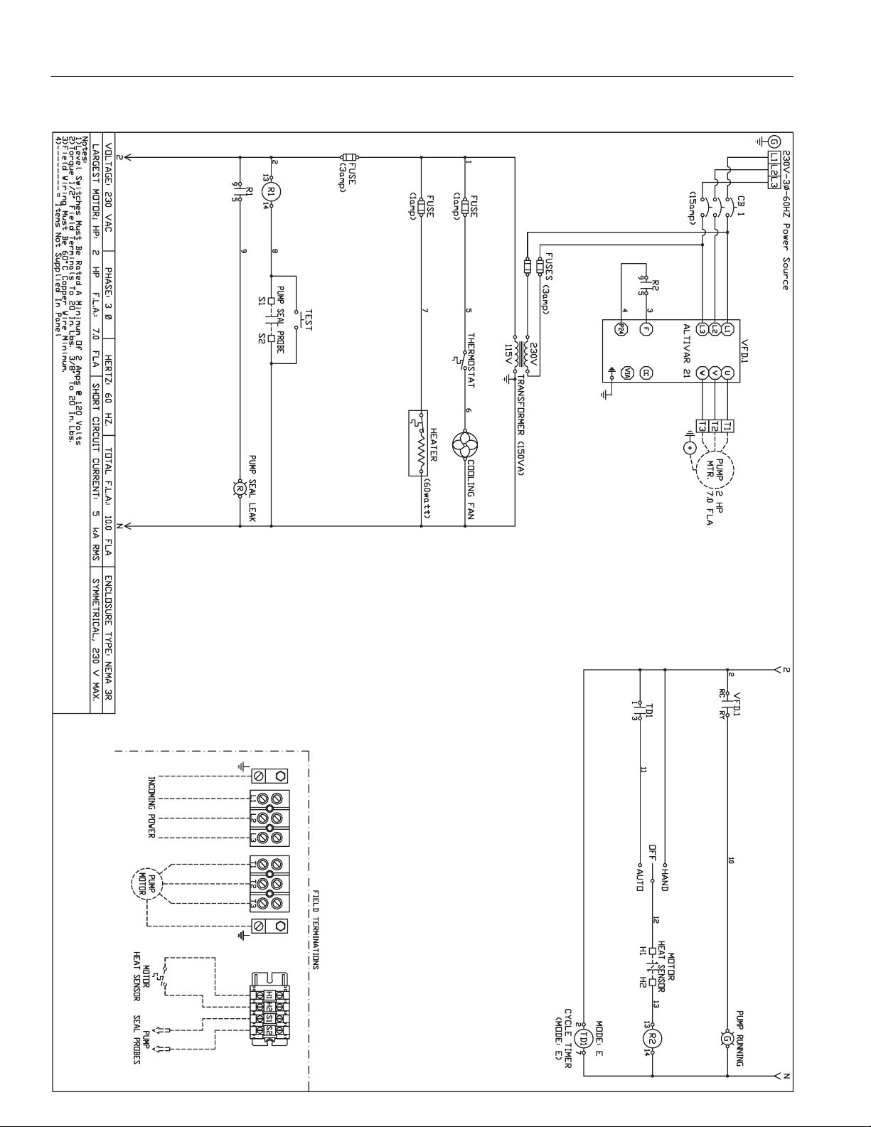
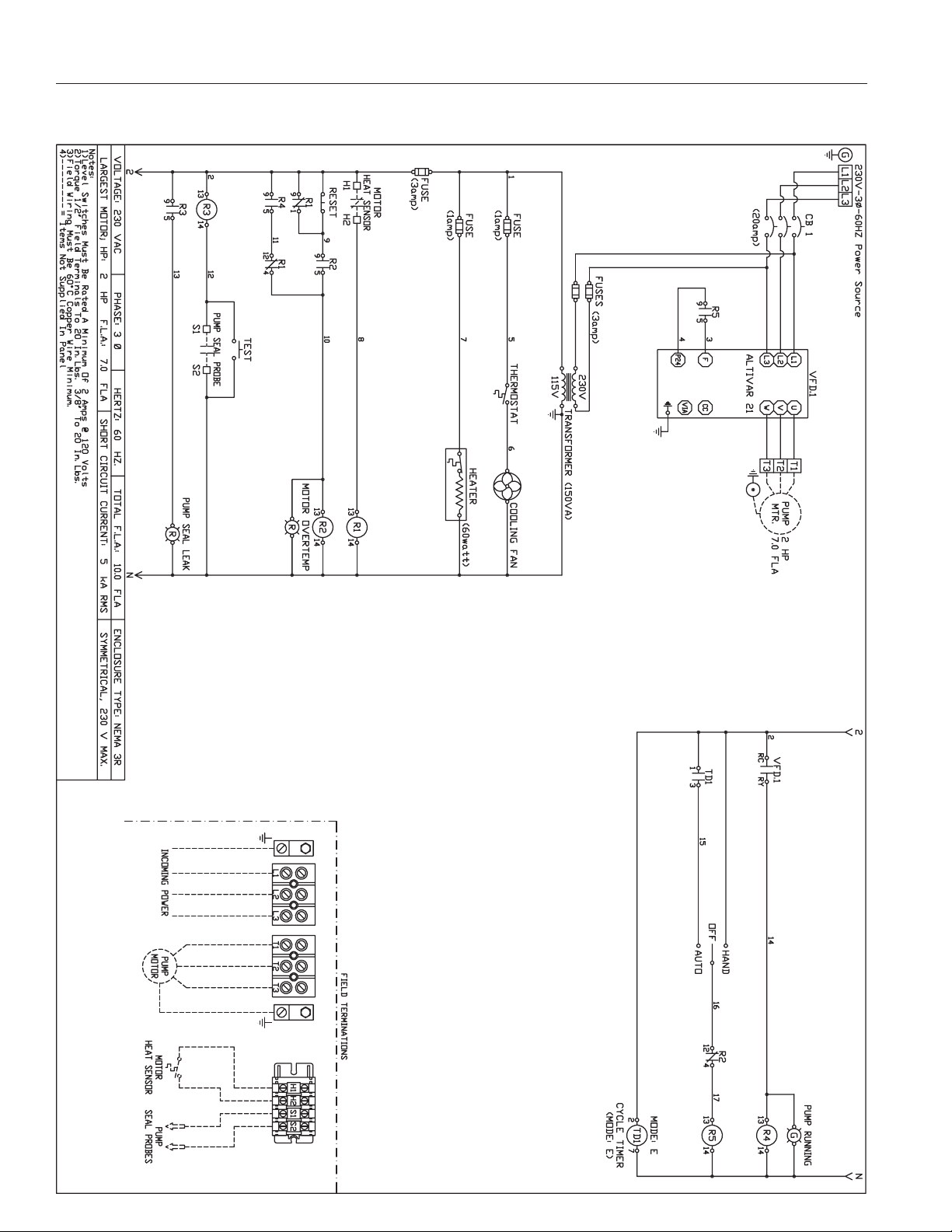
ELECTRICAL CONNECTIONS: The contractor must conform to the latest requirements of the National Electrical Code. All conduit
and cables shall be in accordance with NEC Code NFPA #70. To maintain UL and CSA ENCL rating, use the same type UL and
CSA weatherproof conduit hubs when connecting to this enclosure. Prior to conducting any installation, repair or service with
regard to the control panel, refer to the schematic appropriate for that panel. The schematic will provide guidance with regard to the
terminal block connections.
CAUTION:
A nonmetallic enclosure does not provide grounding conduit connections. Use grounding bushing and jumper wires.
MAKE THE FOLLOWING ELECTRICAL CONNECTIONS:
a. Connect the mixer leads to the control panel.
b. Connect the mixer heat sensor and seal failure leads (if available on the mixer) to the appropriate terminal blocks in the
control panel.
c. Before connecting power to the control panel, make sure all control switches (e.g. H-O-A switch) and protective devices (e.g.
breakers) are in the Off position. Now connect power to the terminal block or the circuit breaker as directed by the schematic.
d. Control panel must be grounded properly per NEC and/or local codes. To facilitate this, a ground lug is provided on the
control panel.

FBM(X)20 Basin Mixer Control Panel
Instruction and Service Manual
3
Terminal Mixer Wire Color Function
M1 White Mixer Power
M2 Black Mixer Power
M3 Red Mixer Power
G Green Ground
1 Orange Seal Leak Sensor
2 Blue Heat Sensor
3 White w/Black Stripe Sensor Common Wire
T1 White Mixer Power
T2 Black Mixer Power
T3 Red Mixer Power
G Green Ground
S1 Red Seal Leak Sensor
S2 Orange Seal Leak Sensor
H1 Black Heat Sensor
H2 (MBM) White Heat Sensor
H2 (MBMX) White/Blue Tracer Heat Sensor
START-UP OPERATION:
1. Check junction box for moisture. Moisture may cause chattering of relays/contactors.
2. WARNING: Live voltage can kill! Check incoming power voltage to make sure that it is correct for panel and
mixer model.
3. Energize control panel. (Turn on power to panel.)
4. WARNING: Live voltage can kill! Check voltage to the panel and at secondary of control transformer using a
voltmeter. If no transformer is supplied, check voltage at the circuit breakers.
5. Set the application specific parameters for the VFD.
a. With power to the VFD and the H-O-A switch in the Off position, power on, hit the Menu button until the pointer is above
main menu.
b. Use up and down key to switch parameter groups. Hit OK to set a parameter group.
c. Use up and down key to switch parameters. Hit OK to set a parameter group. Use up and down key to change
parameters. After each change, hit OK again to set the value.
d. Use the back button to get back to the parameter groups.
e. Parameters to be set at installation:
i. Set 1-24 motor current; see chart below.
ii. Set 1-25 motor nominal speed; 1150 or 1750; see chart below.
iii. Set 1-29 AMT; set to 2 and follow instructions then set back to 0.
iv. Set 3-02 speed in Hz; 30–60 Hz.
f. Hit Auto On button and move H-O-A switch to Auto position. When timer contact is closed motor should run.
Mixer Model Amps Speed Voltage
FBM(X)20M4-03 8 A 1750 RPM 200V
FBM(X)20M4-23 7 A 1750 RPM 230V
FBM(X)20M4-43 3.5 A 1750 RPM 460V
FBM(X)20M6-03 5.5 A 1150 RPM 200V
FBM(X)20M6-23 4.8 A 1150 RPM 230V
FBM(X)20M6-43 2.4 A 1150 RPM 460V
Speed charts – FOR REFERENCE ONLY.
M1
M2
M3
L1
L2
L3
1
2
3
Mixer Motor
Power Terminals
Incoming Power
Terminals
Mixer Seal Leak and
Heat Sensor Terminals
Ground

FBM(X)20 Basin Mixer Control Panel
Instruction and Service Manual
4
WARNING:
Do not exceed 60 Hz or go below 30 Hz. Exceeding 60 Hz will draw more horsepower from the motor than it was designed
for. Running at lower than 30 Hz may not supply enough starting torque to the mixer unit.
6. With H-O-A switch in Hand, check mixer to verify the mixer is running. On three phase power, check to see if each mixer has
proper rotation.
7. Check full load current with amp probe and compare it with the nameplate rating. On three phase mixers, check all three
phases. Use a true RMS meter to obtain accurate readings.
8. Set range and adjustment settings on timer.
a. Select one of the 16 built-in time ranges by setting the rotary switch per a chart on the unit and adjust within that range
using the knob on top.
9. With H-O-A switch in Auto, check timer operation. For sequence of operation, refer to design specification.
10. Make sure H-O-A switch is left in the Auto position after start-up is completed.
MIXER START-UP: Refer to mixer Installation and Service Manual.
MIXER MAINTENANCE:
WARNING:
Before handling these mixers and controls, always disconnect the
power first. Do not smoke or use sparkable electrical devices or
flames in a septic (gaseous) or possible septic sump.
The maintenance schedule will vary with operating and environmental con-
ditions. It will also vary with the specific type of control supplied. The list
herein is a guide only.
1. Exercise breaker through one cycle. Be careful not to over-exercise
as the breaker is not a switching device. Excessive operations tend to
affect the trip curve of the breaker.
2. Check relay for excessive humming. This can be accomplished by
turning mixer on and off in the Hand mode with the H-O-A switch.
3. Check mixer run light by running mixer in Hand mode. Check bulb(s)
in any other light(s).
4. With the power off, check continuity of all control fuses.
5. Check voltage at primary and secondary of control transformer.
B
a
c
k
1. Numeric display
2. Menu key
3. Navigation keys
4. Operation keys and LEDS
Off
Reset
Hand
On
Auto
On
OK
Menu
Status Quick
Menu
Main
Menu
On
Warn.
Alarm
1.
2.
3.
4.
The LCP is divided into four functional groups:
Programming with LCP12 keypad

FBM(X)20 Basin Mixer Control Panel
Instruction and Service Manual
5
TIMER CONTROLS:
Your control panel is equipped with a repeat cycle time delay relay (On
Time first followed by Off Time and repeating). The On and Off Times have
rotary switch selectable timing ranges and adjustment knobs for selecting
the time within that range. Select one of the 16 built-in ranges by setting
the rotary switch per a chart on the time delay relay and adjust within that
range using the appropriate knob.
SEAL FAILURE:
Your mixer is equipped with a seal fail (moisture) sensor. The presence of water energizes the seal leak warning
output. This activates a warning light or alarm only, and does not stop the motor. It indicates a leak has occurred and
the mixer must be repaired.
The resistance across the moisture seal (seal failure) probes should be checked after a seal leak warning light has
lit. This can be done by disconnecting the control wires from the control panel and measuring the resistance with
an ohmmeter between the wires. Refer to the control panel schematic for wire identification. For a standard, non-
hazardous location mixer the reading should be 100,000 ohms or greater, and for a hazardous location mixer the
reading should be above 33,000 ohms. If the measured values are below those indicated above, then the mixer may
have a lower seal failure and require service.
On control panels for hazardous location applications the seal leak test switch tests the seal leak circuitry continuity.
When pushed, the seal leak test bulb should light. If the test bulb does not light, it means either the wiring circuitry to
the seal leak probes has been broken or the bulb has burned out.
6. Check the mixer full load amps.
7. Check junction boxes for moisture. Moisture may cause chattering of relays and contactors.
8. Check for moisture inside control panel enclosure. Moisture can cause damage to electrical components. Check door gasket
for proper seal.
9. Check labels to verify they have not been damaged.
10. Lubricate enclosure hinges.
SPARE PARTS LIST: The following is a list of recommended spare parts. However, conditions of service vary significantly and
a general list may not in its entirety be applicable to a given installation. The user should exercise judgment in defining specific
requirements based on this guide.
1. Fuses for control transformer primary and secondary. (If required.)
2. VFD.
3. Bulbs for any light requiring a bulb.
4. Control transformer. (If required.)
5. Control and time delay relay. (If required.)
ON TIME
OFF TIME
MIN MAX
MIN MAX
A
I
PB
JH
OC
KG
ND
ME
LF
I
A
HJ
BP
GK
CO
FL
EM
DN
“On Time”
range selection
Exam
ple dial positions
shown:
On Time ~ 10 sec
Off Time ~ 18 sec
“Off Time”
range selection
“On T
ime” adjustment
within range selected
“Off Time” adjustment
within range selected
Dial Setting Timing Range
A 0.6 – 2.5 Sec.
B 1.5 – 5 Sec.
C 2.5 – 10.5 Sec.
D 5 – 21 Sec.
E 10 – 42 Sec.
F 0.4 – 1.4 Min.
G 0.7 – 2.8 Min.
H 1.5 – 5.5 Min.
I 3 – 11 Min.
J 5.5 – 22.5 Min.
K 11 – 45 Min.
L 0.4 – 1.5 Hr.
M 0.8 – 3 Hr.
N 1.5 – 6 Hr.
O 3 – 12 Hr.
P 6 – 24 Hr.

FBM(X)20 Basin Mixer Control Panel
Instruction and Service Manual
6
TEMPERATURE FAILURES:
NOTE:
Fairbanks Nijhuis control panels supply the correct circuitry for moisture and heat sensor connections.
Your mixer is equipped with temperature fail sensor thermostats attached directly to the motor windings. The
thermostats open if the motor windings see excessive heat and, in turn, open the motor contactor in the control panel,
breaking the power to the mixer.
When the motor is stopped due to an overheated condition, it will not start until the motor has cooled and the heat
sensor reset button is manually pushed on the front of the control panel.
NOTE:
Failure to use proper circuitry and to connect the motor overheat protection in the control panel would negate
all warranties and Factory Mutual Approval.
WARNING:
Before handling the mixer and controls, always disconnect the power first. Do not smoke or use sparkable
electrical devices or flames in a septic (gaseous) or possible septic sump.
TROUBLESHOOTING:
1. Mixer does not run in Hand position.
a. Check mixer circuit breaker and control fuse for tripping or blown condition.
b. Check incoming power voltage and control circuit voltage.
c. Check VFD to see if it is tripped. Reset VFD if tripped and check mixer current with ammeter.
d. With the power off, check motor heat sensor continuity.
e. Check wiring of mixer to control panel. It should agree with the schematic.
2. Mixer does not run in Auto position.
a. Check items (a.) through (e.) per Item #1 above.
b. Check knob settings on timer to ensure proper sequencing. Check both On and Off Time range selector
knobs as well as On and Off Time adjustment knobs.
c. If mixer does not run in Auto mode, check Auto circuit wiring in panel.
3. Mixer runs, but run light does not energize.
a. Remove light and check with an ohmmeter.
b. Check run light wiring.
4. Severe humming/chattering of control relay.
a. There may be low voltage. Check voltage at primary and secondary of control transformer using a voltmeter.
This low voltage condition may cause severe chattering and burnout of relay.
b. Relay may have dust around magnet of coil structure. Dry or clean as required.
c. Check voltage to the control panel. Relays require a minimum of 80% of full voltage to pull in without chatter.
If the problem is a recurring one, measure voltage with recorder on a 24 hour basis.
d. Dry out the junction box (if furnished); moisture in the junction box may cause relays to energize intermittently.
5. Short cycling mixer.
a. Check timer controls.
6. Run light stays on.
a. Selector switch may be in the Hand position.
7. Nuisance tripping of overload on VFD or circuit breakers.
a. Check mixer amp draw with amp probe and compare to nameplate amps on mixer.
b. The propeller may be locked up due to excessive debris or solids.
c. Possible motor failure (fault in windings).
d. Mixer may be miswired to terminal block.
e. Voltage and current unbalance. Voltage unbalance on three phase power sources can cause motor current
to become unbalanced and excessive heating will result. Tripping of the overload protection and premature
motor failures can be expected if the current unbalance exceeds five percent.

FBM(X)20 Basin Mixer Control Panel
Instruction and Service Manual
7
Percent Maximum Current
Current = Difference from x 100
Unbalance Average Current
Average Current
To determine if motor current unbalance is a function of the motor or the power supply:
1. Label the leads and the terminals 1, 2, and 3 respectively.
2. Record the amperage for each lead.
3. Move each lead to the next terminal (1 to 2, 2 to 3, 3 to 1).
4. Again read the amperage of each lead.
5. Move each lead to the next terminal (1 to 3, 2 to 1, 3 to 2).
6. Again read the amperage of each lead.
7. If the unbalance moves with the motor leads, the unbalance is caused by the motor. If the unbalance remains
with the terminals, the unbalance is in the power supply.
8. If the current unbalance exceeds five percent, nuisance tripping or excessive heating will result.
9. Connect leads for the lowest percent of current unbalance.
FACTORY SET PARAMETERS FOR VFD:
Parameters set at factory for 230V panels
1) Set 1-20 motor power 1.5 kW or 2 HP
2) Set 1-22 motor voltage 230 volts
3) Set 1-24 motor current 4.8 amps
4) Set 1-25 motor nominal speed 1150
5) Set 3-02 min. speed in Hz 30
6) Set 3-03 max. speed in Hz 60
7) Set 3-15 0
8) Set 3-16 0
9) Set 3-41 ramp up time 3.00 sec.
10) Set 3-42 ramp down time 3.00 sec.
Parameters set at factory for 460V panels
1) Set 1-20 motor power 1.5 kW or 2 HP
2) Set 1-22 motor voltage 460 volts
3) Set 1-24 motor current 2.4 amps
4) Set 1-25 motor nominal speed 1150
5) Set 3-02 min. speed in Hz 30
6) Set 3-03 max. speed in Hz 60
7) Set 3-15 0
8) Set 3-16 0
9) Set 3-41 ramp up time 3.00 sec.
10) Set 3-42 ramp down time 3.00 sec.

FBM(X)20 Basin Mixer Control Panel
Instruction and Service Manual
8
STANDARD LOCATION 230V, 3 PHASE, 60 HZ WIRING SCHEMATIC

FBM(X)20 Basin Mixer Control Panel
Instruction and Service Manual
9
STANDARD LOCATION 460V, 3 PHASE, 60 HZ WIRING SCHEMATIC

FBM(X)20 Basin Mixer Control Panel
Instruction and Service Manual
10
HAZARDOUS LOCATION 230V, 3 PHASE, 60 HZ WIRING SCHEMATIC

FBM(X)20 Basin Mixer Control Panel
Instruction and Service Manual
11
HAZARDOUS LOCATION 460V, 3 PHASE, 60 HZ WIRING SCHEMATIC

USA THE NETHERLANDS
3601 FAIRBANKS AVENUE PARALLELWEG 4
KANSAS CITY, KANSAS 66106 7102 DE WINTERSWIJK
630-859-7000, FAX 630-859-7060 T +31 101543 547474
www.FairbanksNijhuis.com
Warranty Rev. 12/13
Pentair Fairbanks Nijhuis® warrants its products against defects in material and workmanship for a period of 12months
from the date of shipment from Pentair Fairbanks Nijhuis or 18 months from the manufacturing date, whichever
occurs first – provided that such products are used in compliance with the requirements of the Pentair Fairbanks
Nijhuis catalog and technical manuals for use in pumping raw sewage, municipal wastewater or similar, abrasive-free,
noncorrosiveliquids.
During the warranty period and subject to the conditions set forth, Pentair Fairbanks Nijhuis, at its discretion, will repair
or replace to the original user, the parts that prove defective in materials and workmanship. Pentair Fairbanks Nijhuis
reserves the right to change or improve its products or any portions thereof without being obligated to provide such a
change or improvement for prior sold and/or shipped units.
Start-up reports and electrical schematics may be required to support warranty claims. Submit at the time of start-up
through the Pentair Fairbanks Nijhuis website: http://forms.pentairliterature.com/startupform/startupform.asp?type=m.
Warranty is effective only if Pentair Fairbanks Nijhuis authorized control panels are used. All seal fail and heat sensing
devices must be hooked up, functional and monitored or this warranty will be void. Pentair Fairbanks Nijhuis will cover
only the lower seal and labor thereof for all dual seal pumps. Under no circumstance will Pentair Fairbanks Nijhuis be
responsible for the cost of field labor, travel expenses, rented equipment, removal/reinstallation costs or freight expenses
to and from the factory or an authorized Pentair Fairbanks Nijhuis service facility.
This limited warranty will not apply: (a) to defects or malfunctions resulting from failure to properly install, operate or
maintain the unit in accordance with the printed instructions provided; (b) to failures resulting from abuse, accident or
negligence; (c) to normal maintenance services and parts used in connection with such service; (d) to units that are not
installed in accordance with applicable local codes, ordinances and good trade practices; (e) if the unit is moved from
its original installation location; (f) if unit is used for purposes other than for what it is designed and manufactured; (g)
to any unit that has been repaired or altered by anyone other than Pentair Fairbanks Nijhuis or an authorized Pentair
Fairbanks Nijhuis service provider; (h) to any unit that has been repaired using non factory specified/OEM parts.
Warranty Exclusions: PENTAIR FAIRBANKS NIJHUIS MAKES NO EXPRESS OR IMPLIED WARRANTIES THAT EXTEND
BEYOND THE DESCRIPTION ON THE FACE HEREOF. PENTAIR FAIRBANKS NIJHUIS SPECIFICALLY DISCLAIMS THE
IMPLIED WARRANTIES OF MERCHANTABILITY AND FITNESS FOR ANY PARTICULAR PURPOSE.
Liability Limitation: IN NO EVENT SHALL PENTAIR FAIRBANKS NIJHUIS BE LIABLE OR RESPONSIBLE FOR
CONSEQUENTIAL, INCIDENTAL OR SPECIAL DAMAGES RESULTING FROM OR RELATED IN ANY MANNER TO ANY
PENTAIR FAIRBANKS NIJHUIS PRODUCT OR PARTS THEREOF. PERSONAL INJURY AND/OR PROPERTY DAMAGE MAY
RESULT FROM IMPROPER INSTALLATION. PENTAIR FAIRBANKS NIJHUIS DISCLAIMS ALL LIABILITY, INCLUDING
LIABILITY UNDER THIS WARRANTY, FOR IMPROPER INSTALLATION. PENTAIR FAIRBANKS NIJHUIS RECOMMENDS
INSTALLATION BY PROFESSIONALS.
Some states do not permit some or all of the above warranty limitations or the exclusion or limitation of incidental or
consequential damages and therefore such limitations may not apply to you. No warranties or representations at any
time made by any representatives of Pentair Fairbanks Nijhuis shall vary or expand the provision hereof.
STANDARD LIMITED WARRANTY
This manual suits for next models
1
Table of contents
Other Pentair Control Panel manuals

Pentair
Pentair Hydromatic SPC-PANEL Manual

Pentair
Pentair Hydromatic H-03-000 Manual

Pentair
Pentair Hydromatic Manual

Pentair
Pentair Myers CGL-01SW Manual

Pentair
Pentair MYERS CNC-600-43DW Manual

Pentair
Pentair ICHNDHLD User manual

Pentair
Pentair Hydromatic NOVUS 3000 Series Manual

Pentair
Pentair INTELLICENTER User manual
Popular Control Panel manuals by other brands

Trikdis
Trikdis FLEXi SP3 user manual

AUTOTERM
AUTOTERM PU-27 operating manual

JCM Technologies
JCM Technologies F30 user manual

Arrowhead Alarm Products
Arrowhead Alarm Products ELITE SX-2 Installation & programming guide

Honeywell
Honeywell Notifier ST.PL4+ Installation and user manual

Dynisco
Dynisco 1400 instructions