Pentair LINCOLN 416 User manual

LINCOLN
APENTAIR COMPANY
Model Nos. 416, 83776, 83777
FLUID DISPENSER
Series "F"
3:1 RATIO, OUTPUT -6CU. iN./CYL.
MIN. AIR PRESSURE -30 PSI
MAX. AIR PRESSURE -200 PSI
MAX. OUTPUT PRESSURE -600 PSI
OWNERS MANUAL
IT IS THE RESPONSIBILITY OF THE OWNER AND/OR OPERATOR TO PROPERLY USE AND MAINTAIN THIS EQUIPMENT.
CAREFULLY READ AND UNDERSTAND THE INSTRUCTIONS AND WARNINGS IN THIS MANUAL BEFORE OPERATING THIS
EQUIPMENT.
If the operator is not fluent in English, the instructions and warnings shall be read and discussed in the operators native language,
making sure the operator comprehends the contents.
This equipment complies with OSHA Standards where applicable.
WARNING
DO NOT exceed the stated maximum working pressure of the pump
or of the lowest rated component in your system.
DO NOT alter or modify any part of this equipment.
DO NOT operate this equipment with combustible gas.
DO NOT attempt to repair or disassemble the equipment while the
system is pressurized.
TIGHTEN all fluid connections securely before using this equipment.
ALWAYS read and follow the fluid manufacture's recommendations
regarding fluid compatibility, and the use of protective clothing and
equipment.
CHECK all equipment regularly and repair or replace worn or dam-
aged parts immediately.
IMPORTANT: Failure to heed these warnings including misuse,
overpressurizing, modifying parts, using incompatible chemicals and
fluids, or using worn or damaged parts, may result in equipment
damage and/or serious personal injury, fire, explosion, or property
damage.
CONTENTS
Safety instructions ....................................................
Inspection Instructions ................................................
Damaged Pumps ......................................................
Installation ............................................................
Operation .............................................................
Maintenance ..........................................................
General Dimensions ...................................................
Disassembly Procedure ...............................................
Parts Breakdown ......................................................
Service Parts ..........................................................
Troubleshooting Chart ................................................
Accessories ...........................................................
Warranty ..............................................................
PAGE
2
2
2
2
3
3
3
4
4-6
7
7
7
8
This manual contains IMPORTANT WARNINGS and INSTRUCTIONS READ AND RETAIN FOR REFERENCE
LINCOLN One Lincoln Way Section -A36
St. Louis, Missouri 63120-1578 Copyright 1988
APENTAIR COMPANY (314) 679-4200 Printed in U.S.A
Customer Service (314) 679-4300 Page -1H
Rev. AForm 406009

SAFETY INSTRUCTIONS
For professional use only. Osbserve
allwarnings. Read and unserstand all
instructions before operating equip-
ment. Extreme caution should beused
when operating this equipment asper-
sonol injury and/or property damage
can result from equipment misuse.
Adequate protection isrecommended
toprevent splashing ofmaterial onto
the skin orinto the eyes.
WARNING
WARNING
NEVER point dispensing
valve atany part ofthe body or
atanother person.
PRESSURE RELIEF
PROCEDURE
Toreduce the risk ofserious
bodily injury, including splash-
ing into the eyes or onto the
skin, always follows this proce-
dure When ever you shut off the
pump, when checking or serv-
icing any part of the system,
and when installing, cleaning
or changing any part of the
system.
1. Disconnect air to the pump.
2. Point the dispensing valve
away from yourself and
others.
3. Open the dispensing valve
into an appropriate container
until pressure is relieved.
If you suspect that the dis-
pensing valve or hose is com-
pletely clogged orthat pressure
has not been fully relieved after
following the above procedure,
VERY SLOWLY loosen the hose
end coupling to relieve pressure
gradually, then loosen comple-
tely. Now clear the valve or
hose.
WARNING
WARNING
NEVER trytostop ordeflect
material from dispensing valve
orleakig connection orcom-
ponent with your hand orbody.
WARNING
ALWAYS check equipment
forproper operation before each
use, making sure safety devices
are inplace and operating porp-
erly. DONOT after ormodify
any part ofequipment as
this may cause amalfunction
and result inserious bodily
injury.
INSPECTION
INSTRUCTIONS
WARNING
ALWAYS follow the pressure
relief procedure after shutting
offthe pump, when checking
orservicing any part ofthe sys-
tem; and when installing, clean-
ing orchanging any part ofthe
system.
If overpressurizing of the equipment
is believed to hav occurred, contact the
factory authorized warranty and service
center nearest you for inspection of the
pump.
Specialized equipment and knowl-
edge is required for repair of this pump.
Contact the factory authorized warranty
and service center nearest you for repair
or adjustments other than maintenance
specified in this manual.
Annual inspection by the factory
authorized warranty and service center
nearest you is recommended.
Alist of factory authorized warranty
and service centers is available upon
request.
DAMAGED PUMPS
Any pump that appears to be damaged
in any way, is badly worn or operates
abnormally shall be removed from use
until repairs are made. Contact the
factory authorized warranty and service
center nearest you for repairs.
INSTALLATION
The typical installation shown is only
aguide for selecting and installing sys-
tem components. Contact your Lincoln
Representative for assistance in design-
ing asystem to suit your specific needs.
An air line filter/regulator/lubricator
isrecommended for use with your Lincoln
pump to remove harmful dirt and mois-
ture from the Compressed air supply,
and to provide automatic lubrication to
the air motor.
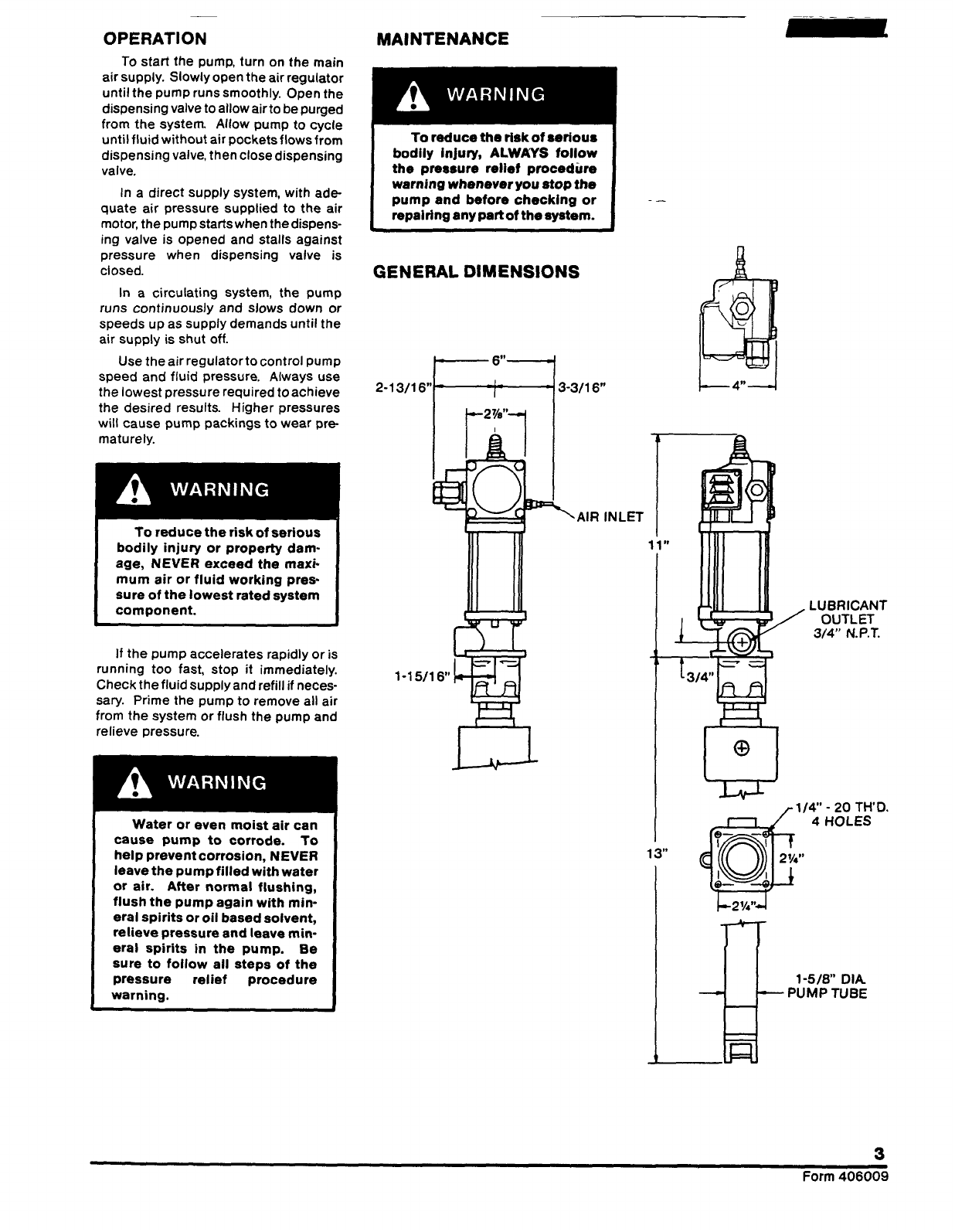
This pump can develop 600
PSl working pressure at 200
PSl maximum incoming air
pressure. Be sure that all sys-
tem equipment and accessories
are rated to withstand the maxi-
mum working pressure of this
pump. DO NOT exceed the
maximum working pressure of
the lowest rated component in
the system.
Flush the supply lines and hoses
with mineral spirits or oil based solvent
and blow dry with air before connecting
them to the system. This is to purge any
contaminants such as dirt, moisture, or
metal shavings that could damage the
pump or system components.
The pump was tested in lightweight
oil which was left in it to protect the
pump from corrosion. Flushing of the
pump before connecting it to the sys-
tem might be desired to prevent Pos-
sible contamination of the fluid you are
pumping.
WARNING
To reduce the risk of injury
from splashing orstatic sparking
when flushing the pump with
mineral spirits or oil based sol-
vent, always hold ametal part
of the dispensing valve firmly
to the side of agrounded metal
pail and operate pump at lowest
possible fluid pressure.
WARNING
ALWAYS read and follow the
fluid and solvent manufacture's
recommedndations regarding the
use ofprotective clothing and
equipment.

OPERATION
To start the pump, turn on the main
airsupply. Slowly open the airregulator
until the pump runs smoothly. Open the
dispensing valve to allow air to be purged
from the system. Allow pump to cycle
until fluid without air pockets flows from
dispensing valve, then close dispensing
valve.
In adirect supply system, with ade-
quate air pressure supplied to the air
motor, the pump starts when the dispens-
ing valve is opened and stalls against
pressure when dispensing valve is
closed.
In acirculating system, the pump
runs continuously and slows down or
speeds up as supply demands until the
air supply is shut off.
Use the airregulator tocontrol pump
speed and fluid pressure. Always use
the lowest pressure required to achieve
the desired results. Higher pressures
will cause pump packings to wear pre-
maturely.
WARNING
WARNING
To reduce the risk of serious
bodily injury or property dam-
age, NEVER exceed the maxi-
mum air or fluid working pres-
sure of the lowest rated system
component.
If the pump accelerates rapidly or is
running too fast, stop it immediately.
Check the fluid supply and refill if neces-
sary. Prime the pump to remove all air
from the system or flush the pump and
relieve pressure.
WARNING
Water or even moist air can
cause pump to corrode. To
help prevent corrosion, NEVER
leave the pump filled with water
or air. After normal flushing,
flush the pump again with min-
eral spirits or oil based solvent,
relieve pressure and leave min-
eral spirits in the pump. Be
sure to follow all steps of the
pressure relief procedure
warning.
MAINTENANCE
To reduce the risk of serious
bodily injury, ALWAYS follow
the pressure relief procedure
warning whenever you stop the
pump and before checking or
repairing any part of the system.
GENERAL DIMENSIONS
3
Form 406009

DISASSEMBLY PROCEDURE
1.
2.
3.
3.
5.
6.
7.
8.
9.
10.
11.
12.
13.
14.
15.
16.
17.
Remove Valve Cap (11470) and Trip
Rod Pin (11472).
Unscrew four Tie Rod Nuts (51009)
from Tie Rods (10294) and lift Air
Valve Casting (237562) off of Air
Cylinder (61041).
Remove Packing Nut (11904) and
Packing Cap (11905) from Air Valve
Casting.
Remove four Valve Cover Screws
(236868) and Cover (236286).
Remove four Toggle Plate Screws
(236869), Toggle Plate (91331) and
Trip Shoe Assembly (236941).
Remove four Valve Seat Bolts
(236870), Springs (55138), Valve
Guide Plate (45605), and Valve
Slide, Seat and Gasket (83063).
Unscrew Trip Rod Packing Nut
(11476) from Air Valve Casting and
remove all packing parts.
Unscrew Foot Valve Body (13222)
from Pump Tube (61528).
Unscrew Pump Tube from Pump
Tube Adapter (14451).
Unscrew Piston Check (16103)
from Piston Rod(16446) and remove
Pump Piston (92136) and Spring
(55336).
Loosen Nut (51086) and unscrew
Pump Tube Adapter from Outlet
Casting (41257).
Unscrew Piston Rod from Plunger
Rod (14452).
Remove Air Cylinder and Air Pas-
sage Tube (61502).
Place wrenches on Air Piston Bolt
(11329) and Air Piston Nut (11337)
and unscrew Air Piston Nut allowing
removal of Air Piston Washers and
Air Piston Packing (34090).
Place wrenches on Air Piston Bolt
and wrench flast of Piston Rod
(11340) and unscrew Piston Rod.
Thread Piston Rod through Gland
Packing and withdraw with Plunger
Rod from bottom of Outlet Casting.
Unscrew Gland Nut (12333) from
Outlet Casting and remove all gland
parts
To reassemble, reverse procedure.
Tighten fasteners per torque speci-
fications supplied
IMPORTANT: To prevent damage to
Pump Packings and to help increase
Packing life, lube Air Cylinder, Air Piston
Rod and Plunger Rod before assembly.
NOTES:
1. Before tightening four Valve Seat
Bolts align the Valve Slide, Seat
and Gasket, Valve Seat Gasket
(38162) and Air Valve Casting
(237562) by placing arod or ink pen
thru the center Port hole.
2. Start all fasteners by hand to avoid
stripping threads when reassembling.
3. To install Piston Rings
aInstall aExpander Ring (57132) in
the lower piston groove of the
Pump Piston (92136).
b. install the Piston Ring (38129)
over the Expander Ring with their
gaps separated 180°.
c. Push the Piston into the Pump.
Tube far enough to retain the lower
Piston Ring.
d. Repeat procedure to install the
upper Piston Ring.
4

©Indicates change
IMPORTANT -Start fasteners by hand
to avoid stripping threads when reas-
sembling.
5
Form 406009

©Indicateschange
©IMPORTANT—START FASTENERS
BY HAND TO AVOID STRIPPING
THREADS WHEN RE-ASSEMBLING
ACCESSORIES
Filter/regulator &gauge/lubricator.
©TO LUBRICATE AIR VALVE
MECHANISM
DISCONNECT AIR TO PUMP. REMOVE THE
FOUR COVER SCREWS, COVER PLATE AND
COVER PLATE GASKET.
REMOVE &DISASSEMBLE THE AIR VALVE
CASTING FROM THE PUMP.
THE AIR VALVE CASTING SHOULD BE
CLEANED OR FLUSHED TO REMOVE ANY
CHIPS, OR OTHER FOREIGN PARTICLES
PRIOR TO RE-ASSEMBLY.
BEFORE REPLACING THE TOGGLE ASSEM-
BLY, PACK CAVITY WITH GREASE.
USE N.LG.I. No. 1(LIGHT GRADE) WATER
REPELLENT GREASE. APROX. 1½OUNCES.
REPLACE COVER GASKET, COVER, AND
SCREWS. TIGHTEN TO AVOID AIR LEAKS.
PERIODIC INSPECTION OF PARTS AT
LEAST ONCE EACH YEAR IS ADVISABLE.

SERVICE PARTS
Part No. Qty. Description Part No. Qty. Description
10294 4Tie rod 41257 1
11329 1Outlet casting
Air piston bolt 45605 1Valve guide
11337 1Air piston nut 48212 2Air piston washer
*11340 1Piston rod 48213 1Washer
11470 1Air valve cap 48237 1 Plunger packing washer
*11472 1Trip rod pin 48268 1Washer
*11476 1Trip rod packing nut 51009 4 Tie rod nut
11904 1Packing nut 51086 1Nut
11905 1Packing cap 55138 4Spring
12333 1Gland nut 55336 1Spring
*13222 1Foot valve body *56038 2Spring
13226-9 1Ball retaining pin *57132 2Expander ring
14451 1Pump tube adapter *61041 1Air cylinder
*14452 1Plunger rod 61502 1Air passage tube
14940 1Gland packing spacer 61528 1Pump tube
*16103 1Piston check *66010 2Steel ball
16446 1Piston rod *66203 1
*30003 Check ball
1Packing nut gasket 67224 1Pipe plug
*30011 1Valve cap gasket 68908 1Retaining ring
*31047 1Gasket 83063 1 Valve slide, seat &gasket
*31050 1Gland gasket *91331 1Toggle plate
*33014 1Air cylinder gasket *92136 1Pump piston
*34090 2Air piston packing 236286 1Cover
*3411O 1Plunger packing 236615 1Muffler cover
*34156 1Cover gasket *236616 1Trip rod packing gasket
*34180 1Gland packing 236833 1
*34309 Muffler
1Gasket *236835 1Trip rod packing
*34368 2O-ring 236868 1 Valve cover screw
*34572 2O-ring 236869 4 Toggle plate screw
*38129 1Piston ring (Rulon) 236870 6Valve seat bolt
*38162 2Valve seat gasket *236939 4Trip rod
*38185 1U-cup packing 236941 1Trip shoe assembly
*38201 1U-CUPpacking 237562 1Air valve casting
*Recommended service parts inventory.
TROUBLESHOOTING
Problem Solution
1. Pump does not operate. Check air supply to pump.
Replace 236941 Trip Shoe Assembly and
91331 Toggle Plate.
2. Air seepage from air exhaust Port while Replace 83063 Valve Slide, Seat &Gasket
pump is not operating. 236835 Trip Rod Packing and 236616 Trip
Rod Packing Gasket.
3. Loss of pressure, volume or continuous Clean Piston Seat and Bali Foot Valve.
operation of pump when not in normal
use. Clean 92136 Piston, Piston Seat 16103
Piston Check and 38129 Piston Rings.
Replace if worn or damaged.
Check inside. diameter of 61528 Pump
Tube, replace if scored
Inspect lubricant supply line for leaks or
breaks.
4. Excessive amount of air entrapped in Replace the 34180 Gland Packing, 31050
lubricant or excessive amount of lubri- Gland Gasket, 34572 O-ring and 38165
cant coming from air exhaust U-cup Packing.
Note Some lubricant exhausts with air
normally.
5. Pump will not stall against fluid pressure Clean Ball Foot Valve.
on “down” stroke.
6. Pump will not stall against fluid pressure Replace 38129 Piston Rings
on"up" stroke. Clean Piston Seat and 16103 Piston Check 7
Form 406009
This manual suits for next models
2
Table of contents
Other Pentair Dispenser manuals
Popular Dispenser manuals by other brands

SC Johnson Professional
SC Johnson Professional Stoko Vario mat Instructions and Mounting Manual

Vaportek
Vaportek VAPORTRONIC 2.0 Series Use and Operating Instructions

San Jamar
San Jamar TEAR-N-DRY manual

K&M
K&M FSD3000 Translation of the original operating manual

Larson Electronics
Larson Electronics XLE-MD-DF-AD-HS-120V instruction manual

sanindusa
sanindusa LUXE 4153700 installation guide