Pentair Schroff 23147 - 005 User manual

Bedienungsanleitung (Front Terminal)
Operating instructions (Distribution Unit)
Notice d’utilisation (Boîtier de distribution)
Front-Terminal
(23147 - 005)
11301003
73972-070

Front-Terminal
2
1. Table of Contents
1. Table of Contents .........................2
2. Introduction ..................................3
2.1 Safety instructions ........................ 3
3. Setup ..............................................3
3.1 Mechanical installation of the
distribution unit 3
3.2 Protects the output safety by
eliminating possible short circuits or
bridges.......................................... 4
3.3 Cabling of the distribution unit....... 4
4. Technical Data...............................4
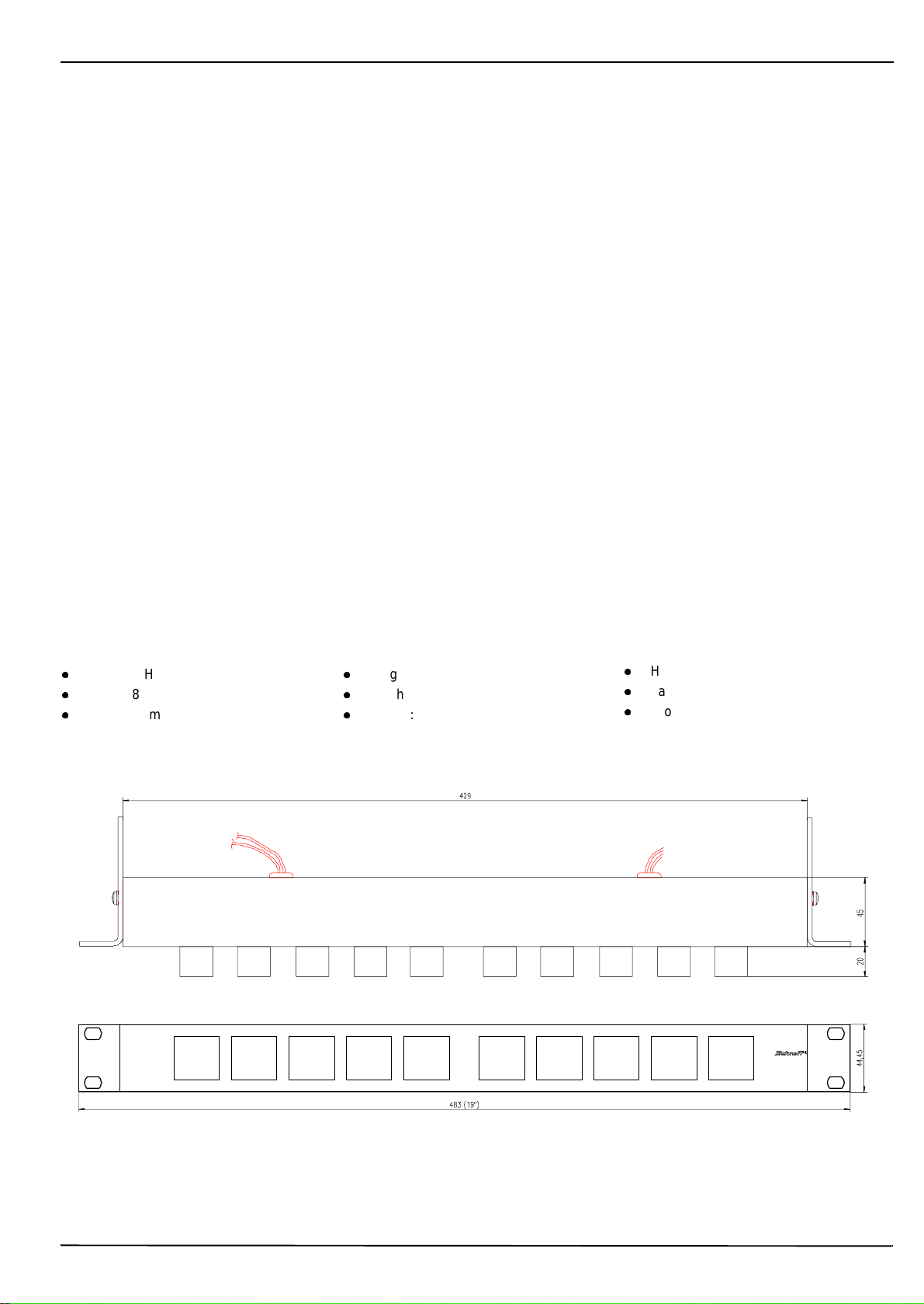
4.1 Mechanical Dimensions ............... 4
4.2 Delivery comprises ....................... 5
4.3 Operating Conditions.................... 5
4.4 Standards, Approvals.................... 5
4.5 Connectors.................................... 5
4.6 Fuses ........................................... 5
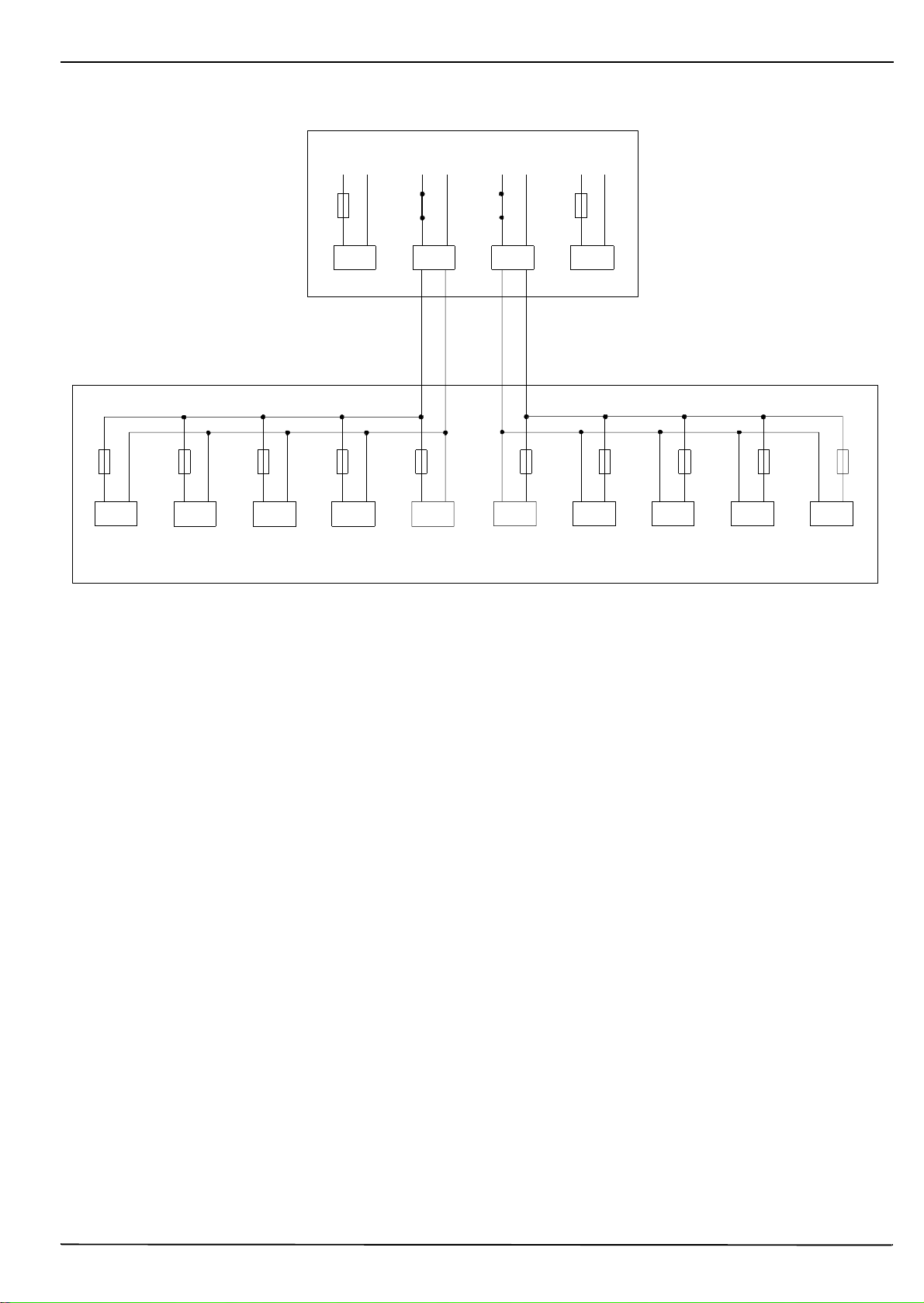
4.7 Circuit diagram ..............................6
5. Warranty conditions ....................7
2. Introduction
The distribution unit distributes power to
systems from 300 to 1000 W. The
distribution unit allows all DC-outputs and
the safety aspects of the power systems to
be transferred from the rear tothe front(e.g.
ETSI rack).
The 10 outputs at the front are in two groups
with 5 molex sockets. Each group is
supplied via a connecting cable from the
power system.
1. Inhaltsverzeichnis
1. Inhaltsverzeichnis........................ 2
2. Einleitung ................................... . 2
2.1 Sicherheitshinweise...................... 3
3. Installation.................................... 3
3.1 Mechanischer Einbau des Front-
Terminal ........................................ 3
3.2 Tauschen der Ausgangssicherung
am Power Systems gegen Kurz-
schlußbrücken ............................. 4
3.3 Verkabelung des Front-Terminal . 4
4. Technische Daten ....................... 4
4.1 Mechanische Abmessungen ....... 4
4.2 Lieferumfang ................................ 5
4.3 Betriebsbedingungen.................... 5
4.4 Normen, Approbationen ............... 5
4.5 Anschlüsse................................... 5
4.6 Sicherungen ................................ 5
4.7 Blockschaltbild .............................. 6
5. Garantiebedingungen ................. 7
2. Einleitung .
Das Frontterminal ist ein Stromverteiler für
die Power Systeme (300 oder 1000 W). Mit
dem Frontterminal werden alle DC-Aus-
gänge und die Sicherungen des Power
Systems von hinten nach vorne gelegt (z.B.
ETSI Rack).
Die 10 frontseitigen Ausgänge sind in zwei
Gruppen mit je 5 Molex Buchsen aufgeteilt.
Jede Gruppe wird über eine Anschlußlei-
tung vom Power System versorgt.
1. Table des matières
1. Table des matières ...................... 2
2. Introduction .................................. 3
2.1 Consignes de sécurité ................. 3
3. Mise en service............................. 3
3.1 Montage ....................................... 3
3.2 Shuntage du fusible de sortie du
système de puisance..................... 4
3.3 Branchement du boîtier de
distribution ................................... 4
4. Caractéristiques techniques .... 4
4.1 Caractéristiques mécaniques....... 4
4.2 Composition ............................... 5
4.3 Conditions d‘utilisation.................. 5
4.4 Normes, homologations ............... 5
4.5 Connecteurs................................. 5
4.6 Fusibles ...................................... 5
4.7 Schéma de principe...................... 6
5. Conditions de garantie .............. 7
2. Introduction
Le boîtier de distribution est prévu pour la
distribution des tensions délivrées par le
système de puissance (300 ou 1000W).
Ainsi, les sorties CC sont accessibles par
l‘avant de la baie (p. ex. bâti ETSI). Chaque
sortie est protégée par un fusible.
La face avant du boîtier de distribution
comporte 2 groupes de 5 sorties. Chaque
groupe est alimenté par un câble connecté
sur une sortie du système de puissance.

Front-Terminal
3
2.1 Safety instructions
The safety instructions must be followed
carefully to ensure that the distribution unit
is only fitted to the power system.
l
Only qualified
specialists are permitted
to install, set up, and
configure the system.
l
In order to avoid an
electric shock, always
draw the mains plug when
changing the configuration of the
system (Then, the system switches to
battery operation).
3. Setup
The system setup is to be carried out in the
following order:
3.1 Mechanical installation of the
distribution unit
3.2 Protects theoutputsafety by
eliminating possible short circuits or
bridges
3.3 Cabling of the distribution unit
3.1 Mechanical installation of
the distribution unit
The distribution unit is built into a 19” wide
enclosure and is 1 U high. It can be
mounted to the 19” profile on the cabinet
with the screws.
The distribution unit can also be recess
mounted. Here the scres must be removed
from the 19” mounting bracket,sothat itcan
be pushed into the required position. The
screws can be secured again afterwards.
Please read
the instructions
carefully
2.1 Sicherheitshinweise
Da das Frontterminal nur zusammen mit
den Power Systemen eingesetzt wird, müs-
sen die System Sicherheitshinweise beach-
tet werden.
l
Das System ist nur von
geschultem Fachpersonal
zu installieren, in Betrieb zu
nehmen und zu konfigurie-
ren.
l
Zur Vermeidung eines
elektrischen Schlages muß
bei jeglichen Änderungen an der Konfi-
guration des Systems (Verkabelung)
der Netzstecker gezogen werden (Das
System schaltet dann auf Batteriebe-
trieb).
3. Installation
Die Installation des Systems wird sinnvoller-
weise in der folgenden Reihenfolge vorge-
nommen:
3.1 Mechanischer Einbau des Front-
Terminal
3.2 Tauschen der Ausgangsicherungen
am Power Systems gegen
Kurzschlußbrücken
3.3 Verkabelung des Front-Terminal mit
dem Power System
3.1 Mechanischer Einbau des
Front-Terminal
Das Front-Terminal hat ein 19“ breites
Gehäuse und ist 1 HE hoch.Es wird mitden
beiliegenden Schrauben am 19“ Profil des
Schrankes befestigt.
Das Front-Terminal kann auch vertieft ein-
gebaut werden. Hierzu müssen die Schrau-
ben der 19“ Montagewinkel gelöst werden
und der Montagewinkel kann dann an die
gewünschte Position geschoben werden.
Danach die Schrauben wieder festschrau-
ben.
Hinweis
beachten
2.1 Consignes de sécurité
Le boîtier de distribution étant utilisé avec
un système de puissance, il est impératifde
respecter les consignes de sécurité.
l
Seul un personnel
qualifié est habilité à
installer, mettre en service
et configurer le système.
l
Afin d’éviter tout choc
électrique, toujours retirer
le cordon d’alimentation
avant tous changements de
configuration du système (le système
fonctionne alors sur batteries).
3. Mise en service
La miseen service du boîtierde distribution
doit se faire dans l’ordre suivant:
3.1 Montage
3.2 Shuntage du fusible de sortie du
système de puissance
3.3 Branchement du boîtier de
distribution
3.1 Montage
Le boîtier de distribution est au standard
19‘‘ et a une hauteur de 1 U. Il se visse sur
les montants 19‘‘ de la baie (visserie de
fixation incluse).
Le boîtier de distribution peut aussi être
monté en retrait. Il suffit alors de desserrer
les vis des équerres 19‘‘etde repositionner
celles-ci comme souhaité. Ne pas oublier
de resserrer les vis.
Respecter les
remarques

Front-Terminal
4
3.2 Shuntage du fusible de
sortie du système de
puissance
Avant de brancher le boîtier de distribution,
il faut shunter le fusible de sortie du
système de puissance concerné (shunt
fourni). Le shuntage est nécessaire pour
éviter d‘endommager les fusibles lors du
branchement du boîtier de distribution sur
les sorties du système.
3.3 Branchement du boîtier de
distribution
Deux câbles de raccordement permettent
de connecter leboîtier de distributionsurles
sorties du système de puissance. Le câble
gauche alimente les sorties 1 à 5et lecâble
droit les sorties 6 à 10.
4. Caractéristiques
techniques
4.1 Caractéristiques
mécaniques
l
Hauteur: 1 U
l
Largeur: 84 F
l
Profondeur: 65 mm
vuedeface,vuededessus
3.2 Protectstheoutputsafetyby
eliminating possible short
circuits or bridges
To ensure thesafety of the unit, the internal
FKS short circuit bridge must be replaced,
before the distribution unit is connected to
the power system. This ensures full
protection in the event of multiple switching.
3.3 Cabling of the distribution
unit
The distribution unit is connected via two
connecting cables. These are connected to
two output connectors on the power system
where the short circuit bridge is installed.
The left hand cable is for outputs 1 to 5 and
the right hand cable is for outputs 5 to 10.
4. Technical Data
4.1 Mechanical Dimensions
l
Heigth: 1U
l
Width : 84HP
l
Depth : 65 mm
Front-, plan view
3.2 Tauschen der Ausgangsi-
cherungen am Power
System gegen Kurzschluß-
brücken
Bevor das Front-Terminal angeschlossen
wird, muß bei dem Power System, an dem
dasFront-Terminalangeschlossenwird,die
Ausgangssicherung durch die beigelegten
Kurzschlußbrücke (FKS) ersetzt werden.
Dies ist notwendig, um Reihenschaltungen
von Sicherungen zu vermeiden. Dies
geschieht bei den Ausgängen des Power
Systems, auf die das Anschlußkabel des
Front-Terminal gesteckt wird.
3.3 Verkabelung des Front-Ter-
minal mit dem PowerSystem
Der Anschluß des Frontterminals erfolgt
über zweiAnschlußkabel. Diese werden an
zwei Ausgangsstecker des Power Systems
gesteckt an denen die Kurzschlußbrücke
eingebaut wurde. Das linke Kabel ist für die
Ansgänge 1 bis 5 und das rechte Kabel für
die Ausgänge 5 bis 10.
4. Technische Daten
4.1 Mechanische Abmessungen
l
Höhe : 1 HE
l
Breite: 84 TE
l
Tiefe : 65 mm
Front-, Draufsicht
Front-Terminal
123456789
10
Fuse T15A
Fuse T15A
Fuse T15A
Fuse T15A
Fuse T15A
Fuse T15A
Fuse T15A
Fuse T15A
Fuse T15A
Fuse T15A

Front-Terminal
5
4.2 Composition
1 - Boîtier de distribution
2- 2xéquerresdefixation19‘‘
3 - 10 x connecteurs
4- 10xfusiblesdesortieT15A
5- 2xcâblesderaccordement
6 - 2 x shunts
7 - Visserie de fixation
4.3 Conditions d‘utilisation
Températuredeservice:0°Cà45°C
4.4 Normes, homologations
Marquage CE
4.5 Connecteurs
Entrées:
2 x câbles AWG 10 longueur 500 mm,
équipés de connecteurs Molex
Sorties:
10xsortiesconnecteursMolex(avec
fusible)
4.6 Fusibles
15 A
Référence (10 pièces): 21191-206
Remarque:
Les fusibles se trouvent sur le -48 Vcc.
N’utiliser que des fusibles autorisés par
SCHROFF. Ne pas utiliser de fusibles de
voiture qui n’ont pas les mêmes
caractéristiques.
4.2 Delivery comprises
1 - Distribution unit
2 - 2 x 19” mounting brackets
3 - 10 x front sockets
4 - 10 x output fuses T 15 A
5 - 2 x connecting cables to power
system
6 - 2 x short circuit bridges
7- Assemblykit
4.3 Operating Conditions
Operating temperature: 0°C to 45 °C
4.4 Standards, Approvals
CE Marking
4.5 Connectors
Inputs:
DC: 2 x cable (cross-section AWG 10)
Length 500 mm over molex connector
Output:
DC: 10 x output with molex sockets (with
fuses)
4.6 Fuses
DC outputs 15 A each
Schroff Order-no. (10 pcs) 21191-206
Note:
The fuses are located in the negative rail
(-48 VDC). Only use SCHROFF fuses. Do
not use other fuses e.g. from the car
because these do not have not the requi-
red voltage range.
4.2 Lieferumfang
1 - Front Terminal
2 - 2 x 19“ Montagewinkel
3 - 10 x Frontbuchsen
4 - 10 x Ausgangssicherung T 15 A
5 - 2 x Anschlußleitungen zum Power
System
6 - 2 x Kurzschlußbrücken
7 - Montagematerial
4.3 Betriebsbedingungen
Betriebstemperatur: 0°C to 45 °C
4.4 Normen, Approbationen
CE Markierung
4.5 Anschlüsse
Eingang:
DC: 2 x Kabel (Querschnitt AWG 10,
Länge 500 mm über Molex Stecker
Ausgänge:
DC: 10 x Ausgang mit Molex Buchse (mit
Sicherung)
4.6 Sicherungen
DC Ausgang 15 A
Schroff Bestell-Nr. (10 Stück) 21191-206
Hinweis:
Die Sicherungen befinden sich im Minus-
zweig(-48V
DC). Es dürfen nur die von
SCHROFF zugelassene Sicherungen
verwendet werden; keine Standard KFZ-
Sicherungen verwenden, da diese nicht
die nötige Spannungsfestigkeit besitzen.
11301003
213 4 5 2

Front-Terminal
6
4.7 Circuit diagram4.7 Blockschaltbild 4.7 Schéma de principe
11301005
Fuse T15A
X2
Fuse T15A
X3
Fuse T15A
X4
Fuse T15A
X5
Short Circuit Bridge
X
Short Circuit Bridge
X
Fuse T15A
X
Fuse T15A
X
Fuse T15A
X1 X9X8X7X6 X10
Fuse T15A
Fuse T15A
Fuse T15A
Fuse T15A
Fuse T15A
Power System
Front - Terminal

Front-Terminal
7
5. Conditions de garantie
Garantie contractuelle
Les conditions d‘applications de la garantie,
et en particulier la durée, l‘étendue et les
cas d‘exclusion, figurent dans nos
conditions générales de ventes,
paragraphe 11 „Garantie contractuelle“.
Application de la garantie
Ce boîtier de distribution a été
soigneusement contrôlé en usine. En cas
de réclamations, veuillez nous le retourner
accompagné d‘une description la plus
précise possible du défaut constaté, et
d‘une copie du bon de livraison ou de la
facture. Le produit doit nous être retourné
dans son emballage d‘origine port assuré et
payé.
Schroffn‘assume aucune responsabilité
pour des appareils non assurés et
endommagés pendant le transport.
5. Warranty conditions
Duration
This product has a warranty of2 years. The
warranty begins on the day of delivery.
Cover of defects
Schroff will repair free of charge any faulty
functioning of the product resulting from
faulty design or defective material within the
warranty period.
All other claims under the warranty are
excluded, in particular consequential
damage.
Warranty exclusion
The warranty does not cover damage or
functional defects caused by non-
adherence to the Company´s operating
instructions or such caused by dropping,
knocking, contamination or other untoward
handling.
The warranty is invalidated if the product is
opened by unauthorized personnel,
tampered with or the serial number on the
product changed or rendered illegible.
Claims under warranty
This product has been carefully checked. If
youhaveavalidclaim,pleasereturnthe
product to SCHROFF. In order to make a
claim under the warranty, ensure that the
following is carried out:
l
Include a detailed description of the
fault.
l
The product should be returned in the
originalcarton or similar packaging,
insured andpost paid.
5. Garantiebedingungen
Leistungsdauer
Für dieses Produkt leisten wir 2 Jahre
Garantie. Der Anspruch beginnt mit dem
Tage der Auslieferung.
Umfang der Mängelbeseitigung
Innerhalb der Garantiezeit beseitigen wir
kostenlos alle Funktionsfehler am Produkt,
die auf mangelhafte Ausführung bzw. Mate-
rialfehler zurückzuführen sind. Weiterge-
hende Ansprüche – insbesondere für
Folgeschäden – sind ausgeschlossen.
Garantieausschluß
Schäden und Funktionsstörungen verur-
sacht durch Nichtbeachten unserer Bedie-
nungsanleitung sowie Fall, Stoß,
Verschmutzung oder sonstige unsach-
gemäße Behandlung fallen nicht unter die
Garantieleistung.
Die Garantieerlischt,wenn dasProduktvon
unbefugter Seite geöffnet wurde. Eingriffe
erfolgt sind oder die Seriennummer am Pro-
dukt verändert oder unkenntlich gemacht
wurde.
Abwicklung des Garantieanspruches
Das vorliegende Produkt wurde sorgfältig
geprüft und eingestellt.
Bei berechtigten Beanstandungen schicken
Sie uns das Produkt bitte zurück. Zur Erhal-
tung Ihres Garantieanspruches beachten
Sie bitte folgendes:
l
Legen Sie eine möglichst genaue
Beschreibung des Defektes bei.
l
Das Produktist im Original-Karton oder
gleichwertiger Verpackung einzusen-
den und zwar versichert und portofrei.

D/GB/F 09/01 Rev.001 1/0.5
SCHROFF GMBH 09/01
Langenalber Straße 96-100
l
D - 75334 Straubenhardt
l
Tel.: (07082) 794 - 0
l
Fax (07082) 79 4 - 200
Table of contents
Other Pentair Power Distribution Unit manuals