8
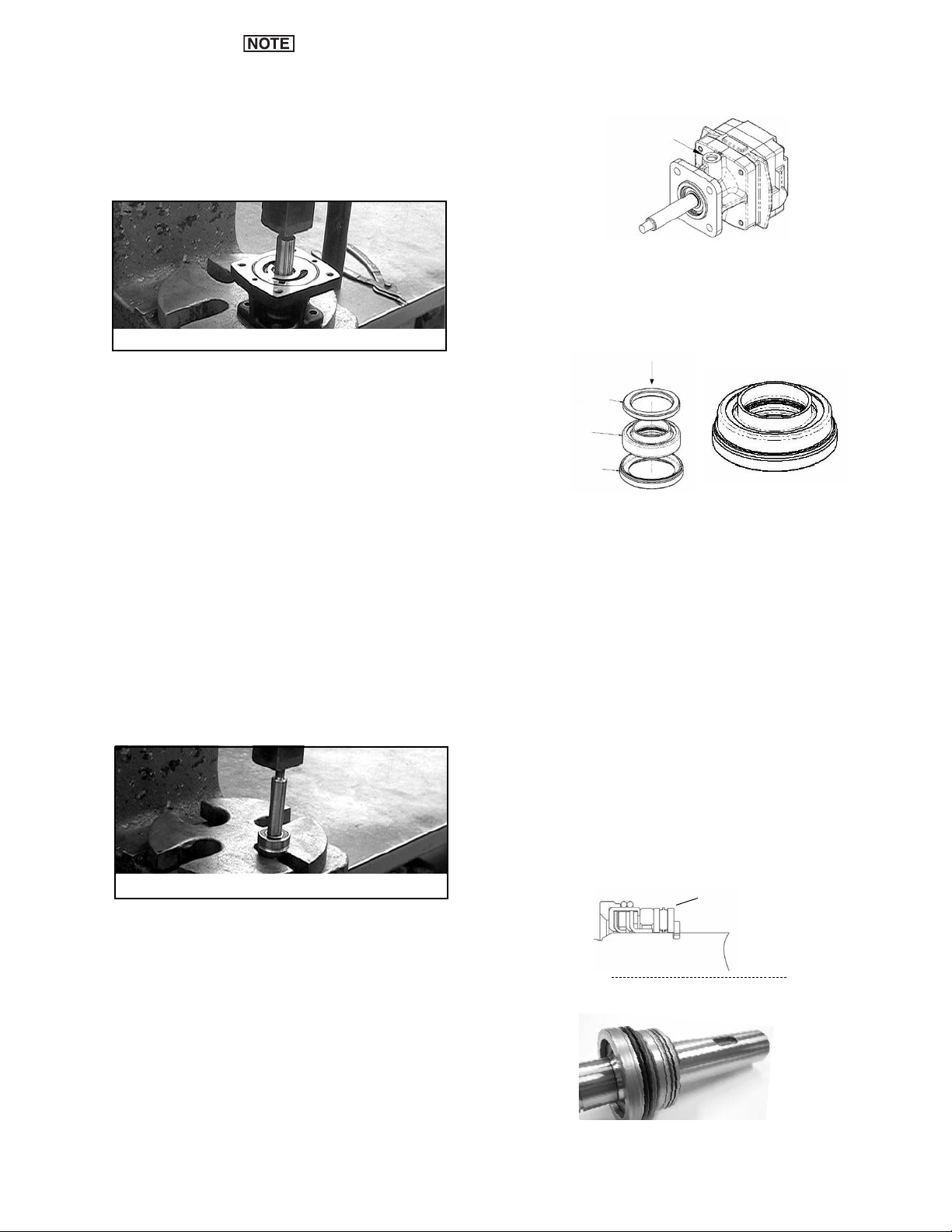
6. nstall new type seal with seal lip facing the large end of the
shaft. Slide the seal over the threaded end of the shaft and
gently push onto the raised area of the shaft. Align the seal lip
to enter the center diameter of the seal spacer and push until
seal body touches seal spacer.
Note: f the seal lip is longer than the seal spacer’s width, please
stop the assembly and review parts being used.
7. Apply a small bead of sealant on outside of the
seal body as shown (Permatex® Form-A-Gasket® No. 2
or Permatex® Gasket Sealant & Dressing No. 09974).
8. dentify new type front spacer provided in kit used only on
old type motors. Discard old front spacer from the
disassembly. (New type front spacer looks like a thick washer
with a counter bore on one side, approx .164 inch thick).
9. nstall new type front spacer by locating the counter
bore side. Face this counter bore towards the seal, and slide
spacer onto small end of shaft until the counter bore fits
onto the seal body.
10. Finished shaft sub-assembly should look like this:
11. Do not press, but place the shaft sub-assembly into the motor
body with threaded end of shaft up, taking care not to dislodge
the front spacer out of its assembled place.
Assembly Instruction for Old Seal-Type Motors
Old Seal Type
Weep hole is present only on motors manufactured with “old” type
hydraulic seal.
1. nstall the large retaining ring onto large diameter end of shaft.
2. From the small threaded end of the shaft, install the following
parts in this order: thrust bearing race, thrust bearing,
2nd thrust bearing race.
Note: The thrust bearing and races should not be reused if they are
showing any signs of wear.
3. nstall new type seal spacer provided in kit. Discard old
spacer from the disassembly. (New type seal spacer
looks like a thick washer, approx .130 inch thick).
4. Before installing the new seal, its lip must be expanded to fit on the
shaft. With the seal lip facing out, slide the seal over the threaded end
of the shaft and gently push the seal onto the raised area of the shaft.
Do not push the seal past the large retaining ring groove on the shaft.
5. Once the seal has been expanded, remove the seal from the shaft.
Weep hole
Reassembly of Remaining ydraulic Motor Parts
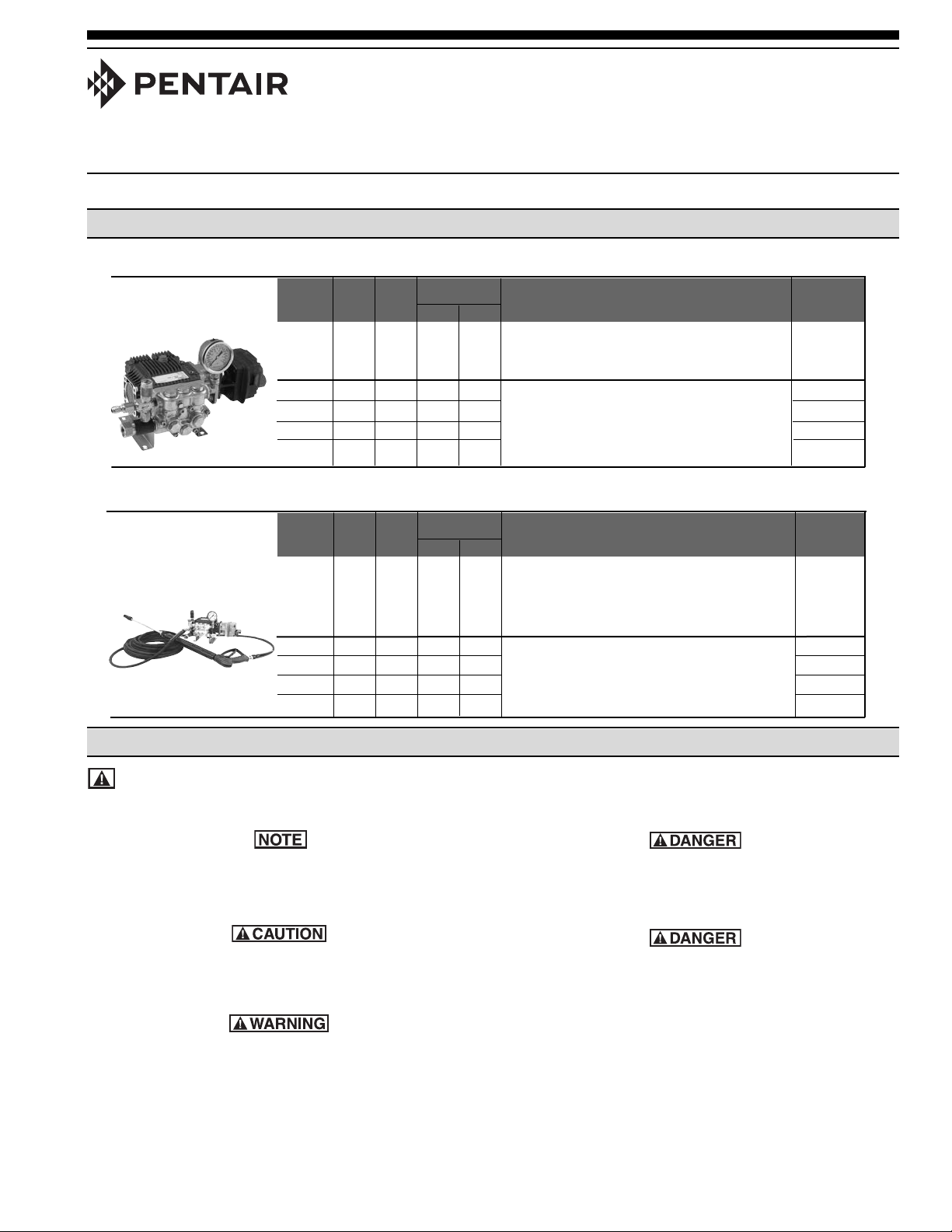
1. Place Motor Body in a vise with large end of shaft facing
up.
2. nstall the o-ring in the body.
3. nstall the Roll Pin on the shaft. Place the nner Gear of
the Gerotor onto the shaft making sure Gerotor slot
lines up with the key in the shaft.
The Roll Pin can slide up behind the inner gear of the
gerotor when the gear is installed. Make sure the key is
visible in the slot after the gear is in place.
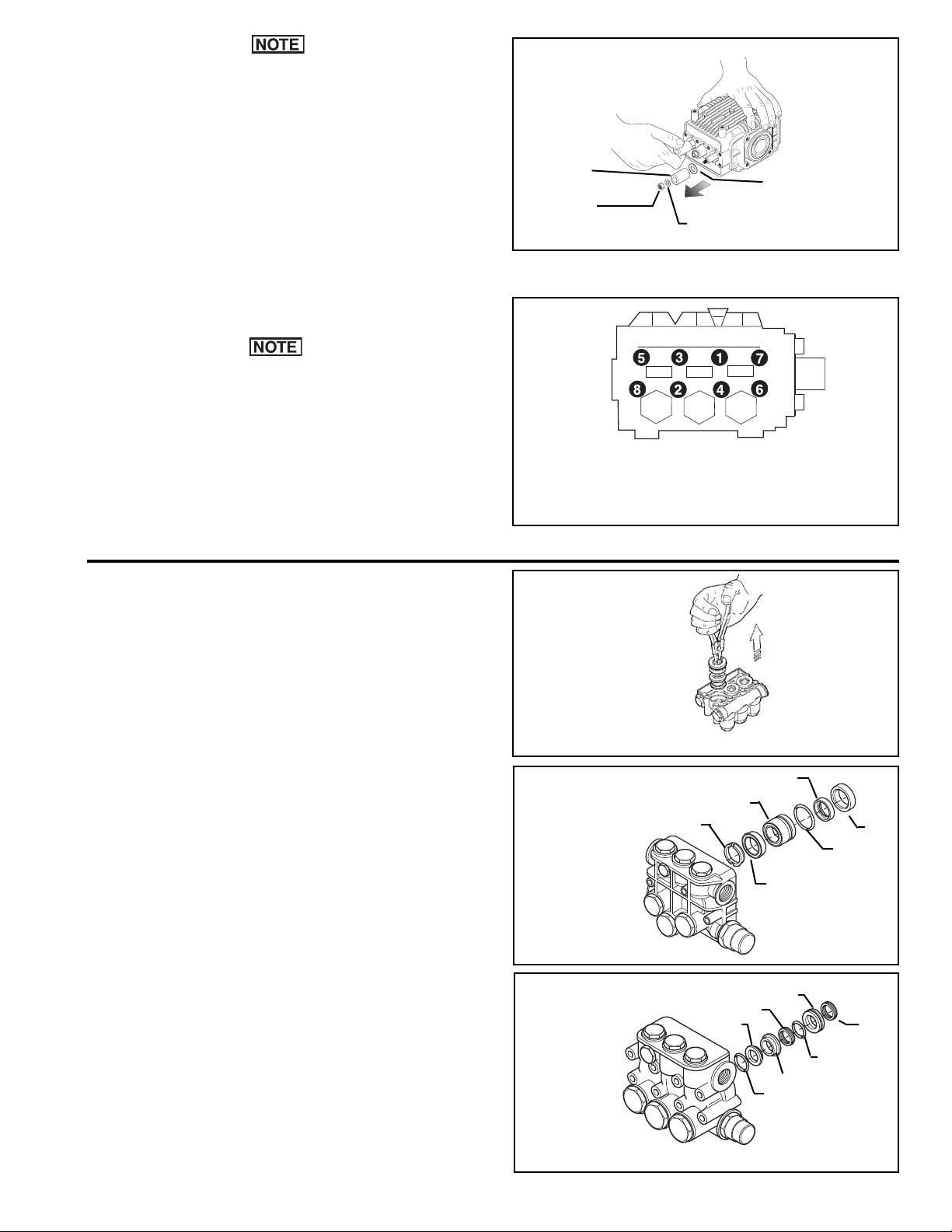
2. nstall the new ball bearing onto the small diameter
end of the shaft. Press down using the 1” x 4” pipe
until the retaining ring can be installed in its groove in
the bearing core of the motor body. nstall the retaining
ring.
3. Turn the motor body assembly over (threaded shaft
end down) on the arbor press. Press the shaft down
into its “final position” until the small retaining ring can
be installed in the shaft next to the ball bearing.
4. nstall small retaining ring on shaft.
5. Check shaft rotation at this point. t should rotate
smoothly with only slight resistance from the seal lip
pressure on the shaft. f you feel any gritty or sticking
movement, return assembly to the arbor press and
lightly press on the threaded end of the shaft to relieve
press fit compression on the thrust bearing. Note:
Don’t over do this press. The objective is to move the
small outer retaining ring installed in the
previous step back to ” touching only” the ball bearing
inner race.
Important: f gritty or sticky movement persists, it’s likely
due to re-used parts or the body needle bearing is in
need of replacement.
Figure 15
Install Shaft Sub-Assembly Into Motor Body
Important: Make sure the surface edge of the arbor press
fixture is smooth and clean. An unthreaded piece of
pipe (1” x 4” high) is needed to support the outer race
of the seal cartridge sub-assembly and outer race of
the ball bearing during assembly. Place this pipe over
the shaft threaded end for assembly of the following
steps.
1. Place the body on a support fixture in the arbor press.
Using an unthreaded piece of pipe (1” dia. x 4” high),
press the shaft subassembly down into the body until
it bottoms out. This is a light press fit and should be
done slow and easy.