Rotary pneumatic positioner F793
Installation and Maintenance Instructions
Pentair reserves the right to change the contents without notice page 2
Setting procedure
In most cases the positioner will be pre-set prior to leaving the factory. If readjustment is necessary,
follow the following instructions.
1. With the positioner correctly mounted to the actuator and cover removed, connect the air supply
and signal to the positioner.
2. Apply a of signal approximately 9 psig and gradually reduce this to 3 psig. If the actuator just
reaches the CLOSED position as the signal reduces to 3 psig, no adjustment is necessary.
3. If the actuator does not close fully at 3 psig, turn the hexagon zero adjusting nut 1/6 of a turn
clockwise and repeat step 2. Continue until zero is correctly achieved.
4. If the actuator reaches the CLOSED position before the signal reduces to 3 psig, turn the
hexagon zero adjusting nut 1/6 of a turn anti-clockwise and repeat step 2. Continue until zero is
correctly achieved.
5. Gradually increase the signal to 15 psig. If the actuator just reaches the OPEN position as the
signal reaches 15 psig, then no adjustment is necessary.
6. If the actuator does not reach the OPEN position at 15 psig, this is indicative of the spring rate
being too high. Loosen the grubscrew in the range adjustment collar, (see Fig. 3), hold the collar
stationary using a hexagon socket wrench, and turn the spring slightly clockwise. This will move
the actuator even further away from fully OPEN and the zero adjusting screw must be used to
achieve fully OPEN.
7. Conversely, if the actuator reached OPEN position before 15 psig, turn the spring slightly anti-
clockwise with respect to the rate adjusting collar. Again re-adjust the zero screw to achieve
exact fully OPEN.
The zero and range settings are highly interactive and steps 2 to 7 must be repeated until zero and
span are acceptable.
Note: In steps 3 to 7, clockwise and anti-clockwise rotations are as viewed from the adjusting nut
end of the spring.
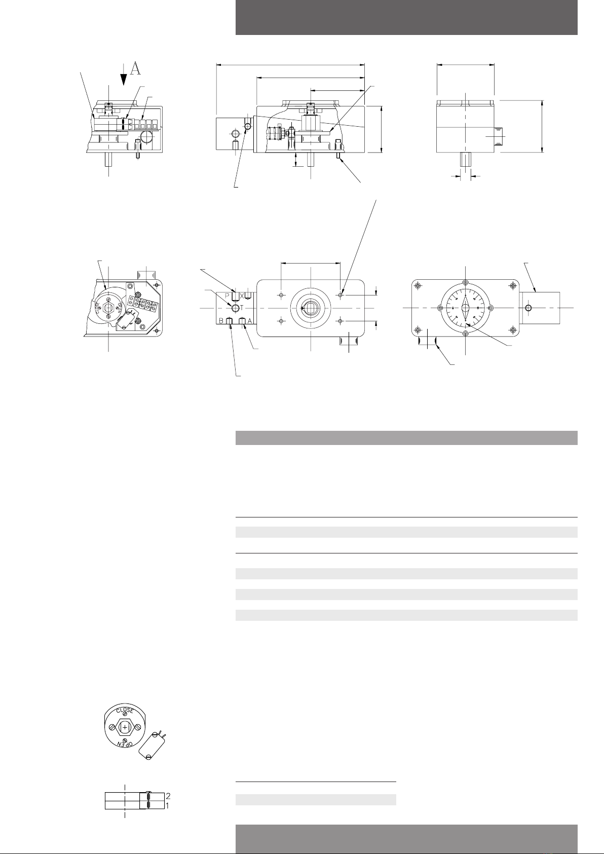
Figure 3
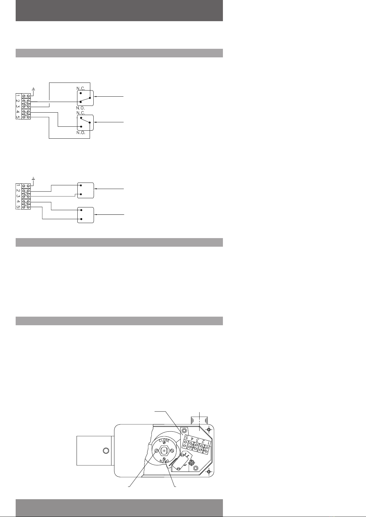
Figure 4 - Direct operation
Feedback
cam
Zero adjusting screw
Hexagonal socket
wrench
Grub screw
Hex lock nut
Range adjustment
collar
Cover fitting
Ensure that the actuator is in the position corresponding to minimum signal, ie. CLOSED for direct
operation (see Fig. 4) and OPEN for reverse operation (see Fig. 5).
1. Remove the position indicator cover and position indicator from the main cover.
2. Fit the main cover over the shaft and secure to the body using a captive screw in each corner.
3. Fit the position indicator to the double ‘D’ at the top of the shaft.
4. Fit the position indicator cover to the positioner cover so that the zero degree markings are
disposed along the transverse axis of the positioner. Before finally securing the position indicator
cover, ensure that the cover is positioned so that the arrow indicates the exact position of the
actuator.
Figure 5 - Reverse operation
Technical data
Input signal single range 3 - 15 psi (0.2 - 1.0 bar) standard.
split range 3 - 9 psi (0.2 - 0.6 bar) 9 - 15 psi (0.6 - 1.0 bar).
cam characteristics linear
3 - lobe cam: curve 1, range: 3 - 15 psi = 90° movement.
curve 2, range: 3 - 9 psi or 9 - 15 psi = 65° movement.
curve 3, range: 3 - 15 psi = 65° movement.
other characteristics on request.
Supply media compressed air or gas, dry, dust and oil free with 5 filter element to inlet.
supply pressure 30 - 100 psi (150 psi max.) 2 - 8 bar (10 bar max.).
air consumption 0.6 cfm in balanced condition with 60 psi (4 bar) supply.
Environmental environmental temperature -5° to +160°F (-20° to +70°C).
mounting and mounting position as required. No limitations.
connections mounting kit universal mounting kit for Fig.790/796 series actuators.
air connections supply and output 1/4” BSP, signal 1/8” BSP
Materials of housing anodised aluminium alloy (stainless steel optional).
construction diaphragm nitrile rubber
valve spool stainless steel
cover anodised aluminium alloy (stainless steel optional).
Weight 4 lb. (1.85kg)
Options gauges instrument air 0 - 30 psi (0 - 2 bar) - 1 off.
supply air 0 - 150 psi (0 - 8 bar) - 2 off.
integral limit switches single pole double throw 10A 240V AC
inductive proximity sensors type NT2-V3-N.
Warning!
When Pressure Gauge is not required, fit
hex head socked screw from mounting kit
using proprietary none hardening sealing
compound or tape. If there is a requirement
to remove the socket screw for future
application, an applied torque of 200 lbs/ins
should not be exceeded.