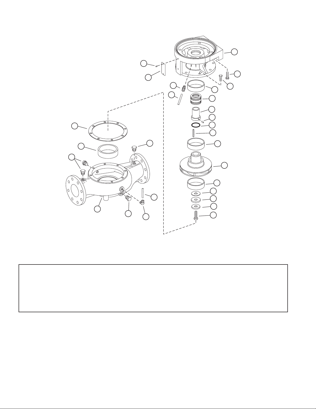
7
inspect the seal cavity in the bracket for
burrs or nicks which could damage the seat
of the seal. Apply a film of soap paste or flax
soap (do not use oil or grease) to the seal seat
and install, taking care to seat it evenly and
squarely.
NOTE: If it is not possible to insert seat with fingers,
place cardboard protecting ring furnished with seal
over lapped face of seat and press into place with a
piece of tubing having end cut square. The tubing
should be slightly larger than the diameter of the
shaft. Remove cardboard after seat is firmly in
place.
2. Position bracket (35) on the motor and secure
with capscrews (32). Tighten screws evenly to
assure properalignment.
3. If nameplate (34) was removed, install and
attach with screws (33).
4. Wipe the sealing faces of the seat and seal
washer clean. Oil these surfaces with a clean
light oil. Lightly oil the shaft sleeve (25).
Slide the entire rotating assembly onto the
sleeve. The shaft sleeve with the seal rotating
assembly on it may now be replaced on the
motor shaft. Spring tension will probably
prevent the sleeve from remaining in position
axially until the impeller is locked against it.
5. Press wearing ring(s) (7 & 16) in casing (6) and
bracket (35). Rings should not be hammered
into place. Use a press, or clamp the parts in
a bench vise, using wooden blocks to protect
the rings. It may be necessary to pin or dowel
the rings after assembly if the insert or casing
has had rings replaced before, since each
reassembly can stretch or tear metal and
thereby loosen the fits. If the facilities are
available, it is good practice to take a very
light finish cut or to ream the inside diameter
of the casing rings after pressing to restore
roundness. When rings are pressed, they may
get squeezed out of shape.
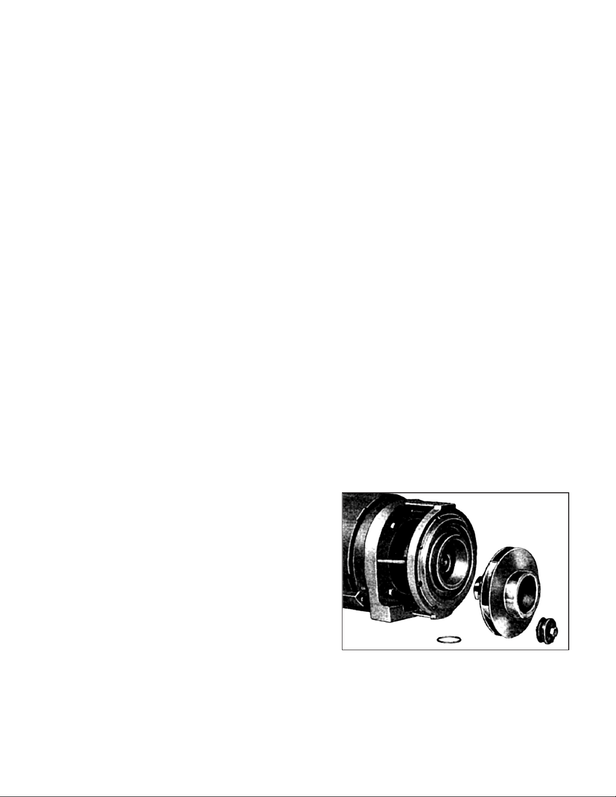
6. Place impeller wearing rings (optional – 14 and
15) on impeller (11), using the same care as for
the case wearing rings. If the rings are to be
trued on a lathe, do not clamp the impeller so
tightly that it is permanentlydistorted.
7. Carefully place gasket (10) on motor end of
impeller. Assembly key (12) and impeller (11) to
motor shaft. Secure impeller with gasket (9B),
washer (9A), and impeller screw (9).
8. Install the four pipe plugs (4) in the pump
casing. Position the gasket (8) and casing (6)
against the motor bracket and secure with
screws (5).
9. Replace all relief, cooling, flushings, or drain
lines from the pump including compression
connections (1 and 2) and tubing (3). Connect
discharge piping and suction piping if
required, making sure to install gaskets on
the flanged connections. Connect electricity
to motor.
10.Read starting instructions before attempting
to start pump.
STARTING PUMP AFTER REASSEMBLY
Do not start pump until all air and vapor has been
bled and until making sure that there is liquid in
the pump to provide the necessary lubrication.
Without the fluid around it, the seal may be ruined
in a few seconds of operation. It is possible that
the mechanical seal may drip during the first few
minutes to one hour of operation.